Abstract
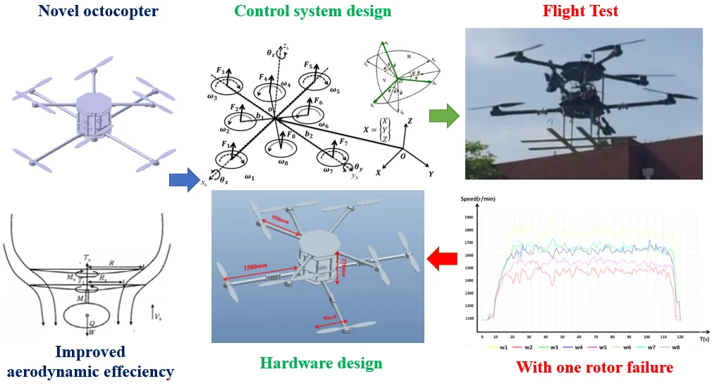
This paper describes the design and flight test of the control system of a novel octocopter with new topology to improve aerodynamic performance and efficiency. The article analyzes the advantages of the new configuration and analyzes the feasibility of the control method which can ensure fault-tolerant control when one rotor of the aircraft stops in theory. The feasibility verification is carried out through a prototype flight test. The power and hardware platform of the octocopter UAV was set up according to the requirements of structural and control system design. Flight tests were carried out multiple times, and the UAV’s redundant actuation was able to successfully stabilize the vehicle, even after a single rotor stopped functioning. Under normal flight conditions, smooth flight and effective control could be ensured for the UAV, while under the condition of a single rotor having stopped functioning, the control method was able to effectively utilize the other seven rotors to provide a proper lift force and to control the aircraft to perform basic motions such as pitch, roll, and yaw.
Highlights
- The design and flight test of the control system of a novel octocopter with new topology
- The control method can ensure fault-tolerant control when one rotor of the aircraft stops in theory
- The application of the UAV and the safe flight experiment can be expanded to more stringent conditions
1. Introduction
UAVs have been extensively studied in recent decades due to their extensive in military and civilian applications [1-6]. In most multirotor aerial vehicle configurations, rotors are located in the same plane and are symmetrically fixed on the airframe. A new type of double-layer octocopter with better aerodynamic performance was proposed in certain plane space. In the previous study of these authors, its significant improvement have been assessed and verified in aerodynamic performance [7], and its topological configuration parameters were optimized [8]. However, the purpose of engineering research is to realize the results in practice. In this research, it is hoped that the prototype can accomplish safe and controllable flight, and fly normally under special conditions where a single rotor is stopped with redundant power. Due to the new topology produced by the new configuration, the traditional PID control method needs to be redesigned and evaluated. It is necessary to conduct a theoretical analysis and experimental verification of the reliability and feasibility of its control system.
In previous studies, PID control methods have been widely used, but previous studies on PID control of multicopters are mostly focused on traditional multicopters such as quad-rotor aircraft and single-layer octo-rotor aircraft. [9-13]. Long, Liu reported the design of a novel coaxial rotorcraft UAV [14]. Mustapa Z. discussed attitude control of a quadcopter in real time application by MatLab Simulink [15]. Fu Z. Z. proposed a control system for a new structure of multicopter with its propellers installed in three different directions [16]. In Seong-Hwan, Kim’s study, an unmanned delivery service using drone was proposed, and the feasibility of its successful application was verified [17]. In most previous studies, the verification of the feasibility of the control method is limited to the simulation stage of a mathematical model. Whether the PID control method can achieve safe flight control on this new eight-rotor aircraft proposed in this paper still needs to be verified, especially in a flight experiment.
In addition, a vertical take-off and landing aircraft (VTOL), such as a helicopter, is very dangerous, as it will crash if the rotors or rotor blades do not work properly or are broken. A safe control method for an electric octocopter system was developed and validated for the multicopter, which is capable of handling heavy payload or dangerous working conditions in order to meet mission requirements. Under the condition of power redundancy, an eight-rotor aircraft can fly by adjusting the speed of the remaining seven rotors in theory. However, there is a lack of verification of experiment in the existing research, especially on such a completely novel aircraft. In this study, a new type of two-layer octocopter UAV was designed and proved that it is more reliable than a helicopter and more aerodynamic than a conventional octocopter aircraft. Through a physical experiment, it was verified that the UAV is capable of carrying out a safe flight in the face of a rotor failure by adjusting the speeds of the other seven functioning rotors. The application of the UAV and the safe flight experiment can be expanded to more stringent conditions.
The rest of this paper is organized as follows: In Section 2, the structural design of the octocopter UAV is given, and the mathematical model is proposed. The main works regarding the controller design are presented in Section 3. In Section 4, the power and hardware system of the UAV are provided. Finally, the results of the flight test and the conclusions are listed in Sections 5 and 6, respectively.
2. Octocopter model development
2.1. Structural design
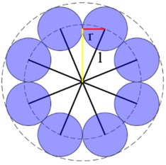
As shown in Fig. 1, the research object of this paper is a multirotor aircraft with remarkable characteristics that can realize the control of its flight attitude by adjusting the rotational speeds of its rotors. The rotor aircraft structure is more compact without the need for a tail, the thrusting force of the rotor is more balanced than that of a single-rotor aircraft, and the flight attitude is more stable. In addition, it has lower hover and take-off requirements than many other rotor aircrafts [18].
Fig. 1Novel octocopter configuration
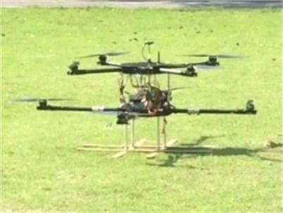
Most traditional eight-rotor aircrafts use eight rotors arranged on a single-layer fuselage structure or in pairs on four arms in a coaxial configuration. Compared to single-layer multirotor aircrafts, this work’s two-layer structure has more space by staggering the adjacent rotor, so that it can accommodate larger rotors. As shown in Fig. 2 (a)-(b), when the fuselage arm length , the maximum rotor radius of the new octocopter configuration .
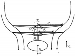
Fig. 2a) Model of flow fields in coaxial double-rotor helicopter; b) model of new octocopter configuration in upper layer; c) model of standard octocopter configuration
a)
b)
c)
According to the rotor thrust formula, assuming that the thrust coefficient and rotor angular velocity are the same, when the rotor diameter increases by more than a factor of 3, the thrust force of the multirotor aircraft can be more than 81 times than that of a single-rotor aircraft with the same fuselage size.
The thrust is , where is the density, is the rotor radius, is the rotor angular velocity, and is the thrust coefficient. Parameter is constant when the airfoil is fixed. As a preliminary work focused on the feasibility of the novel octocopter, its performance evaluation in this paper is simply based on the advantages of the maximum performance of thrust from larger rotor radius , ignoring the parameter design related to the airfoil.
Due to the lack of prior studies on the aerodynamic characteristics of coaxial multicopters, the aerodynamic characteristics of a single-rotor helicopter and a coaxial double-rotor helicopter were used to illustrate the possible thrust and aerodynamic efficiency loss of rotor aircrafts with coaxial configuration. Compared to a coaxial double-rotor aircraft, such a rotor structure effectively avoids the aerodynamic interference between the upper and lower rotors. For comparison, the following calculated upper and lower rotor thrusts were distributed, and their tensile strengths were compared to those of the rotor blades of a coaxial rotor. The setting angle of the upper rotor was 9°, and that of the lower rotor was 10°. The qualitative sketch results are shown in Fig. 2 below, which reveals that the thrusts of the upper and lower rotors were reduced compared to those of a single rotor with the same setting angle of a coaxial rotor.
For coaxial rotors, as shown in Fig. 2(c), if they are regarded as two separate rotors in the analysis, considering the influence of the flow fields of the two rotors, the trend of the induced vector gradually increases along the axial direction near the boundary in the downstream direction. For the upper rotor, due to the downward induction of the lower rotor, the practical working angle of attack decreases, so the thrust is smaller than that produced by the single upper rotor for the same collective pitch in the same working state. For the lower rotor, a large part of the airfoil cross-section is in the downwash of the upper rotor, the actual working angle of attack is much smaller, and the thrust loss is much bigger [19].
Therefore, this paper used an octocopter configuration, which was divided into two layers different from coaxial double-rotor configurations. This design both improved the efficiency of the thrust of the single rotor, and effectively avoided the aerodynamic interference between the upper and lower rotors of the coaxial double rotor. Second, octocopter aircrafts do not require a variable pitch system when flying under different conditions. The thrust forces of several rotors must be controlled to complete a flight. An octocopter aircraft is not only easier to manipulate than one with a coaxial double-rotor system, but also requires a less complicated variable pitch and transmission structure. A multirotor aircraft reduces the complexity of the structural design but complicates the installation at the same time.
2.2. Mathematical model
In this paper, a six-degrees-of-freedom simulation model of an octocopter aircraft was established, and Newton-Euler’s six-degrees-of-freedom inertia equation was adopted. The body posture and flight position were described using two coordinate systems: A geodetic coordinate system and a body coordinate system [20]. The Euler-Lagrange and Newton–Euler formulations are the two broadly adopted approaches for the dynamic analysis of robot manipulators [21].
The related coordinate system was firstly defined to establish a mathematical model of the system.
Fig. 3Mathematical system description. O-XYZ– global coordinate frame; o-xyz – moving coordinate frame; θx, θy, and θz– attitude angles; ωi (i= 1~8) – angular rotor velocity; Fi (i= 1~8) – rotor thrust
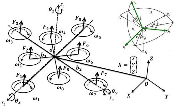
As shown in Fig. 3, - is the ground inertial coordinate system, which is a fixed coordinate system with respect to the ground; - is the body axis coordinate system – the origin is fixed at the fuselage’s center of gravity, and the axes and are fixed in the fuselage. is the angle between and the plane -, which represents the pitch angle; is the angle between the projection of the axis of the body axis coordinate system in the horizontal plane and the axis of the ground coordinate system , which represents the yaw angle; is the angle between the axis of the body axis coordinate system and the vertical plane through the body's axis , which represents the roll angle.
Without considering the linear motion between the two coordinate systems, that is, if it is assumed that and coincide with one another, it is possible to rotate the two coordinate systems so that they overlap. Therefore, it is possible to obtain the coordinate transformation matrix of the two coordinate systems:
where represents , represents , and the other signs have similar meanings. , , and represent the angles of the yaw, pitch, and roll, respectively. The thrust force of the eight rotors is ( 1, 2, 3, 4, 5, 6, 7, 8) in the body axis coordinate system, and the thrust of the aircraft can be expressed as:
The thrust in the ground inertial coordinate system is obtained using the coordinate transformation matrix , that is:
Ignoring the air resistance of the aircraft, it is possible to obtain as follows:
where is the mass of the octocopter aircraft and represents the gravitational acceleration. As shown in Fig. 3, the forward direction is defined as the positive direction of the -axis in the body axis coordinate system. When the receiver receives a left turn signal, the flight control program increases the speed of rotors 2, 3, and 4 and reduces the speed of rotors 6, 7, and 8, which can increase thrusts , , and and can reduce thrusts , , and . A rolling moment toward the left of the mass center of the aircraft is then exerted on the blades, making the aircraft perform a rolling to perform the left maneuver. In contrast, when the receiver receives a right turn signal, the flight control program reduces the speed of rotors 2, 3, and 4 and increases the speed of rotors 6, 7, and 8, which can reduce thrusts , , and and can increase thrusts , , and . A rolling moment toward the right of the mass center of the aircraft is then exerted on the blades, making the aircraft perform rolling to perform the right maneuver. Therefore, the rolling movement can be carried out by controlling the difference in speed between rotors 2, 3, and 4 and rotors 6, 7, and 8.
The principles of the pitching and rolling movements of the multirotor aircraft are similar. When the receiver receives the order of flying forward, the flight control program increases the speed of rotors 4, 5, and 6 and reduces the speed of rotors 1, 2, and 8, which can increase thrusts , , and and reduces thrusts , , and . A forward pitching moment toward the mass center of the aircraft is then exerted on the blades, making the aircraft perform a flying forward maneuver. In contrast, when the receiver receives the order of pitching backward, the flight control program reduces the speed of rotors 4, 5, and 6 and increases the speed of rotors 1, 2, and 8, which can reduce thrusts , , and and increases thrusts , , and . A backward pitching moment toward the mass center of the aircraft is then exerted on the blades, making the aircraft perform a flying backward maneuver. Therefore, a pitching movement can be carried out by controlling the difference in speed between rotors 1, 2, and 8 and rotors 4, 5, and 6.
The yawing movement of the multirotor aircraft is mainly realized by the difference in torque between the positive and negative rotors. In the design of a multirotor system, in a view looking down, a rotor with a counterclockwise rotation is generally defined as a positive rotor, while a rotor with a clockwise rotation is defined as a negative rotor. Applying this condition to the aircraft designed in this paper, rotors 2, 4, 6, and 8 are positive rotors, and rotors 1, 3, 5, and 7 are negative rotors. The aircraft can fly in the positive direction by increasing the speeds of rotors 1, 3, 5, and 7 and by reducing the speeds of rotors 2, 4, 6, and 8, while it can fly in the negative direction by reducing the speeds of rotors 1, 3, 5, and 7 and by increasing the speeds of rotors 2, 4, 6, and 8. Therefore, a yawing movement can be carried out by controlling the difference in speed between rotors 1, 3, 5, and 7 and rotors 2, 4, 6, and 8.
, and define the moments of inertia regarding the three axes of the octocopter aircraft, and , and are actual torques generated by eight rotors, which refer to the rolling, pitching, and yawing movements. Assuming that the structure of the octocopter aircraft is completely symmetrical and ignoring air resistance and gyroscopic effects, the equations of small-angle motion for this system are as follows:
where , are constants; and refer to the length of the upper and lower fuselage arms, respectively; , represents the angular velocity of the eight rotors.
The total thrust is:
where is a constant. Finally, it is possible to obtain a simplified mathematical model of the octocopter aircraft as follows:
The verification of model in Eq. (7) can rely on the flight experiment shown in Section 5, which can verify the model of octocopter UAV accurately, rather than relying on computer simulation only.
3. Control system design
The control of the octocopter aircraft was achieved by adjusting the speeds of the eight rotors, and was realized through two control loops: The inner loop used to control the attitude of the aircraft, and the outer loop used to control the position of the vehicle. The specific control methods are introduced below.
3.1. Attitude calculation module
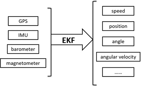
The attitude calculation module obtains data from sensor modules, including GPS (Global Positioning System), IMU (Inertial Measurement Unit), barometer, and magnetometer, using the Uorb method. Then, the data, including the speed, position, angle, and angular velocity, can be calculated using the extended Kalman filtering (EKF) algorithm. This module never stops throughout the flight and always provides real-time data for other modules. Fig. 4 presents the attitude algorithm schematic.
Fig. 4Attitude algorithm schematic
3.2. Attitude and position control modules
Position and attitude control are two of the most important modules of a multirotor aircraft. The normal operation of these two modules is related to the flight safety of the aircraft. Attitude control has a high operation speed, which can significantly affect the flight safety, so the attitude control module was designed as the inner loop. The operating speed of the position control is low, which causes a relatively smaller impact on the flight safety, because the position control module was designed as the outer loop. The feedback data of these two modules come from the attitude calculation module, which is also regulated by the flight mode and its related parameters. The PID controller is proposed for attitude and position control, which parameters are pre-set based on the UAV model, and will not be tuned adaptively. The PID controller generates tracking control based on error feedback, and makes the position and attitude of UAV track the desired state in real time.
3.2.1. Attitude control
The attitude control also consists of two parts. The outer loop is controlled by the proportional control of the angle, and the inner loop is controlled by the PID control of the angular velocity. Because the ultimate objective of controlling the rotor’s rotation is the angular velocity, a more complete inner-ring PID control scheme was designed for the angular velocity.
For a given attitude angle , the feedback attitude angle is:
where , , are control parameters of the PID controller, , and are the rotational errors, and , , and are the outputs of the attitude control.
Then, the model of rotation can be obtained as:
where, the designed control torque is:
Thus, the control torques , and are the theoretical PID-designed controllers for actual torques , and .
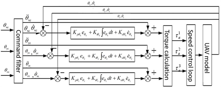
Then, it is possible to obtain the attitude control loop. A block diagram of the control scheme is shown in Fig. 5. The attitude and speed of rotation can be obtained by integrating the UAV model mentioned in Eq. (9).
Fig. 5Attitude control loop. UAV, unmanned aerial vehicle
3.2.2. Position control
The aforementioned incremental digital PID control principle is important for achieving precise position control. When the sampling time is very small, the algorithm is accurate, and it is simpler and more flexible than the traditional analog PID control method.
The position controller consists of two parts: The inner loop is the PID speed control, while the outer loop is the displacement control. The main purpose of this structure is to facilitate the control of different flight modes and to enable modular design.
Since speed control is an indispensable part for most of models, with a more complete inner-loop PID control of the speed, the speed can be controlled in specific modes to control the corresponding displacements, as a proportional controller can meet the control requirements.
Similar to the attitude control system design, is a desired translational state, and is the translational state for feedback:
where , , are control parameters of the PID controller; , and are the translational errors; , and are the velocity errors; , and are the velocity states for feedback; , , and are the outputs of the controller:
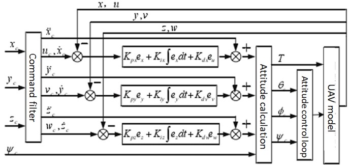
Then, it is possible to obtain the position control, as shown in Fig. 6.
Fig. 6Position control loop, where ϕc, θc, and ψc are the specified attitude angles, and T is the control torque
3.3. Safe flight control system: under actuation
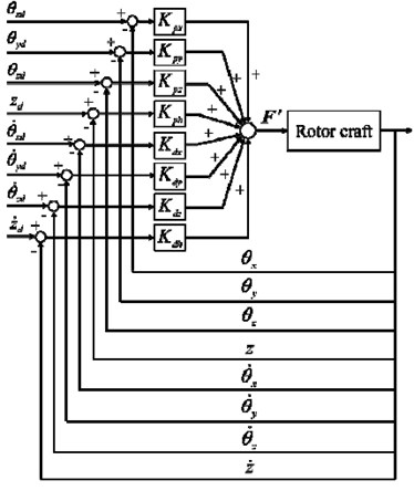
In this paper, it is proved that an octocopter aircraft can continue to fly safely even when one rotor stops functioning. Fig. 7 shows a block diagram of a safe flight control system. Safe flight control is performed by using the attitude angles and angular velocities of the aircraft. The altitude and velocity in the -direction of the craft are also controlled so that the aircraft does not fall down. Feedback control is used to achieve control using the difference between the expected value and the current value. In this paper, when one of the eight rotors stopped functioning, the other seven rotors were controlled to fly. For example, when rotor 1 stops, the seven rotors of thrust ( 2, 3, 4, 5, 6, 7) have the following parameters:
where , , and are the proportional gains for the attitude angles , and , respectively; is the proportional gain of the aircraft altitude in the -direction; , , and indicate the differential gains for the angular velocities around the , , and axes; is the differential gain for the velocity in the altitude direction of the aircraft.
In case a rotor stops, the work of the other seven rotors can still complete the attitude control of the pitch, roll, and yaw angles to ensure the safe flight of the aircraft. The aircraft can still be rapidly adjusted to the predetermined flight height and horizontal position and the control system can maintain a fixed-point hover in a stable condition.
Fig. 7Block diagram of safe flight control system
3.4. Stability analysis of the controller
A PID-based controller is proposed for the novel UAV control in this paper, which is one of the earliest control strategies developed. Due to its simple algorithm, good robustness, and high reliability, it is widely used in UAVs’ position and attitude control. As shown in Figs. 5 6, PID is divided into three links, namely proportional (, ), integral (, ), and derivative link (, ). The functions of each link are as follows:
(1) Proportional link: This link reflects the deviation signal of the UAV position and attitude control system. Once the deviation occurs, the controller immediately takes control to reduce the deviation.
(2) Integral link: This link is used to eliminate the steady-state error after entering the steady-state
(3) Differential link: This link reflects the changing trend of the deviation signal. By introducing an effective early correction signal to the system, the speed of the system is accelerated, and the adjustment time is reduced.
In summary, PID starts from the above three links to achieve the stability of the UAV's position and attitude.
4. Power and hardware design for UAVs
4.1. Power system design
The designed unloaded weight of the octocopter aircraft was 8.85 kg with a fully loaded weight of 20 kg, and the following power system was designed. Considering the service life and flight safety of the motor and that a conventional multirotor aircraft usually takes off at approximately 50 % of the throttle, when the fully loaded weight of the octocopter aircraft was 20 kg, the thrust of the single rotor was approximately 2.5 kg, the hurricane U4114 motor was used, and the KV value was 320. The related parameters of the motor are shown in Table 1. It can be seen that when the U4114 motor was equipped with an 18-inch rotor, the current of the 50 % throttle was 14 A, the thrust was 2375 g, and the eight motors were able to meet the thrust requirement.
Table 1U4114 motor parameters.
Model | Voltage (V) | Rotor | Accelerator | Electric current (A) | Thrust (g) | Power (W) | Efficiency (g/W) | Operating temperature (°C) |
U4114 KV320 | 24 | JF 15×55 | 2 | 560 | 44 | 12.73 | ||
4 | 950 | 88 | 10.8 | |||||
6 | 1310 | 132 | 9.92 | |||||
8 | 1565 | 176 | 8.89 | |||||
10 | 1775 | 220 | 8.07 | |||||
12 | 2045 | 264 | 7.75 | |||||
14 | 2315 | 308 | 7.52 | |||||
100 % | 16.9 | 2610 | 371.8 | 7.02 | 49° | |||
JF 18×65 | 2 | 600 | 44 | 13.64 | ||||
4 | 1055 | 88 | 11.99 | |||||
6 | 1380 | 132 | 10.45 | |||||
8 | 1730 | 176 | 9.83 | |||||
10 | 1950 | 220 | 8.86 | |||||
12 | 2170 | 264 | 8.22 | |||||
14 | 2375 | 308 | 7.71 | |||||
16 | 2545 | 352 | 7.23 | |||||
18 | 2715 | 396 | 6.86 | |||||
20 | 2860 | 440 | 6.5 | |||||
22 | 3045 | 484 | 6.29 | |||||
24 | 3150 | 528 | 5.97 | |||||
100 % | 27.5 | 3570 | 605 | 5.9 | 73° |
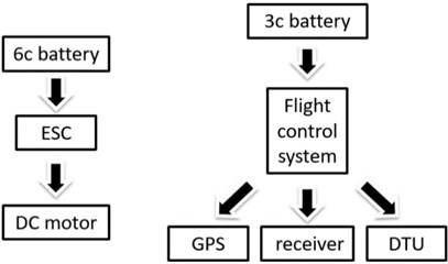
It can be seen from the selection of the motor and rotor that the maximum current of the octocopter system was over 100 A, and the maximum power was over 3000 W. Both the current and power were relatively large. Therefore, the power supply of the power system was independent from the power supply of the control system. The power supply system was divided into two parts: A high-power supply system, where a 6c battery of 16,000 mAh was used to power the eight brushless ESCs (Electronic Speed Control) and the eight motors, and a low-power supply system with 3300 mAh 3c batteries to power the flight controller, which is more compact in design but also avoids the interference of the two parts. The power supply system is shown in Fig. 8.
Fig. 8Electrical power generation system
4.2. Hardware design
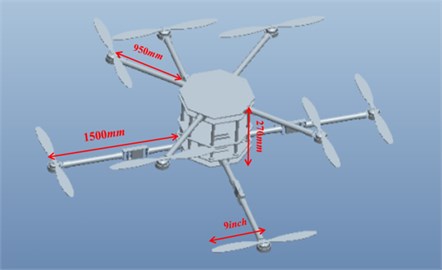
As shown in Fig. 9, the length of upper fuselage arm was 950 mm and the length of lower fuselage arm was 1500 mm. The vertical distance between the rotor planes was 270 mm. The two layers were fixed and connected by eight long aluminum rods, and a partition was designed between the two layers to hold the necessary hardware of the control system. The partition was secured to the lower layer by a battery rack placed below it. The electrical control and its related wiring were set in the seam, and the fuselage was made of carbon fiber with a thickness of 3 mm.
Fig. 9Structural dimension of octocopter fuselage parameters
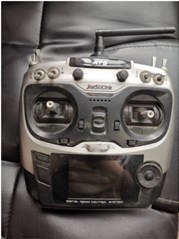
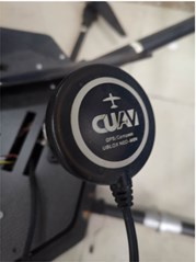
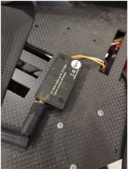
The flight control system consisted of two microprocessors. The main controller was based on STM32F427, and the co-controller was based on STM32F100, in order to be able to switch to the co-processor to continue the flight when the master control failed. The GPS in Fig. 10(b) received data from multiple satellites, which was integrated to estimate the position and other relevant information. The GPS was inserted into the flight control system through the flight control external interface, and data interaction with the flight control system was conducted. Fig. 10(c) shows a wireless digital transmitter; its function is data communication with the ground station. It is convenient for the flight control system to tune the parameters and to monitor changes in the flight data in the process of a real-time flight, thus maintaining a safe flight. A wireless digital transmitter, which could cover the range of 1000-1500 m in an ideal environment, was able to meet the requirements of the mission. The transmitter consisted of two identical parts, one plugged into the flight control system’s external interface and another connected to the ground station. The main function of the remote control shown in Fig. 10(a) was the real-time operation of the flight process and the switching of the flight mode. The remote-control receiver was attached to the flight controller.
Fig. 10Hardware system: a) remote control; b) M8N GPS; c) wireless data transmission
a)
b)
c)
5. Flight test and analysis
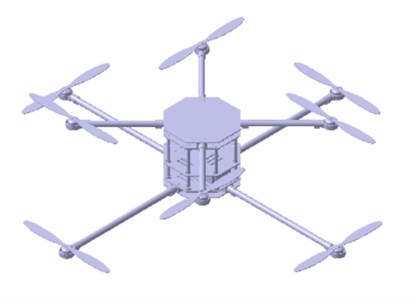
Fig. 11 shows the multirotor aircraft during the flight test. The flight test was undertaken under the conditions of clear weather, a wind speed of 13 km/h, air humidity of 47 %, and a temperature of 30 °C. Fig. 12 shows the speed and position changes of the UAV along the , , and axes. After the first flight test without taking off, another flight test was conducted with a larger angle and speed. As shown in Fig. 12, which indicates that the aircraft rolled, pitched, and deflected over different degrees of freedom, the flight safety control system of the aircraft was reliable and effective.
Fig. 11Flight test
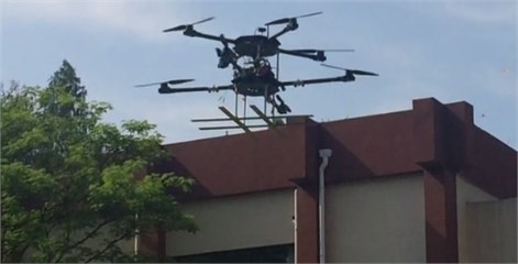
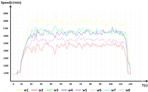
Fig. 12 shows the rotor speed output of the octocopter aircraft. In normal flight mode, the upper forward rotors 2, 4, 6, and 8 have lower reversals than rotors 1, 3, 5, and 7 to overcome the torque. The speeds of the upper four rotors, namely, 2, 4, 6, and 8, were faster than the speeds of the lower four rotors, namely, 1, 3, 5, and 7, because the upper machine arm is shorter than the lower machine arm. Due to the attitude control of the deflection angle, the rotation speeds of rotors 1, 3, 5, and 7 and those of rotors 2, 4, 6 and 8 were negatively correlated with the adjustment of the flight control system.
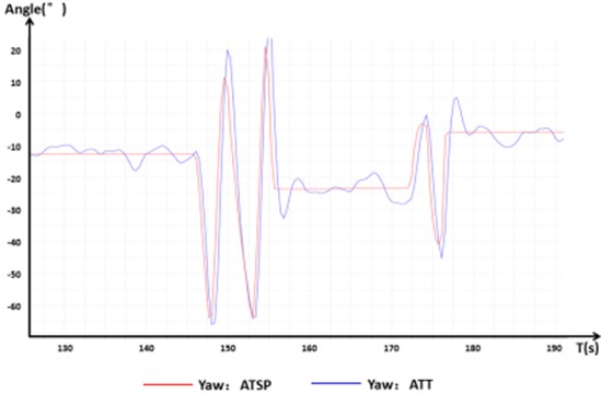
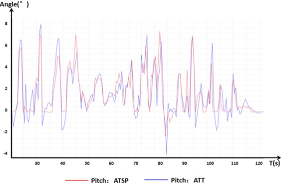
In the following figures, the ATSP is the input control signal, and the ATT is the actual measured flight data. Fig. 13 shows that the control signals of the pitching, tumbling, and yawing movements of the aircraft during a normal flight were normal and rapid. The aircraft showed good handling in various flight actions. In these experiments, more than 10 deg reached is completely feasible and well controlled by the designed controller. As long as the vertical component of the thrust produced by the rotor is greater than the gravity of the octocopter, the vehicle is controllable. This also illustrates the benefits of increasing maximum thrust for UAV performance.
Fig. 12Flight motor speed chart in normal flight
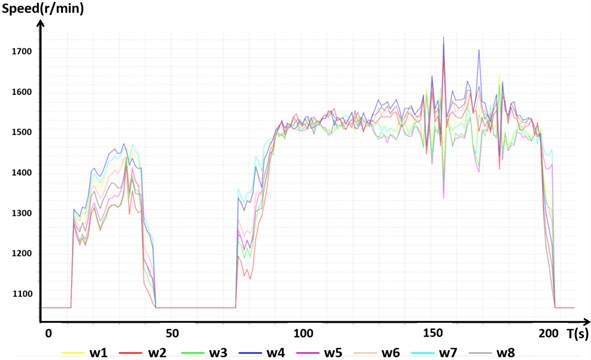
Fig. 13Control signal response in normal flight
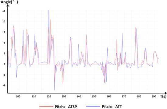
a) Pitch angle
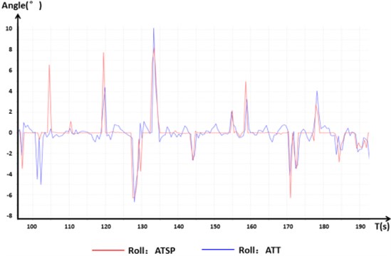
b) Roll angle
c) Deviation angle
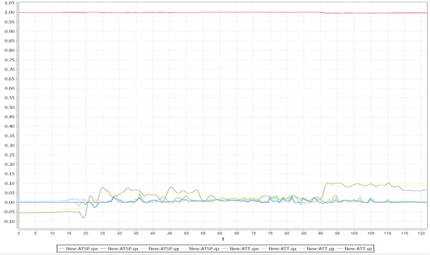
Fig. 14 shows the quaternion input and response in the normal flight test. Quaternions are dimensionless hypercomplex numbers. To avoid a singular solution and to reduce the calculation of trigonometric functions in the simulation of an aircraft motion test, the quaternion is used to replace the Euler angle in the motion equation of the aircraft. The quaternion method can avoid the appearance of a singularity and can guarantee that the calculation and simulation test do not break under any flight conditions. This method also reduces the trigonometric function evaluation, thus saving the calculation time. Although the physical meaning of quaternions is not as clear as that of the Euler angle, it can still be observed in the figure that the numerical change was stable and the output response was fast.
Fig. 14Quaternion input and response
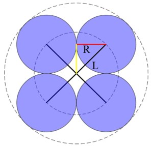
As for experiments when one rotor fails, one rotor was set to stop functioning while other seven rotors still rotated at the beginning of the flight test. Figs. 15-17 illustrates the fault tolerant capabilities. Fig. 15 shows the rotor speed output of the octocopter aircraft when one rotor stopped functioning. We found that the flight was safe and controllable and was reliable and effective in each attitude through the flight test. After motor 1 stopped functioning, the output signal increased. The safe flight control system automatically adjusted the speed of the other seven motors because motor 1 did not respond. To balance the counter-torque and to maintain the thrust force at the same time, the rotating speed of the upper motors 2, 4, 6, and 8 became relatively lower, while the speed of the lower motors 3, 5, and 7 increased. To balance the pitch attitude, the motor speed of rotor 5, which was on the opposite side of rotor 1, increased less. At the same time, the speed of rotors 2 and 8 in the lower layer was higher than that of rotors 4 and 6 to overcome the pitching moment caused by the stopping of rotor 1.
Fig. 15Flight motor speed chart with one rotor stopped
It can be seen from Fig. 16 that the cease in function of a single rotor has a certain influence on the pitch, roll, and yaw motions of the aircraft compared to those of normal flight. The rotation of the single-rotor that stopped functioning had the greatest influence on the change in the deflection angle. The control response of the deflection angle was slower, and the error was larger in order to maintain the flight attitude of the aircraft and the flight movements in the other degrees of freedom.
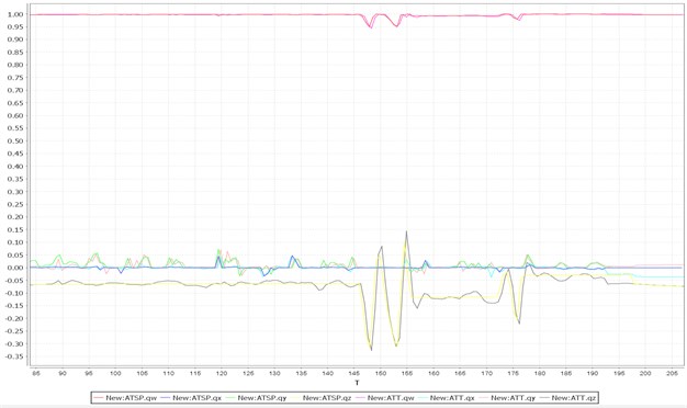
Fig. 17 shows the quaternion input and response in the flight test after one rotor stopped functioning. Under the condition of a single rotor having stopped functioning, compared to normal flight, the output error of the corresponding change was larger, especially in the value . This can be seen as a sacrifice by the aircraft flight control system to ensure the safety and stability of the flight.
Fig. 16Control signal response with one rotor stopped.
a) Pitch angle
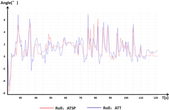
b) Roll angle
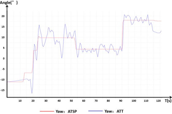
c) Deviation angle
Fig. 17Quaternion input and response with one rotor stopped
6. Conclusions
This paper aimed to design a novel model of a double-deck octocopter UAV with high efficiency and reliability using a PID-based control algorithm for safe and reliable flight requirements. Meanwhile, the effect of one rotor stop was also analyzed. Under normal flight conditions, this new two-layer octocopter UAV can effectively ensure smooth flight and control. Under the condition of one rotor stop, the control method can effectively utilize the other seven rotors to provide a proper thrust force and to control the aircraft to perform basic motions such as pitch, roll, and yaw. The automatic control under this control algorithm appears robust and intelligent, considering the control effects. The control characteristics of the octocopter are more stable compared to the traditional four-rotor UAV, more control variables make the control system have more options to realize accurate control. The modified octocopter also has better reliability and fault tolerance, and the effect of single rotor stopped was verified through experiment in this study which is hardly achieved by traditional four-rotor aircraft. The octocopter has better ability to adapt to the harsh operating environment such as the battlefield. In the case of thrust redundancy, the eight rotor UAV can realize safe flight with up to four rotors stopped theoretically. The new design allows the arrangement of larger rotors and reduces the loss of aerodynamic efficiency through the staggered rotors configuration as well.
The current study is focused on the feasibility verification of a novel octocopter by flight tests. Regarding any future works, the development of more accurate aerodynamic analysis methods can aid in a more detailed thrust analysis and, in turn, a more targeted octocopter performance investigation. Moreover, when it comes to the detailed design of the novel octocopter, some of the important parameters are missing for a definite configuration to be drawn. For example, more detailed research is required for making the propulsion system sizing methodology considering power consumption, and optimal design considering parameters affecting performance of this configuration before an essential evaluation for UAVs applications can be conducted. Most importantly though, it should be noted that to go beyond the suggestions of the current study and to reach a solid conclusion concerning the technologies selection, other aspects such as costs and compatibility with other technologies shall also be considered. As for control issue, the fault diagnosis and over-saturation problem for UAV fault-tolerant control can be considered. This will in turn require a more detailed and quantitative analysis based on the current work serving as the first step.
References
-
Y. Zou and Z. Meng, “Coordinated trajectory tracking of multiple vertical take-off and landing UAVs,” Automatica, Vol. 99, pp. 33–40, Jan. 2019, https://doi.org/10.1016/j.automatica.2018.10.011
-
S. Bayraktar and E. Feron, “Experiments with small unmanned helicopter nose-up landings,” Journal of Guidance, Control, and Dynamics, Vol. 32, No. 1, pp. 332–337, Jan. 2009, https://doi.org/10.2514/1.36470
-
A. Abdessameud and A. Tayebi, “Global trajectory tracking control of VTOL-UAVs without linear velocity measurements,” Automatica, Vol. 46, No. 6, pp. 1053–1059, Jun. 2010, https://doi.org/10.1016/j.automatica.2010.03.010
-
Luis Rodolfo García Carrillo, Gerardo Ramon Flores Colunga, Guillaume Sanahuja, and Rogelio Lozano, “Quad rotorcraft switching control: An application for the task of path following,” IEEE Transactions on Control Systems Technology, Vol. 22, No. 4, pp. 1255–1267, Jul. 2014, https://doi.org/10.1109/tcst.2013.2284790
-
Y. Zhang and J. Jiang, “Bibliographical review on reconfigurable fault-tolerant control systems,” Annual Reviews in Control, Vol. 32, No. 2, pp. 229–252, Dec. 2008, https://doi.org/10.1016/j.arcontrol.2008.03.008
-
A. Bani Milhim, “Modeling and fault tolerant PID control of a quad-rotor UAV,” Concordia University, 2010.
-
H. Zhu, H. Nie, L. Zhang, X. Wei, and M. Zhang, “Design and assessment of octocopter drones with improved aerodynamic efficiency and performance,” Aerospace Science and Technology, Vol. 106, p. 106206, Nov. 2020, https://doi.org/10.1016/j.ast.2020.106206
-
H. Zhu, H. Nie, L. Zhang, S. Deng, and X. Wei, “Aerodynamic design optimization of a staggered rotors octocopter based on surrogate model,” Journal of Aerospace Engineering, Vol. 34, No. 4, p. 14, Jul. 2021, https://doi.org/10.1061/(asce)as.1943-5525.0001280
-
Y. Yang and Y. Yan, “Attitude regulation for unmanned quadrotors using adaptive fuzzy gain-scheduling sliding mode control,” Aerospace Science and Technology, Vol. 54, pp. 208–217, Jul. 2016, https://doi.org/10.1016/j.ast.2016.04.005
-
A. Mahmood and Y. Kim, “Leader-following formation control of quadcopters with heading synchronization,” Aerospace Science and Technology, Vol. 47, pp. 68–74, Dec. 2015, https://doi.org/10.1016/j.ast.2015.09.009
-
A. B. Junaid, Y. Lee, and Y. Kim, “Design and implementation of autonomous wireless charging station for rotary-wing UAVs,” Aerospace Science and Technology, Vol. 54, pp. 253–266, Jul. 2016, https://doi.org/10.1016/j.ast.2016.04.023
-
T.-H. Huang, J.-Y. Kuan, and H.-P. Huang, “Design of a flexible high performance quadcopter platform breaking the MAV endurance record with laser power beaming,” in 2011 IEEE/RSJ International Conference on Intelligent Robots and Systems (IROS 2011), pp. 5166–5172, Sep. 2011, https://doi.org/10.1109/iros.2011.6048336
-
S. Kiribayashi, J. Ashizawa, and K. Nagatani, “Modeling and design of tether powered multicopter,” in 2015 IEEE International Symposium on Safety, Security, and Rescue Robotics (SSRR), pp. 1–7, Oct. 2015, https://doi.org/10.1109/ssrr.2015.7443016
-
Liu Long, Ang Haisong, and Ge Xun, “Design and numerical analysis of a novel coaxial rotorcraft UAV,” Journal of Vibroengineering, Vol. 14, No. 3, pp. 1252–1262, 2012.
-
Z. Mustapa, S. Saat, S. H. Husin, and N. Abas, “Altitude controller design for multi-copter UAV,” in 1st International Conference on Computer, Communications, and Control Technology, pp. 02–4, 2014.
-
Z. Z. Fu, B. Xiao, J. Yang, C. F. Wu, and Y. R. Wei, “Modeling and control of a new multicopter,” in 36th Chinese Control Conference, pp. 6495–6500, 2017.
-
S.-H. Kim, D.-K. Lee, J.-H. Cheon, S.-J. Kim, and K.-H. Yu, “Design and flight tests of a drone for delivery service,” Journal of Institute of Control, Robotics and Systems, Vol. 22, No. 3, pp. 204–209, Mar. 2016, https://doi.org/10.5302/j.icros.2016.16.8001
-
M. Santos, V. Lopez, and F. Morata, “Intelligent fuzzy controller of a quadrotor,” in 2010 IEEE International Conference on Intelligent Systems and Knowledge Engineering (ISKE), pp. 141–146, Nov. 2010, https://doi.org/10.1109/iske.2010.5680812
-
L. Ye and G.-H. Xu, “Calculation on flow field and aerodynamic force of coaxial rotors in hover with CFD method,” (in Chinese), Acta Aerodynamica Sinica, Vol. 30, No. 4, pp. 437–442, 2012.
-
T. Bresciani, “Modelling, identification and control of a quadrotor helicopter,” Master Thesis, Department of Automatic Control, Lund University, 2008.
-
B. Dasgupta and P. Choudhury, “A general strategy based on the Newton-Euler approach for the dynamic formulation of parallel manipulators,” Mechanism and Machine Theory, Vol. 34, No. 6, pp. 801–824, Aug. 1999, https://doi.org/10.1016/s0094-114x(98)00081-0
About this article

This work was supported by the China Scholarship Council (CSC: 201906830094) and the Priority Academic Program Development of Jiangsu Higher Education Institutions.
