Abstract
The structure of open-winding motor fed by the dual-inverter can increase the winding terminal voltage of the primary permanent-magnet linear motor (PPMLM). So, it is an effective method to improve the thrust performance of the PPMLM. Based on the detailed derivation of the mathematical model of the open-winding PPMLM and the in-depth analysis of the space voltage vector distribution characteristics of the dual-inverter, a deadbeat two-vector model predictive current control (MPCC) model is proposed in this paper. First, the optimal vector of the inverter 1 is determined by judging the position of the large sector. Second, two optimal vectors of the inverter 2 is determined by judging the position of the small sector. Finally, the duty cycle of the two optimal vectors of the inverter 2 is calculated to realize the proposed deadbeat two-vector MPCC algorithm. Compared with the traditional model predictive torque control (MPTC) and MPCC strategies, the proposed algorithm has the advantages of lower current harmonics (lower 34 % and 44 % under rated conditions, respectively) and better thrust performance (higher 77 % and 61 % under rated conditions, respectively) as well as lower computational complexity. Simulation and experimental results show that the proposed two-vector MPCC has good steady-state and dynamic performances, which can reduce the current harmonics and thrust ripple, and thus improve the motor drive performance compared with the traditional method.
Highlights
- The proposed deadbeat two-vector model predictive current control obtains the optimal voltage vectors through the deadbeat principle, which greatly reduces the switching frequency of the dual inverter.
- The proposed algorithm has the advantages of lower current harmonics and better thrust performance compared with the traditional model predictive torque control and model predictive current control.
- The proposed algorithm can avoid the adjustment of the weight coefficient, which facilitates the optimization of the control performance.
1. Introduction
Primary permanent magnet linear motor (PPMLM) is based on the principle of magnetic gear. The short primary provides excitation magnetic field, and the long secondary plays the role of modulating air gap, which has the advantage of high thrust [1]. In addition, because the long secondary has neither armature winding nor permanent magnet, it also has the advantage of low cost and is very suitable for long-distance linear motion fields such as high-rise elevator and rail transit [2].
Compared with the traditional permanent magnet linear motor, the power factor of PPMLM is relatively low, resulting in lower thrust than the traditional permanent magnet linear motor under the same DC bus voltage [3]. Increasing the DC bus voltage of the inverter can improve the thrust performance of the motor. However, for specific applications, the increase of DC bus voltage is often limited by the available power supply voltage. In addition, adding a boost converter at the front end of the inverter can increase the DC bus voltage, but this multi-stage converter structure with large inductance will increase the volume of the driving device and reduce the system efficiency [4]. The open winding motor structure driven by dual inverters is another DC bus voltage boosting method [5], [6]. Since each phase winding of the motor is equivalent to being powered by the full bridge inverter, the winding terminal voltage can be greatly improved [7]. The dual inverter can produce more space voltage vectors to form a multi-level effect, which is helpful to reduce current harmonics [8].
In order to realize the high-performance operation of open winding PPMLM fed by the dual inverter, the traditional vector control and direct torque control have been extensively studied. Vector control can achieve good steady-state performance, but the controller is sensitive to motor parameter changes, and the coupling between AC and DC axis currents also worsens the dynamic performance [9]-[11]. Compared with vector control, direct torque control has the advantages of strong parameter robustness and fast dynamic response, but it suffers from a large torque ripple [12], [13]. In recent years, finite control set model predictive control has attracted extensive attention of scholars, because of its advantages such as simple idea, fast dynamic response, and flexible voltage vector selection [14]-[17].
For the model predictive control of dual inverter open winding motor drive system with dual power supply, a model predictive torque control (MPTC) is proposed for open winding induction motor under asymmetric DC bus voltage [18], which effectively reduces torque and flux ripple by increasing the number of voltage vectors. However, there is a weight coefficient between torque and flux, so it is difficult to obtain the optimal control performance. To solve this problem, an MPTC strategy for open winding induction motor is proposed to eliminate the weight coefficient [19], [20], which can achieve better torque and flux control performance. However, this strategy requires a large amount of computation. A low complexity MPTC strategy is proposed for open winding permanent magnet synchronous motor, which can reduce the computational burden. Because only one voltage vector works in each sampling period, the steady-state performance is poor. Alternatively, in order to avoid the difficulty of adjusting the weight coefficient of MPTC, a model predictive current control (MPCC) is proposed [21], which not only improves the current control performance, but also enhances the robustness of motor parameter change [22]. A MPCC with zero-sequence current suppression is proposed to improve torque performance for the open winding permanent magnet synchronous motor fed by common dc-link dual-inverter [23]. Similarly, a zero-sequence current suppression strategy is proposed to reduce the thrust ripple [24]. However, the MPCC strategies mentioned above all have the problem of complex implementation, and the required switching frequency is high under the same performance, affecting the efficiency of open winding drive system.
In addition, a tri-partition state alphabet-based sequential pattern is proposed for multivariate time series [25]. Relevant ideas have a good reference significance for improving the control performance of MPCC. On the other hand, the resistance between arbitrary sites in the infinite networks is studied and calculated by Cserti’s method [26], Green’s function method [27], equivalent transformation method [28]. In these methods, an infinite network goes to a finite one if the separation between the two sites is large. Introducing the above idea into the MPCC with the finite control set, a similar conclusion is that the greater duty cycle of the voltage vector, the greater the impact of the vector has on the PPMLM control performance. Thus, the voltage vector with the largest duty cycle is the optimal vector.
This paper presents a two vector MPCC based on deadbeat current control principle. Compared with the traditional MPTC and MPCC strategies, the proposed deadbeat two-vector MPCC algorithm has the advantages of lower current harmonics and better thrust performance as well as lower algorithm complexity. Moreover, the proposed algorithm can avoid the adjustment of the weight coefficient, which facilitates the optimization of the control performance. The rest of this article is organized as follows. In Section 2, the mathematical model of the open winding PPMLM is derived. In Section 3, the space voltage vector distribution characteristics of dual inverters are analyzed. In Section 4, the basic principle of the proposed deadbeat two-vector MPCC is presented, including the determination of the sector location and the duty cycle calculation of the optimal vectors. Simulation and experimental results are given in Section 5. Finally, Section 6 concludes this article.
2. Mathematical modeling of open winding PPMLM
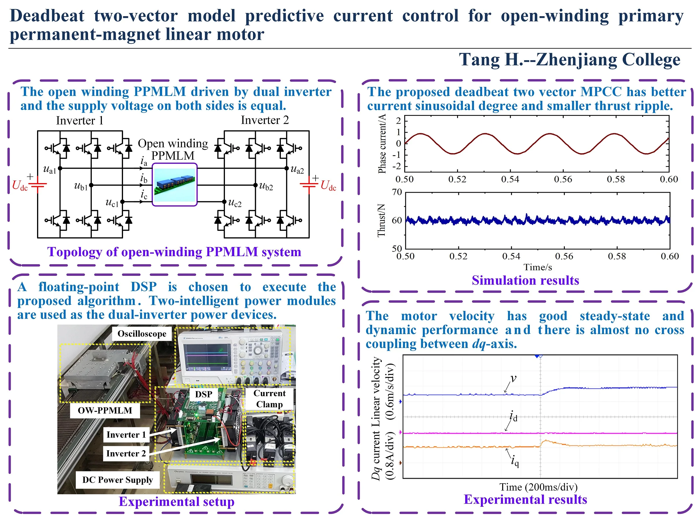
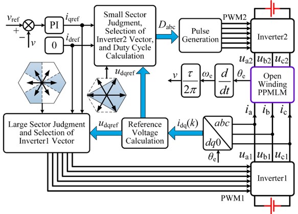
The open winding ppmlm system driven by dual inverter is shown in Fig. 1. In the figure, , and are the mover currents of ppmlm. , and are the output voltage of inverter 1. , and are the output voltage of inverter 2. is the DC bus voltage, and the supply voltage on both sides of this paper is equal [22].
Fig. 1Topology of open-winding PPMLM driven by dual-inverter
The voltage equation of open winding PPMLM in three-phase coordinate can be expressed as:
where is the resistance matrix, is inductance matrix. , and are the winding terminal voltage of open winding PPMLM, which is equal to the difference between the output voltage of inverter 1 and inverter 2. The Is the polar distance, is the linear velocity, is permanent magnet flux linkage, is the mover position angle, is winding resistance, is winding self-inductance, Is winding leakage inductance, is winding mutual inductance.
In order to simplify the mathematical model and facilitate the control, the voltage equation in the three-phase coordinate is equivalent transformed into the two-phase rotating coordinate through the rotating coordinate transformation theory:
where and are -axis current and -axis current respectively, and are -axis voltage and -axis voltage respectively. axis inductance .
The current equation of open winding PPMLM can be obtained from Eq. (2):
In the rotating coordinate, the electromagnetic torque of open winding PPMLM can be expressed as:
3. Dual inverter output voltage vector
In the dual inverter drive system shown in Fig. 1, the space voltage vector generated by inverter 1 and inverter 2 can be expressed as:
Therefore, the synthetic space voltage vector generated by the dual inverter can be expressed as:
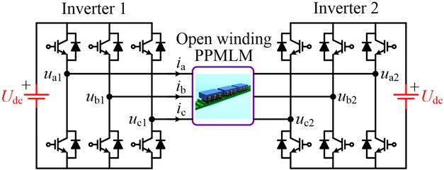
As can be seen from Eq. (5), inverter 1 can generate 8 switching states, thereby generating 8 space voltage vectors. The same is true for inverter 2. Further, according to Eq. (6), the dual inverter can generate 8 × 8 = 64 switching states, resulting in 64 synthetic space voltage vectors, as shown in Fig. 2.
Fig. 2Synthetic space vector distribution of dual-inverter
In Fig. 2, 64 synthetic vectors are distributed in 19 different spatial positions, corresponding to 18 non-zero vectors and 1 zero vector. Taking the spatial position G as an example, the synthetic voltage vector is 1'. Corresponding to the voltage vector (100) of inverter 1 and the voltage vector (011) of inverter 2 respectively. The synthetic space vector distribution of the whole dual inverter can be divided into six trapezoidal large sectors I-VI, and the centers of the large sectors are A-F respectively. As can be seen from Fig. 2, the space voltage vector distribution of the dual inverter is exactly the same as that of the three-level inverter. Therefore, better control performance can be obtained than that of the single inverter drive system.
4. Deadbeat two vector MPCC
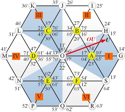
In order to improve the control performance of open winding PPMLM dual inverter drive system, a deadbeat two vector MPCC is proposed in this paper. Firstly, based on the deadbeat current control principle, the position of the large sector where the reference vector is located is determined. For example, when the reference vector is located in sector I, as shown in Fig. 3, the optimal vector produced by inverter 1 is , and the corresponding voltage vector is (100).
The reference vector can be synthesized by the reference vector and the reference vector . Therefore, when the vector is generated by one voltage vector of inverter 1, the vector can be approximated by two voltage vectors of inverter 2. In order to obtain the two optimal vectors and their duty cycle of inverter 2, the position of the small sector where the vector is located is further determined. For example, in Fig. 3, when is located in small sector (1), the non-zero vector (011) output by inverter 2, non-zero vector (001), zero vector (000) are three undetermined vectors. Finally, according to the action time of each vector, two optimal vectors are selected and their duty cycle is calculated to realize the proposed MPCC algorithm.
Fig. 3Principle of deadbeat two-vector MPCC
In order to implement proposed MPCC algorithm, first of all, the current equation shown in Eq. (3) needs to be discretized by first-order forward Euler:
According to the deadbeat current control principle, it is assumed that the -axis current and -axis current can track their reference values respectively at the end of each sampling period:
When the open winding PPMLM is controlled by 0, bring Eq. (8) into Eq. (7) to obtain the -axis and -axis reference voltages:
Transform and from two-phase coordinate system to two-phase coordinate system, available -axis and -axis reference voltage as follows:
To facilitate the judgment of large sectors, three auxiliary variables are defined:
Redefine variables:
where, is a symbolic function, and the output is 1 when 0. When 0, the output is 0. According to Eq. (12), when is 1, 2, 3, 4, 5 and 6, the corresponding large fan area codes are II, VI, I, IV, III and V respectively. According to the switching state of two-level three-phase inverter and the above large sector judgment method, the reference voltage and of inverter 2 in each large sector can be obtained, as shown in Table 1.
To facilitate small sector judgment, three auxiliary variables are defined:
Redefine variables:
According to Eq. (14), when is 1, 2, 3, 4, 5 and 6, the corresponding small fan area codes are II, VI, I, IV, III and V respectively. According to Eq. (13), Eq. (14) and Table 1, the action time of three vectors in each small sector of inverter 2 can be obtained, as shown in Table 2. In the table: represents the action time of the -th voltage vector of inverter 2, and represents the action time of the -th voltage vector of inverter 2. When 6, . When 6, 1. In addition, if 1, the unitary treatment is performed, .
Table 1Reference voltage components of inverter 2
Large sector | ||
I | ||
II | ||
III | ||
IV | ||
V | ||
VI |
Table 2Active times of voltage vectors of inverter 2
Small section | |||
I | |||
II | |||
III | |||
IV | |||
V | |||
VI |
Finally, the action times of , and are determined and the optimal vector is selected. The longer the action time of the voltage vector, the greater the impact on the control performance. Therefore, among the three vectors in each small sector of inverter 2, the two voltage vectors with large action time are the optimal vectors. In order to ensure that the sum of the action time of the two optimal vectors is the sampling period , the minimum action time is evenly distributed to the other two optimal vectors.
Further, a theoretical analysis of the proposed deadbeat two vector MPCC is presented here. For a model predictive control, a cost function is usually used to select the optimal vector. In the open-winding PPMLM drive system with MPCC algorithm, the cost function can be defined as:
As shown from Fig. 3, the vector combination (, ) in sector IV is used as an example to analyze the action time distribution principle of the proposed algorithm. The volt-second error caused by (, ) is:
where is the distribution factor of the action time of . Therefore, the square of can be expressed as:
As can be seen from Eq. (17), the error of is minimal when 0.5.
The duty cycle calculation of the two optimal vectors of inverter 2 is shown in Table 3.
Table 3Judgment of optimal vectors of inverter 2
Minimum action time | Optimal vector | Duty cycle |
, | , | |
, | , | |
, | , |
Fig. 4 is the control block diagram of the proposed deadbeat two vector MPCC, which is composed of coordinate transformation, reference voltage calculation, large sector judgment and optimal vector selection of inverter 1, small sector judgment and optimal two vector selection of inverter 2, pulse generation, etc. For the linear velocity outer loop control, the classical PI controller is still used for closed-loop regulation.
Fig. 4Block diagram of deadbeat two-vector MPCC for open-winding PPMLM
5. Simulation and experimental verification
In order to verify the correctness of the proposed deadbeat two-vector MPCC for open winding PPMLM drive system, the simulation analysis is carried out in the environment of MATLAB/Simulink, and the experimental verification is carried out on the prototype platform. The experimental platform is shown in Fig. 5. Motor parameters as follows: -axis inductance 85.2 mH, -axis inductance 85.2 mH, winding resistance 1.12 Ω, permanent magnet flux linkage 0.105 Wb, polar distance 14.7 mm, mover mass 32 kg.
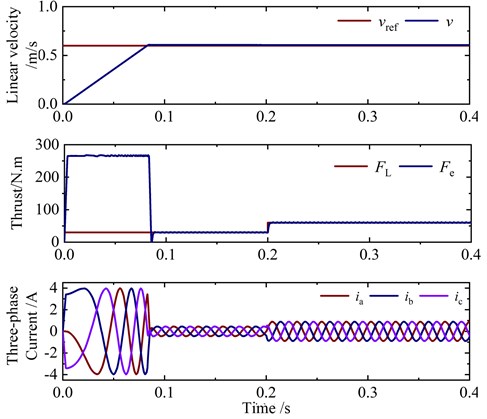
Fig. 6 shows the simulation waveform of linear velocity and current under rated thrust. At 0.2 s, the linear velocity suddenly changes from 0.3 m/s to 0.6 m/s. As can be seen from Fig. 6, the linear velocity of the motor can well track the reference value. In addition, when the linear velocity changes suddenly, the adjustment time is about 50 ms, indicating that the linear velocity can quickly track the reference value. Fig. 7 shows the simulation waveform of thrust and current at rated linear velocity. At 0.2 s, the load thrust suddenly changes from 30 N to 60 N. As can be seen from Fig. 7, the motor thrust can track the load thrust quickly and accurately. Because the proposed algorithm does not need current inner loop PI controller, there is almost no overshoot in the thrust response process. It can be seen that the proposed algorithm has good steady-state performance and dynamic performance.
Fig. 5Experimental setup of open-winding PPMLM
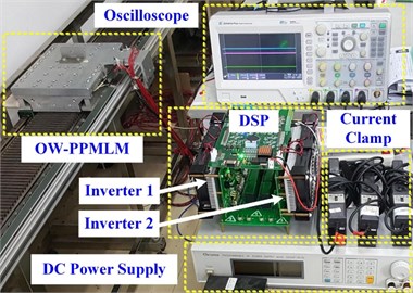
Fig. 6Simulation results with sudden velocity change
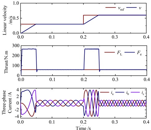
Fig. 7Simulation results with sudden thrust change
In order to verify the superiority of the proposed deadbeat two vector MPCC, the traditional MPTC, the traditional MPCC, and the proposed algorithm are compared and analyzed. Fig. 8 shows the simulation results of phase current and thrust of three control algorithms at 60 N thrust and 0.6 m/s linear velocity. In Fig. 8(a), the total harmonic distortion (THD) and thrust ripple of phase current are 8.81 % and 9.97 N respectively. In Fig. 8(b), the total harmonic distortion (THD) and thrust ripple of phase current are 4.54 % and 7.76 N respectively. In Fig. 8(c), the phase current THD and thrust ripple are 3.16 % and 4.86 N respectively. It can be seen that the proposed deadbeat two vector MPCC has better current sinusoidal degree and smaller thrust ripple.
Fig. 8Simulation comparison of conventional and deadbeat two-vector MPCCs
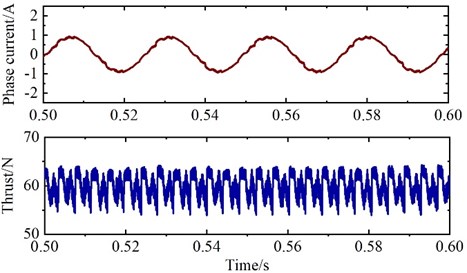
a) Traditional MPTC
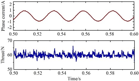
b) Traditional MPCC
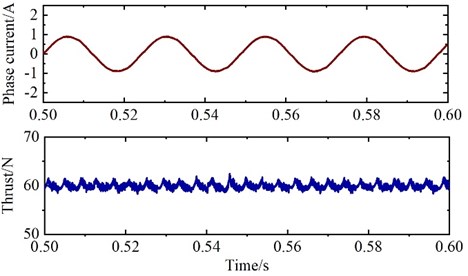
c) Deadbeat two vector MPCC
Fig. 9 shows the experimental results of open winding PPMLM deadbeat two-vector MPCC control system. It can be seen from the Fig. 9 that the three-phase current of the motor has good sinusoidal degree, and the linear velocity of the motor also has good steady-state and dynamic performance. In addition, from the -axis current waveform, it can be seen that there is almost no cross coupling between -axis in the dynamic process. Therefore, the proposed deadbeat two-vector MPCC has fast dynamic response.
Fig. 9Experimental results of deadbeat two-vector MPCC
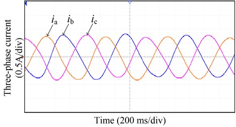
a) Three phase current waveform
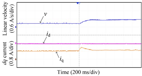
b) Linear velocity and -axis current waveform
In order to further verify the advantages of the deadbeat two-vector MPCC proposed in this paper, the phase current THD and thrust ripple of the traditional MPTC, the traditional MPCC, and the proposed deadbeat two vector MPCC under different linear velocities are tested on the experimental platform, as shown in Fig. 10.
Fig. 10Experimental comparison of conventional and deadbeat two-vector MPCCs
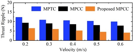
a) Thrust ripple
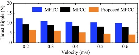
b) Current THD
It can be seen from the Fig. 10 that the proposed algorithm can effectively reduce the current harmonic and thrust ripple of open winding PPMLM, so as to reduce the motor loss and improve the system performance.
6. Conclusions
For the open winding PPMLM driven by dual inverter, a deadbeat two-vector MPCC is proposed in this paper. The proposed algorithm obtains the optimal voltage vector of the dual inverter through the deadbeat current control principle. Therefore, compared with the traditional MPTC and MPCC, the control complexity is greatly reduced and the problem of weight coefficient adjustment is avoided. Because inverter 2 has two optimal voltage vectors synthesized to approximate the reference vector in each switching cycle, it can effectively reduce the current harmonic distortion and thrust ripple, and improve the driving performance and system efficiency. Simulation and experimental results show the effectiveness of the proposed algorithm.
References
-
H. Tang, W. Zhao, and C. Gu, “a new adaptive control for five-phase fault-tolerant flux-switching permanent magnet motor,” International Journal of Rotating Machinery, Vol. 2016, No. 12, pp. 1–14, 2016, https://doi.org/10.1155/2016/3792645
-
Y. Du, M. Cheng, and K. T. Chau., “Design and analysis of a new linear primary permanent magnet Vernier machine,” Transactions of China Electrotechnical Society, Vol. 27, No. 11, pp. 22–30, 2012.
-
T. W. Ching, K. T. Chau, and W. Li, “Power factor improvement of a linear vernier permanent-magnet machine using auxiliary dc field excitation,” IEEE Transactions on Magnetics, Vol. 52, No. 7, pp. 1–4, Jul. 2016, https://doi.org/10.1109/tmag.2016.2524533
-
Y. Lee and J.-I. Ha, “Hybrid modulation of dual inverter for open-end permanent magnet synchronous motor,” IEEE Transactions on Power Electronics, Vol. 30, No. 6, pp. 3286–3299, Jun. 2015, https://doi.org/10.1109/tpel.2014.2325738
-
D. Sun, B. Lin, and W. Z. Zhou., “An overview of open winding electric machine system topology and control technology,” Transactions of China Electrotechnical Society, Vol. 32, No. 4, pp. 782–90, 2017.
-
M. Chen and D. Sun, “A unified space vector pulse width modulation for dual two-level inverter system,” IEEE Transactions on Power Electronics, Vol. 32, No. 2, pp. 889–893, Feb. 2017, https://doi.org/10.1109/tpel.2016.2585223
-
Z. Huang, T. Yang, P. Giangrande, S. Chowdhury, M. Galea, and P. Wheeler, “An active modulation scheme to boost voltage utilization of the dual converter with a floating bridge,” IEEE Transactions on Industrial Electronics, Vol. 66, No. 7, pp. 5623–5633, Jul. 2019, https://doi.org/10.1109/tie.2018.2873539
-
D. Sun et al., “Coordinate control of dual-inverter driven open-winding PMSM for hybrid electric vehicles,” Electric Machines and Control, Vol. 20, No. 2, pp. 29–35, 2016.
-
W. Hu, H. Nian, and T. Zheng, “Torque ripple suppression method with reduced switching frequency for open-winding PMSM drives with common DC bus,” IEEE Transactions on Industrial Electronics, Vol. 66, No. 1, pp. 674–684, Jan. 2019, https://doi.org/10.1109/tie.2018.2833803
-
H. Nian, Y. J. Zhou, and J. W. Li., “Control strategy of permanent magnet wind generator based on open winding configuration,” Electric Machines and Control, Vol. 17, No. 4, pp. 79–85, 2013.
-
Q. T. An, L. Sun, and L. Z. Sun., “Research on novel open-end winding permanent magnet synchronous motor vector control systems,” Proceedings of the CSEE, Vol. 35, No. 22, pp. 5891–5898, 2015.
-
Y. H. Li et al., “Adaptive variable voltage vectors switching table in direct torque control for PMSM,” Electric Machines and Control, Vol. 23, No. 9, pp. 75–83, 2019.
-
Y. Cheng, D. Sun, W. Chen, and H. Nian, “Model predictive current control for an open-winding PMSM system with a common DC bus in 3-D space,” IEEE Transactions on Power Electronics, Vol. 35, No. 9, pp. 9597–9607, Sep. 2020, https://doi.org/10.1109/tpel.2020.2972996
-
S. Vazquez, J. Rodriguez, M. Rivera, L. G. Franquelo, and M. Norambuena, “Model predictive control for power converters and drives: advances and trends,” IEEE Transactions on Industrial Electronics, Vol. 64, No. 2, pp. 935–947, Feb. 2017, https://doi.org/10.1109/tie.2016.2625238
-
F. Niu et al., “Model predictive flux control for permanent magnet synchronous motor,” Electric Machines and Control, Vol. 23, No. 3, pp. 34–41, 2019.
-
J. M. Liu et al., “Predictive current control of permanent magnet synchronous motor based on duty cycle modulation,” Proceedings of the CSEE, Vol. 645, No. 10, pp. 289–298, 2020.
-
H. Y. Tang, W. X. Zhao, and Q. W. Jiang., “Sliding mode control for five-phase flux switching permanent magnet motor,” Electric Machines and Control, Vol. 20, No. 20, pp. 51–58, 2016.
-
H. Tang and P. Tian, “Backstepping integral control for hydraulic servo system based on LuGre friction model,” Journal of Vibroengineering, Vol. 18, No. 8, pp. 5252–5265, Dec. 2016, https://doi.org/10.21595/jve.2016.17207
-
K. V. Praveen Kumar and T. Vinay Kumar, “Predictive torque control of open-end winding induction motor drive fed with multilevel inversion using two two-level inverters,” IET Electric Power Applications, Vol. 12, No. 1, pp. 54–62, Jan. 2018, https://doi.org/10.1049/iet-epa.2017.0209
-
K. M. Ravi Eswar, K. V. Praveen Kumar, and T. Vinay Kumar, “Modified predictive torque and flux control for open end winding induction motor drive based on ranking method,” IET Electric Power Applications, Vol. 12, No. 4, pp. 463–473, Apr. 2018, https://doi.org/10.1049/iet-epa.2017.0679
-
C. Sun, D. Sun, Z. Zheng, and H. Nian, “Simplified model predictive control for dual inverter-fed open-winding permanent magnet synchronous motor,” IEEE Transactions on Energy Conversion, Vol. 33, No. 4, pp. 1846–1854, Dec. 2018, https://doi.org/10.1109/tec.2018.2841012
-
X. Yuan, S. Zhang, C. Zhang, M. Degano, G. Buticchi, and A. Galassini, “Improved finite-state model predictive current control with zero-sequence current suppression for OEW-SPMSM drives,” IEEE Transactions on Power Electronics, Vol. 35, No. 5, pp. 4996–5006, May 2020, https://doi.org/10.1109/tpel.2019.2942156
-
X. Yuan, C. Zhang, and S. Zhang, “Torque ripple suppression for open-end winding permanent-magnet synchronous machine drives with predictive current control,” IEEE Transactions on Industrial Electronics, Vol. 67, No. 3, pp. 1771–1781, Mar. 2020, https://doi.org/10.1109/tie.2019.2907506
-
D. Xu, W. Zhao, H. Tang, X. Song, and R. Xue, “Three-vector-based model predictive current control with zero-sequence current suppression for open-winding LPMVM drives,” IEEE Transactions on Vehicular Technology, Vol. 70, No. 1, pp. 225–236, Jan. 2021, https://doi.org/10.1109/tvt.2020.3045257
-
Z.-H. Zhang, F. Min, G.-S. Chen, S.-P. Shen, Z.-C. Wen, and X.-B. Zhou, “Tri-partition state alphabet-based sequential pattern for multivariate time series,” Cognitive Computation, May 2021, https://doi.org/10.1007/s12559-021-09871-4
-
J. H. Asad, R. S. Hijjawi, A. Sakaji, and J. M. Khalifeh, “Resistance calculation for an infinite simple cubic lattice application of green’s function,” International Journal of Theoretical Physics, Vol. 43, No. 11, pp. 2223–2235, Nov. 2004, https://doi.org/10.1023/b:ijtp.0000049021.94530.6e
-
Z.-Z. Tan, J. H. Asad, and M. Q. Owaidat, “Resistance formulae of a multipurpose n-step network and its application in LC network,” International Journal of Circuit Theory and Applications, Vol. 45, No. 12, pp. 1942–1957, Dec. 2017, https://doi.org/10.1002/cta.2366
-
M. Q. Owaidat and J. H. Asad, “Resistance calculation of three-dimensional triangular and hexagonal prism lattices,” The European Physical Journal Plus, Vol. 131, No. 9, pp. 1–9, Sep. 2016, https://doi.org/10.1140/epjp/i2016-16309-x
About this article

This work was supported in part by the Jiangsu Natural Science Foundation of China (Project No. BK20191225) and Zhenjiang Key R&D Project (SH2020005).
