Abstract
The multi-power coupling transmission system (MPCTS) is an electromechanical coupling system, which typically use two or more induction motors to provide its driving torque. It is used in various industrial applications, such as cutter header driving systems of tunnel boring machinery, and yaw systems of wind turbines. In practical engineering applications, the loads borne by the MPCTS are very complex, including both torque loads and non-torque loads. Its dynamic characteristics are affected by both the gear transmission system and the drive motors. For this study, an electromechanical coupling dynamic model of the MPCTS, coupled with a gear transmission system, induction motor, and non-torque load, was constructed to analyze its dynamic characteristics under a non-torque load condition. The results showed increased offsets from the gear vibration equilibrium position, as well as deterioration in system load-sharing characteristics from increases in non-torque load and rotational speed. However, the influence of the non-torque load was significantly greater than that of the rotational speed.
Highlights
- An electromechanical coupling dynamic model of a multi-power coupling transmission system (MPCTS) is established.
- The influence of non-torque load and rotational speed on the dynamic characteristics of MPCTS are analyzed.
- With an increase in non-torque load, the offsets of vibration equilibrium positions of the central members almost increased linearly, the load-sharing characteristics of gear pairs deteriorated further.
- With an increase in rotational speed, the offsets of the vibration equilibrium position of the central members exhibit a parabolic-like trend. The load-sharing characteristics of gear pairs exhibit a very slow deterioration trend but accelerates further when the speed exceeds 1200 rpm.
- The influence of the non-torque load on the vibration equilibrium position and load-sharing characteristics is significantly greater than that of increased rotational speed.
1. Introduction
The multi-power coupling transmission system (MPCTS) is an electromechanical coupling system, which typically uses two or more induction motors to provide its driving torque. It is used in various industrial applications, such as cutter header driving systems of tunnel boring machinery, and yaw systems of wind turbines, because of its high dynamic performance, robustness, low cost, reliability, and efficiency [1, 2]. In practical engineering applications, MPCTS systems are used to provide high driving torque. However, the effects of loading from both the torque load and the non-torque, axial and radial loads, can be complex. During MPCTS operation, the non-torque load can lead to unequal loading between gears, and an increase in the dynamic meshing force among gear pairs, which negatively affect the dynamic characteristics and load-sharing properties of the system. This indicates that non-torque load is a major contributing factor in the safety and reliability of MPCTS operation, because it contributes to premature gear transmission system failures, and internal permanent damage [3]. Therefore, it is necessary to investigate the effects of non-torque load on MPCTS systems, in order to provide better theoretical guidance for system design. Researchers have recently begun to pay attention to the influence of non-torque loads on the dynamic characteristics of gear transmission systems. Tan et al. created a dynamic model of a wind turbine to investigate the effects of these loads on the performance of its drivetrain, bearing in mind the effects of non-torque loading caused by platform motion. The results suggest that the non-torque loads not only introduce additional excitation frequencies, but also increase the vibration amplitude of the drivetrain [4]. Likewise, Li et al. constructed a coupling model of a wind turbine drivetrain to analyze its dynamic characteristics under non-torque loads, caused by blade gravity, wind shear, tower shadow, and yawed inflow. Those results indicate that non-torque loads can lead to unequal planet load sharing, which are commonly carried by carrier 1 bearings [5]. Zhao et al. created a dynamic model of a helical gear system, to investigate the dynamic behaviors influenced by gear geometric eccentricity. It was found that there are sideband frequencies around the meshing frequency of gear pairs with geometric eccentricities [6]. Cao et al. built a dynamic model of a planetary gear set with four planets to analyze dynamic performance under non-torque loads caused by the gear eccentricities. This study points out that the non-torque loads caused by gear eccentricity error not only affect the dynamic response of the planetary gear set, but also deteriorate the load-sharing performance of the planetary gear set [7]. Zhai et al. studied the dynamic characteristics of one stage helical planetary gear system, under the influence of non-torque loading caused by errors in carrier assembly. The results show that those errors tend to increase the dynamic meshing forces of the gear pairs [8]. Park et al. developed two analysis models of a wind turbine gearbox, consisting of two different load configurations: one with both torque and non-torque loading, and the another with torque only loading. After investigating the influence of wind fluctuation on the load distribution of gear tooth flanks, along with the load sharing of planets, it was concluded that the influence of non-torque forces are very important to consider, to accurately determine the design load for a wind turbine gearbox [9]. Subsequently, Park et al. built a 3D analysis model of a three-point suspension gearbox for a 2-MW class wind turbine, to study the effects of axial force, radial force, and bending moment, on the load sharing of planet gears. The results show that the load sharing of planet gears is mainly affected by the non-torque factors of moment and radial force [10]. Choudhury and Tandon created a theoretical analysis model of a rotor bearing system to study its dynamic response under radial load conditions. They concluded that vibration amplitudes in both healthy and defective bearings increase with increasing speed but that those amplitudes are greater in defective bearings owing to radial load [11].
Qiu et al. developed a rotational-translational-axial dynamic model of a planetary gear transmission system, to investigate the effects of gravity, ring support stiffness, and bedplate tilt angle on the load-sharing characteristics of a planetary gear transmission system [12]. Zhu et al. created a dynamic model of a multi-floating gear system using the lumped parameter method, and analyzed the effects of a flexible pin on gear natural frequency and dynamic meshing force [13]. Wei et al. proposed a dynamic modeling method for a multistage planetary gear system by combining the lumped parameter and finite element methods (FEM). The dynamic response calculated by the proposed method was compared with the individual results calculated the individual methods. The results show that the accuracy of the proposed combination method is higher than that of the lumped parameter method, and lower than that of FEM, although the calculation efficiency is higher than that of FEM [14]. Frabco et al. developed a dynamic model of a planetary gearbox by combining the lumped parameter method and FEM, yielding very similar modal property results from simulation versus experimentation [15]. Zeng et al. built a nonlinear dynamic model of a gear-shaft-housing system by using FEM, to study the influence of the meshing and bearing support stiffness on vibration response. It was concluded that if the bearing support and meshing stiffness increase, the vibration acceleration and velocity of the housing also increase. However, the influence from the bearing stiffness is greater than that of the meshing stiffness [16]. Wang et al. created a coupled dynamic model of a spur, gear-shaft-bearing system, to investigate the effects of the shaft flexibility on bearing response and radiated noise [17].
In the aforementioned research studies, the focus is mainly on either dynamic characteristic of a system affected by non-torque loads, or a dynamic modeling method which only considers the characteristics of the gear transmission system itself. Subsequently, the effects of the time-varying excitations caused by the induction motor are ignored, although the mechanical and electric assemblies of the MPCTS cannot be divided into two non-correlated parts. Since the vibration caused by the time-varying meshing stiffness of the gear transmission system can be transmitted to the induction motor through the coupling, and the vibration caused by the speed or torque fluctuations of the motor can to be transmitted to the gear transmission system through the coupling. Therefore, in this study, an electromechanical coupling dynamic model of MPCTS with a gear transmission and induction motor, was used to analyze dynamic characteristic under non-torque loads. Section 2 presents the development of the MPCTS model used, while Section 3 details its resulting dynamic characteristics under a non-torque load condition. Section 4 presents the conclusions drawn on the basis of the analysis of the results.
2. Electromechanical coupling dynamic model for MPCTS
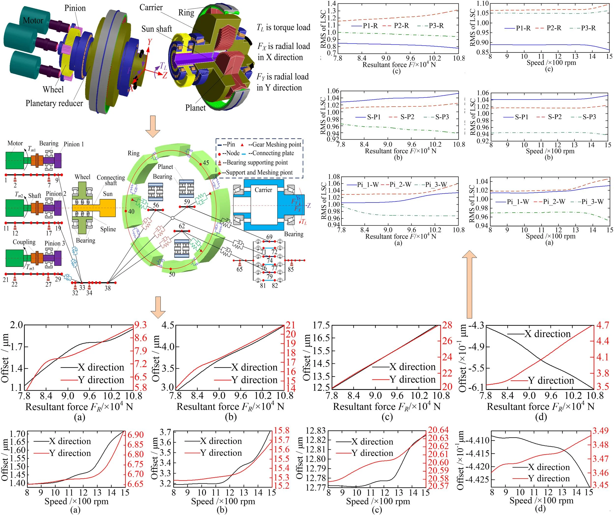
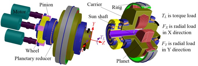
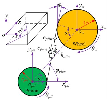
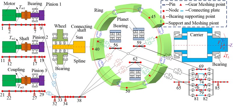
The MPCTS, as shown in Fig. 1, is composed of a single-stage planetary gear system and a parallel shaft gear system. In the parallel shaft gear system, the three pinions are driven separately by three induction motors, and the wheel is driven by the three pinions, which drive the wheel. The sun shaft is connected to the wheel via a spline, and the power from the wheel is transmitted to the single-stage planetary gear system through the sun shaft.
Fig. 1Three-dimensional-model of MPCTS
2.1. Dynamic model of Timoshenko beam
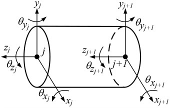
The dynamic model of the rotating shafts and gears was developed using the Timoshenko beam theory proposed by Nelson [18], and is shown in Fig. 2. The subscripts and represent the th pinion and ith gear pair formed by the th pinion and wheel, respectively. The subscript represents the wheel. The mathematical model of the two-node Timoshenko beam can be written as:
where denotes the mass matrix of the Timoshenko beam. and denote the damping matrix and stiffness matrix of the Timoshenko beam, and their detailed matrix forms are shown in Ref. [19]. and denote the displacement and exciting force column vectors of the Timoshenko beam.
Fig. 2Timsoshenko beam
2.2. Dynamic model of parallel shaft gear system
In the parallel shaft gear system, all the gears and shafts are equivalent to the Timoshenko beam. The basic parameters of the parallel shaft gear system are listed in Table 1. The dynamic model of the parallel shaft gear system can be obtained using the node finite element method, which is formed from the bearing, meshing gear pair, and shaft, as shown in Fig. 3(a). Nodes and are assumed to be the meshing nodes of the pinion-wheel gear pair. Nodes , , and are the bearing supporting points of the pinion and wheel, respectively. As shown in Eq. (2), the dynamic model of the supporting bearing can then be expressed in matrix form, using as the bearing supporting point in this example:
where and denote the damping matrix and stiffness matrix of the bearing, respectively. denotes the displacement vector of bearing supporting point . The detailed expressions of the matrices can be found in Ref. [20].
Fig. 3a) Finite element node diagram of parallel shaft gear system; b) meshing pair model of parallel shaft gear system
a)
b)
The meshing pair model of the parallel shaft gear system is shown in Fig. 3 (b), where the gear meshing pair is modeled as a stiffness-damping spring system, with the spring acting along the line of action between the two gears. The deformation along the line of action can be written as:
where , and denote the displacement of the pinion and wheel along the -, -, and -axes, respectively. and denote the angle displacement around the -axis and the base circle radius of the pinion and wheel, respectively. is the pressure angle, and is the position angle of the pinion. denotes the helix angle of the gear. is the transmission error, which can be expressed as:
where and are the th harmonic term amplitude and mean transmission error, respectively, and is the th pinion phase angle.
Hence, the differential equation of the pinion-wheel pair can be deduced as:
where and denote the mass and inertia of the pinion and wheel, respectively. and denote the input torque and load torque, while and denote the meshing damping and stiffness of the pinion-wheel pair, respectively. They can be expressed as Eq. (6):
where and are the th harmonic term amplitude and mean mesh stiffness, respectively. is the meshing damping ratio, represents the equivalent quality. Therefore, the matrix form of the pinion-wheel pair dynamic model can be written as:
where, is the meshing vector of the pinion-wheel pair, which can be written as:
where , , and denote the mass matrix, meshing damping matrix, and meshing stiffness matrix of the pinion-wheel pair, respectively. and denote the displacement and exciting force vectors, respectively. In Eq. (8), .
Table 1Basic parameters of parallel shaft gear system
Tooth number | Module/mm | Face width/mm | Pressure angle/° | Supporting stiffness/Nm-1 | Diameter/mm | |
Pinion | 19 | 4 | 146 | 20 | 1e8 | D1 = 100; D2 = 110; D3 = 160; D4 = 55; D5 = 50 |
Wheel | 99 | 4 | 146 | 20 | 1e8 |
2.3. Dynamic model of single-state planetary gear system
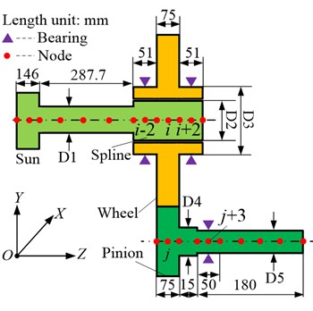
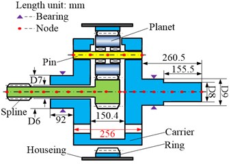
The dynamic model of a single-stage planetary gear system can also be obtained using the node finite element method, consisting of the bearing, sun-planet meshing pair, planet-ring meshing pair, pin, and carrier. The carrier, ring, planet, sun, and pin are modeled as different cross-section types of Timoshenko beams, and can be divided into different element nodes, as shown in Fig. 4(a). The basic parameters of the planetary stage are listed in Table 2. Herein, the dynamic model of the supporting bearing in a single-stage planetary gear system can be expressed using Eq. (2) as well.
Table 2Basic parameters of single-stage planetary gear system
Tooth number | Module / mm | Face width / mm | Pressure angle /° | Helix angle /° | Supporting stiffness / Nm-1 | Diameter/mm | |
Sun | 18 | 6 | 146 | 20 | 25.5 | 1e8 | D6 =260; D7 = 174.6; D8 = 268; D9 = 320 |
Planet | 52 | 6 | 146 | 20 | 25.5 | 1e9 | |
Ring | 123 | 6 | 146 | 20 | 25.5 | 1e10 |
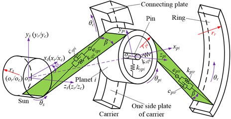
The meshing pair model of the single-stage planetary gear system is shown in Fig. 4(b). The subscripts , , , and represent the sun, ring, carrier, and th planet, respectively. There are two types of meshing pairs existing in the model: an external, sun-planet meshing pair, and an internal, planet-ring meshing pair. Without loss of generality, the external and internal meshing pairs are also modeled as a stiffness-damping spring system, with the spring acting along the line of action between the two gears.
For the sun-planet meshing pair, the deformation along the line of action can be written as:
where , and denote the displacement of the sun and planet along the -, -, and -axes, respectively. and denote the angle displacement around the -axis and the base circle radius of the sun and planet , respectively. represents the pressure angle, and represents the position angle of the planet. is the transmission error of the sun-planet meshing pair, which can be expressed as Eq. (15).
The differential equation of the sun-planet meshing pair can be deduced as follows:
where and denote the mass and inertia of the sun and planet , respectively. and denote the meshing damping and stiffness of the sun-planet meshing pair, and can be expressed as Eq. (15). denotes the input torque of the sun. The matrix form of the dynamic model of the sun-planet meshing pair can be written as:
where , , and denote the mass matrix, meshing damping matrix, and meshing stiffness matrix of the sun-planet pair, respectively. and denote the displacement and excitation force vectors, respectively. Moreover, is the meshing vector of the sun-planet meshing pair, which can be written as:
where .
Fig. 4a) dynamic model of single-stage planetary gear system; b) meshing pair model of single-stage planetary gear system
a)
b)
For the planet -ring meshing pair, the deformation along the line of action can be written as:
where , and denote the displacement of the ring along the -, -, and -axes, respectively. and denote the angle displacement around the -axis and the base circle radius of the ring, respectively. is the transmission error of the planet -ring meshing pair, which can be expressed as Eq. (15).
The differential equation of the planet -ring meshing pair can be deduced as follows:
where and denote the mass and inertia of the ring, respectively. and denote the meshing damping and stiffness of the planet -ring meshing pair, respectively, and can be expressed as Eq. (15):
(or , and ) and (or , and ) represent the th harmonic term amplitude and mean transmission error (or mean mesh stiffness), respectively. and represent the number of teeth in the ring and sun, respectively. represents the phase angle between planet (or ring) and sun (or planet ) meshing pair. and are the base pitch of the sun and planet , respectively. represents the phase difference between and . and are the phase relationships between the meshing pairs. represents the equivalent quality. The matrix form of the dynamic model of the planet -ring meshing pair can be written as follows:
where , , and denote the mass matrix, meshing damping matrix, and meshing stiffness matrix of the planet -ring meshing pair, respectively. and denote the displacement and excitation force vectors, respectively. Further, is the meshing vector of the planet -ring pair, which can be expressed as follows:
where .
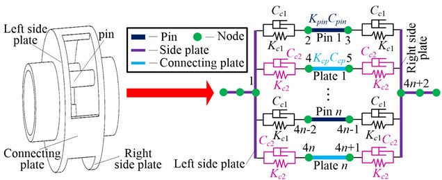
If it is assumed that the number of planets is in the planetary gear system (Fig. 5), it can be concluded that the number of pins and connections are also , respectively, according to the structural features of the planetary gear system. The stiffness-damping spring system is used to represent the coupled relationship between the side plate, pin, and connecting plate; and represent the coupling damping and stiffness between the side plate and pin, while and represent the coupling damping and stiffness between the side plate and connecting plate. and represent the damping and stiffness of the pin and connecting plate, respectively.
The matrix form of the dynamic model of the carrier pin can be expressed as:
where , and denote the mass matrix, damping matrix, and stiffness matrix of the carrier pin, respectively. and denote the displacement and exciting force vector of the carrier pin, respectively, and can be obtained using Eq. (13) and (14) in Ref. [19].
Fig. 5Dynamic model of carrier pin
2.4. Model of induction motor
Alternating current (AC) induction motors are frequently used in industrial applications, to provide the driving force for mechanical systems. Therefore, a three-phase AC induction motor with a rated power of 100 kW was used in this study. The basic parameters of the motor are shown in Table 3. The mathematical model of such a motor in the - coordinate system can be described as follows [21, 22].
Table 3Basic parameters of motor
Resistance / Ω | Rated speed / rpm | Voltage / V | Current / A | Leakage inductance / H | Rotating inertial / kg·m2 | Magnetizing inductance / H | |
Stator | 0.1749 | — | 1140 | 59.58 | 0.0048 | — | 0.2001 |
Rotor | 0.1954 | 1475 | — | 660 | 0.0048 | 10 | 0.2001 |
Eq. (19) shows the voltage and flux linkage equations:
where, represents the component of the stator/rotor voltage in the /-axis. represents the component of the stator/rotor current in the /-axis. denotes the resistance of the stator/rotor. denotes the stator/rotor self-inductance, and the mutual inductance between the stator and rotor, respectively. denotes the magnetic speed of the stator/rotor. Lastly, denotes the differential operator, while denotes the component of the stator/rotor flux linkage in the /-axis.
Eq. (20) shows the equations for both torque and motion:
where denotes the electromagnetic torque of the motor, denotes the number of winding pole pairs, denotes the coefficient of leakage inductance, and denotes the included angle between the stator flux leakage and rotor flux leakage. Lastly, denotes the load torque, while denotes the inertia of the rotor.
2.5. Electromechanical coupling dynamic model
Using the node finite element method and the structural features of MPCTS, the system can be divided into 88 nodes with 352 degrees of freedom. The entire stiffness matrix of the MPCTS can be obtained using the coupled method described in Ref. [20], and the distribution of nodes illustrated in Fig. 6; which shows the stiffness of the Timoshenko beam supporting the bearing and gear meshing.
Fig. 6Dynamic model of MPCTS
The MPCTS dynamic model can be developed after obtaining the mass matrix, stiffness matrix, damping matrix, and exciting force vector of each sub-element. The components of each sub-element matrix can be superimposed on the corresponding position of the total matrix [20], based upon the total number of system nodes, and the relationship between each node. In addition, the input torques act on nodes 1, 11, and 21, respectively, as the driving torques of the system. The radial loads , , and the torque load act on node 87. The master-slave control method was used to control the three induction motors, and the torque signal was selected as the control signal between the induction motors. Finally, the electromechanical coupling dynamic model of the MPCTS was be deduced as:
where , , and denote the mass, damping, and stiffness matrices of the MPCTS, respectively. and denote the displacement and exciting force column vectors of the MPCTS, respectively.
3. Result and discussion
Two load conditions were selected to investigate the influence of non-torque load on the dynamic characteristics of MPCTS: (a) the torque load , and (b) the non-torque, radial loads of and in addition to the torque load , which is shown in Fig. 7.
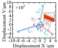
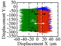
The motion trajectories of the pinions and the wheel are shown in Fig. 8. Geometrically, the motion trajectories of the pinions are linear, as shown in Fig. 8(a) and (b). Marked changes were observed in the angle () between trajectories and the length () of the trajectories. The difference between the angles is small under the torque load condition, where 120.0020°, 120.0007°, and 119.9973°, and the maximum angle difference is between and , namely, 0.0047°. A similar phenomenon also occurred in the length of trajectory under torque load condition, where 729.17 μm, 732.25 μm and 749.50 μm. The maximum length difference was between and , namely, 20.33 μm, as shown in Fig. 8(a). With regards to the effects of non-torque load, both the angle and the length vary significantly, but the length varied more, as shown in Fig. 8(b). Owing to the radial loads and the difference between the angles was further increased, where 120.7559°, 120.2356°, and 119.0085°. Notably, the maximum difference was still betwee n and , which is 1.7474°. Meanwhile, the lengths of trajectories increased to 1000 μm, 1200 μm and 791.44 μm, and increased by 270.89 μm, 467.75 μm and 41.94 μm, respectively, as compared to the torque load effects. However, some difference occurred when the maximum length difference was between and reaching 408.56 μm.
Fig. 7Load: a) torque load; b) non-torque load
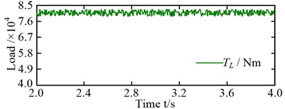
a)
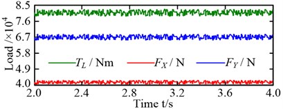
b)
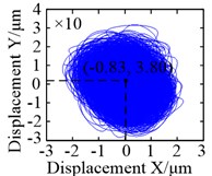
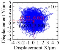
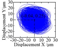
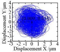
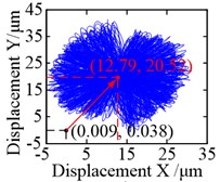
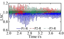
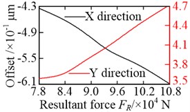
As shown in Fig. 8(c) and (d), the shape of the trajectory was close to a circle under either the torque load condition or the non-torque load condition. When non-torque load condition was considered, the vibration equilibrium positions of the wheel in and directions went from –0.83 μm to 1.22 μm, and from 3.80 μm to 6.02 μm – an increase of 2.47 and 0.58 times, respectively. Moreover, the load-sharing characteristics of the pinion-wheel gear pairs also changed significantly because of the change in the vibration equilibrium position, as shown in Fig. 9.
Fig. 8Motion trajectories: a) and b) motion trajectories of the pinions under torque load and non-torque load (the blue solid line, red dotted line and green dash-dotted line are the motion trajectories of pinion 1, pinion 2 and pinion 3, respectively); c) and d) motion trajectories of the wheel under torque load and non-torque load, respectively
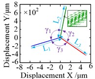
a)
b)
c)
d)
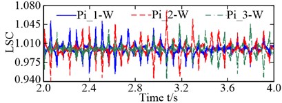
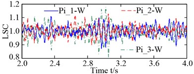
In this study, the maximum load-sharing coefficient (LSC) of the gear pair was selected to represent the LSC of the corresponding gear pair [23]. The LSC of the pinion-wheel gear pairs was 1.072 under torque load conditions, and 1.179 under non-torque load conditions – an increase of 9.98 %. In summary, non-torque load has a significant influence on both the vibration equilibrium positions of the pinions and the wheel, and the load-sharing characteristics of the pinion-wheel gear pairs.
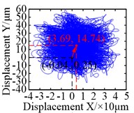
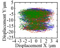
The motion trajectory of the sun was analogous to a circle, as shown in Fig. 10(a) and (b). Significant changes occurred in the vibration equilibrium position of the sun. When the non-torque load wass considered, the vibration equilibrium positions of it in both and directions were markedly offset, as compared with the torque load condition. They changed from –0.04 μm to 3.69 μm, and from 0.25 μm to 14.74 μm – increases of 93.25 and 57.96 times, respectively. In contrast, the motion trajectories of the planets were analogous to an ellipse under torque load condition, and their offsets of vibration equilibrium positions in and directions were about 0.20 μm and –10.52 μm, respectively, as shown in Fig. 10(c). In Fig. 10(d), there was an obvious difference, as the shapes of the motion trajectories of the planets were analogous to a rectangle under non-torque load condition, and their vibration equilibrium positions in the direction were offset in two different directions. For planet 3, the vibration equilibrium position was shifted in the negative direction of the -axis, with an offset of approximately 24.46 μm; increasing by 123.42 times. However, the vibration equilibrium positions for the other two planets were shifted in the positive direction of the -axis, and their offsets were 20.33 μm and 11.25 μm – increasing by 63.78 and 56.78 times, respectively. In addition, the vibration equilibrium positions of the planets in the direction were shifted in the negative direction of the -axis and change from approximately –10.52 μm to –163.66 μm – increasing by 14.56 times.
Fig. 9LSC: a) LSC of pinion-wheel gear pairs under torque load; b) LSC of pinion-wheel gear pairs under non-torque
a)
b)
Fig. 10Motion trajectories: a) and b) motion trajectories of the sun under torque load and non-torque load, respectively; c) and d) motion trajectories of the planets under torque load and non-torque load (the blue solid line, red dotted line and green dash-dotted line are the motion trajectories of planet 1, planet 2 and planet 3, respectively)
a)
b)
c)
d)
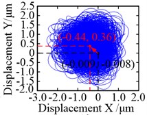
Fig. 11Motion trajectories: a) and b) motion trajectory of the carrier under torque load and non-torque load, respectively; c) and d) motion trajectory of the ring under torque load and non-torque load, respectively
a)
b)
c)
d)
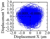
When the non-torque load was considered, the same held true in that the motion trajectories of the carrier and ring, and their vibration equilibrium positions, were hardly affected by it, as shown in Fig. 11. In addition, their motion trajectories were also analogous to a circle. Given that the ring is a fixed part, its restraint stiffness is set to be relatively large. As a result, there was an obvious difference in the offsets of the vibration equilibrium positions of the carrier in the and directions, as they were markedly larger than those of the ring. Compared with the torque load condition, the center of motion trajectory of the carrier changes from (0.009, 0.038) to (12.79, 20.52) when the non-torque load is considered. In other words, the offsets of their vibration equilibrium positions in the and directions are increased by 1420 and 539 times, respectively, as shown in Fig. 11(a) and (b). However, compared with Fig. 10(c) and (d), the offsets of the vibration equilibrium positions of the ring in the and directions are significantly reduced, and its center of motion trajectory goes from (–0.009, –0.008) to (–0.44, 0.36); increasing by 47.89 and 46 times.
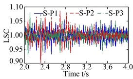
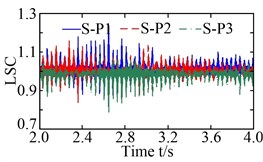
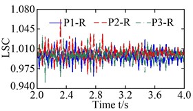
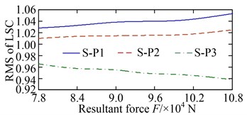
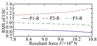
The load-sharing coefficients of the sun-planet gear pairs and planet-ring gear pairs are shown in Fig. 12. S-P ( 1, 2, and 3) in Fig. 12(a) and (b) represent the external meshing pair formed by the sun and the th planet, and P-R ( 1, 2, and 3) in Fig. 12 (c) and (d) denote the internal meshing pair formed by the th planet and ring. The vibration equilibrium positions of the sun, planets, ring, and carrier deviated significantly under the action of the radial loads and resulting in a deterioration of the load-sharing characteristics of the sun-planet gear pairs and planet-ring gearpairs. The load-sharing coefficients of the sun-planet gear pair and the planet-ring gear pair increased from 1.087 to 1.237, and from 1.062 to 1.189, increased by 13.80 % and 11.96 %, respectively. Obviously, the influence of the non-torque load on the load-sharing characteristics of the sun-planet gear pairs is greater than that of the planet-ring gear pairs. This is mainly caused by the offset of the vibration equilibrium position of the sun being larger than that of the ring.
Fig. 12Load-sharing coefficient (LSC): a) and b) LSC of sun-planet gear pairs under torque load and non-torque load, respectively; c) and d) LSC of planet-ring gear pairs under torque load and non-torque load, respectively
a)
b)
c)
d)
The variations in the vibration equilibrium position of each central member are listed in Table 4. Obviously, in addition to the ring, the offsets of the other central members in the direction are significantly greater than those in the direction, when the non-torque load is considered. This is because the radial load acting in the direction is significantly less than that in the direction, as shown in Fig. 7. However, it is noteworthy to mention that the increased multiple of the offset of the vibration equilibrium position in the direction is obviously higher than that of the direction. Moreover, the increased proportion of the offset of the vibration equilibrium position of the carrier is the largest, whether in the or direction, closely followed by the sun and the wheel. This is because the carrier is closest to the point of the load application, followed by the sun and wheel. Similar variations can be seen in the LSC of each gear pair, as listed in Table 5. This indicates that the closer the central members are to the point of the load application, the more their vibration equilibrium positions and load-sharing characteristics are affected by it.
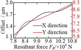
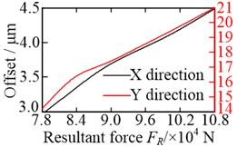
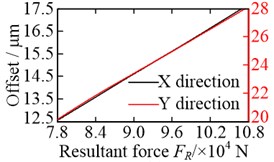
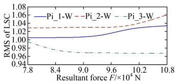
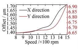
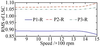
The offsets of the vibration equilibrium position of the central members at different non-torque loads are shown in Fig. 13. For convenience, the relationship between the resultant force and the offset, shown in the figure, where . It is clear that the offsets of the vibration equilibrium position increase almost linearly with the increase in the resultant force . Whether in the or direction, the vibration equilibrium positions of the wheel, sun, and carrier are shifted in the positive direction of either the -axis or -axis, with an increase in the resultant force , as shown in Fig. 13(a), (b), and (c). However, with the increase in the resultant force , the vibration equilibrium position of the ring in the direction is shifted in the negative direction of the -axis, but the vibration equilibrium position of the ring in the direction is shifted in the positive direction of the -axis, as shown in Fig. 13(d). As a result, the load-sharing characteristics of all gear pairs deteriorate further with the increase in the resultant force , as shown in Fig. 14.
Table 4Variation of vibration equilibrium position of each central member
Offset of vibration equilibrium position in direction / μm | Offset of vibration equilibrium position in direction / μm | |||||||
Central member | Central member | |||||||
Load condition | Wheel | Sun | Carrier | Ring | Wheel | Sun | Carrier | Ring |
Torque load | –0.83 | –0.04 | 0.009 | –0.009 | 3.80 | 0.25 | 0.038 | –0.008 |
Non-torque load | 1.22 | 3.69 | 12.79 | –0.44 | 6.02 | 14.74 | 20.52 | 0.36 |
Increased multiple | 2.47 | 93.25 | 1420 | 47.89 | 0.58 | 57.96 | 539 | 46 |
Table 5Variation of load-sharing coefficient of each gear pair
Load-sharing coefficient | |||
Load condition | Pinion-wheel gear pairs | Sun-planet gear pairs | Planet-ring gear pairs |
Torque load | 1.072 | 1.087 | 1.062 |
Non-torque load | 1.179 | 1.237 | 1.189 |
Increased proportion | 9.98 % | 13.80 % | 11.96 % |
Fig. 13Offset of vibration equilibrium position at different non-torque loads: a) wheel; b) sun; c) carrier; and d) ring
a)
b)
c)
d)
Fig. 14Root mean square (RMS) of LSC at different non-torque loads: a) pinion-wheel gear pairs; b) sun-planet gear pairs; c) planet-ring gear pairs
a)
b)
c)
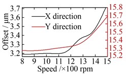
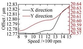
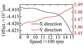
Fig. 15Offset of vibration equilibrium position at different speeds: a) wheel; b) sun; c) carrier; d) ring
a)
b)
c)
d)
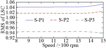
Fig. 16RMS of LSC at different speeds: a) pinion-wheel gear pairs; b) sun-planet gear pairs; c) planet-ring gear pairs
a)
b)
c)
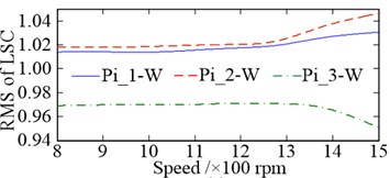
The offsets of the vibration equilibrium position of the central members at different speeds are shown in Fig. 15. When compared with Fig. 13, similarities can be observed. However, with the increase in the rotational speed, the offsets of the vibration equilibrium position of all the central members exhibit an approximate parabolic trend. When the rotational speed changes reaches the range of 800-1200 rpm, the offsets of the vibration equilibrium position of all central members increase slowly. The load-sharing characteristics of all gear pairs exhibit a very slow deterioration trend as well. Once the rotational speed exceeds 1200 rpm, the offsets of the vibration equilibrium position of the central members increase rapidly with the increase in speed, and the deterioration trend accelerates further, as shown in Fig. 16. In addition, the comparisons between Fig. 13 with Fig. 15, and Fig. 14 with Fig. 16, shows that the influence of non-torque load on the vibration equilibrium position and load-sharing characteristics is significantly greater than that of the rotational speed.
4. Conclusions
In this study, an electromechanical coupling dynamic model of the MPCTS, based upon the node finite element method, was established considering motor characteristics. The dynamic characteristics of the MPCTS are investigated under non-torque load conditions, and include a detailed study of the resulting motion trajectories and load-sharing characteristics. Based on the simulations and discussions, the following conclusions were drawn:
1) The motion trajectories of the pinions are linear. The angles and the lengths between the trajectories increase in different degrees when the non-torque load is considered. Here, the maximum angle deference and the maximum length deference increased from 0.0047° to 1.7474°, and from 20.33 μm to 408.56 μm, respectively. The motion trajectories of the wheel, sun, carrier, and ring are analogous to a circular shape. The motion trajectory of the planet is almost elliptical in shape, under the torque load condition, but is analogous to more rectangular under non-torque load condition. In addition, when the non-torque load is considered, the offsets of the vibration equilibrium position of the central members increase significantly, and the offsets in the direction are noticeably greater than those in the direction.
2) For the central members, under the non-torque load condition, the increased multiples of their offsets of vibration equilibrium positions in the direction are clearly higher than those in the direction. The closer the central members are to the applied load, the greater the increase in offset of the vibration equilibrium position of the carrier, closely followed by the sun and wheel. Similar characteristics were also observed in the load-sharing coefficient of each gear pair.
3) With an increase in the non-torque load, the offsets of the vibration equilibrium positions of the central members almost increased linearly, and the load-sharing characteristics of all gear pairs deteriorated further. However, with an increase in rotational speed, the offsets of the vibration equilibrium position of the central members exhibit a parabolic-like trend. When rotational speed is within the 800-1200 rpm range, the offsets increase slowly. However, once the rotational speed exceeds 1200 rpm, the offsets increase rapidly. Similarly, when the rotational speed is within the 800-1200 rpm range, the load-sharing characteristics of all gear pairs exhibit a very slow deterioration trend but accelerates further when the speed exceeds 1200 rpm. Moreover, the influence of the non-torque load on the vibration equilibrium position and load-sharing characteristics is significantly greater than that of increased rotational speed.
References
-
E. S. Ali, “Speed control of induction motor supplied by wind turbine via Imperialist Competitive Algorithm,” Energy, Vol. 89, pp. 593–600, Sep. 2015, https://doi.org/10.1016/j.energy.2015.06.011
-
M. H. Marzebali, S. H. Kia, H. Henao, G.-A. Capolino, and J. Faiz, “Planetary gearbox torsional vibration effects on wound-rotor induction generator electrical signatures,” IEEE Transactions on Industry Applications, Vol. 52, No. 6, pp. 4770–4780, Nov. 2016, https://doi.org/10.1109/tia.2016.2600599
-
Guo, Y., J. Keller, and W. Lacava, “Combined effects of input torque, non-torque load, gravity, and bearing clearance on planetary gear load share in wind turbine drivetrains,” National Renewable Energy Laboratory, NREL Report No. CP-5000-55968, 2012.
-
J. Tan, C. Zhu, C. Song, Y. Li, and X. Xu, “Dynamic modeling and analysis of wind turbine drivetrain considering platform motion,” Mechanism and Machine Theory, Vol. 140, pp. 781–808, Oct. 2019, https://doi.org/10.1016/j.mechmachtheory.2019.06.026
-
Z. Li, B. Wen, Z. Peng, X. Dong, and Y. Qu, “Dynamic modeling and analysis of wind turbine drivetrain considering the effects of non-torque loads,” Applied Mathematical Modelling, Vol. 83, pp. 146–168, Jul. 2020, https://doi.org/10.1016/j.apm.2020.02.018
-
B. Zhao, Y. Huangfu, H. Ma, Z. Zhao, and K. Wang, “The influence of the geometric eccentricity on the dynamic behaviors of helical gear systems,” Engineering Failure Analysis, Vol. 118, p. 104907, Dec. 2020, https://doi.org/10.1016/j.engfailanal.2020.104907
-
Z. Cao, Y. Shao, M. Rao, and W. Yu, “Effects of the gear eccentricities on the dynamic performance of a planetary gear set,” Nonlinear Dynamics, Vol. 91, No. 1, pp. 1–15, Jan. 2018, https://doi.org/10.1007/s11071-017-3738-0
-
H. Zhai, C. Zhu, C. Song, H. Liu, and H. Bai, “Influences of carrier assembly errors on the dynamic characteristics for wind turbine gearbox,” Mechanism and Machine Theory, Vol. 103, pp. 138–147, Sep. 2016, https://doi.org/10.1016/j.mechmachtheory.2016.04.015
-
Y.-J. Park, G.-H. Lee, J.-S. Song, and Y.-Y. Nam, “Characteristic analysis of wind turbine gearbox considering non-torque loading,” Journal of Mechanical Design, Vol. 135, No. 4, p. 04450, Apr. 2013, https://doi.org/10.1115/1.4023590
-
Y.-J. Park, G.-H. Lee, J.-S. Oh, C.-S. Shin, and J.-S. Nam, “Effects of non-torque loads and carrier pinhole position errors on planet load sharing of wind turbine gearbox,” International Journal of Precision Engineering and Manufacturing-Green Technology, Vol. 6, No. 2, pp. 281–292, Apr. 2019, https://doi.org/10.1007/s40684-019-00059-8
-
A. Choudhury and N. Tandon, “Vibration response of rolling element bearings in a rotor bearing system to a local defect under radial load,” Journal of Tribology, Vol. 128, No. 2, pp. 252–261, Apr. 2006, https://doi.org/10.1115/1.2164467
-
X. Qiu, Q. Han, and F. Chu, “Load-sharing characteristics of planetary gear transmission in horizontal axis wind turbines,” Mechanism and Machine Theory, Vol. 92, pp. 391–406, Oct. 2015, https://doi.org/10.1016/j.mechmachtheory.2015.06.004
-
C. Zhu, X. Xu, H. Liu, T. Luo, and H. Zhai, “Research on dynamical characteristics of wind turbine gearboxes with flexible pins,” Renewable Energy, Vol. 68, pp. 724–732, Aug. 2014, https://doi.org/10.1016/j.renene.2014.02.047
-
J. Wei et al., “A coupling dynamics analysis method for a multistage planetary gear system,” Mechanism and Machine Theory, Vol. 110, pp. 27–49, Apr. 2017, https://doi.org/10.1016/j.mechmachtheory.2016.12.007
-
F. Concli, L. Cortese, R. Vidoni, F. Nalli, and G. Carabin, “A mixed FEM and lumped-parameter dynamic model for evaluating the modal properties of planetary gearboxes,” Journal of Mechanical Science and Technology, Vol. 32, No. 7, pp. 3047–3056, Jul. 2018, https://doi.org/10.1007/s12206-018-0607-9
-
W. Zeng, X. Z. Zhu, and Z. J. Wei, “Study on nonlinear dynamic response of the gear-shaft-housing coupling system,” Applied Mechanics and Materials, Vol. 26-28, pp. 805–808, Jun. 2010, https://doi.org/10.4028/www.scientific.net/amm.26-28.805
-
S. Wang, A. Xieeryazidan, X. Zhang, and J. Zhou, “An improved computational method for vibration response and radiation noise analysis of two-stage gearbox,” IEEE Access, Vol. 8, pp. 85973–85988, 2020, https://doi.org/10.1109/access.2020.2990938
-
H. D. Nelson, “A finite rotating shaft element using Timoshenko beam theory,” Journal of Mechanical Design, Vol. 102, No. 4, pp. 793–803, Oct. 1980, https://doi.org/10.1115/1.3254824
-
R. Shu, J. Wei, R. Tan, X. Wu, and B. Fu, “Investigation of dynamic and synchronization properties of a multi-motor driving system: Theoretical analysis and experiment,” Mechanical Systems and Signal Processing, Vol. 153, p. 107496, May 2021, https://doi.org/10.1016/j.ymssp.2020.107496
-
Z. Hu, J. Tang, J. Zhong, and S. Chen, “Frequency spectrum and vibration analysis of high speed gear-rotor system with tooth root crack considering transmission error excitation,” Engineering Failure Analysis, Vol. 60, pp. 405–441, Feb. 2016, https://doi.org/10.1016/j.engfailanal.2015.11.021
-
M. S. Zaky, “High performance DTC of induction motor drives over a wide speed range,” Electrical Engineering, Vol. 97, No. 2, pp. 139–154, Jun. 2015, https://doi.org/10.1007/s00202-014-0321-2
-
T. Ramesh, A. Kumar Panda, and S. Shiva Kumar, “Type-2 fuzzy logic control based MRAS speed estimator for speed sensorless direct torque and flux control of an induction motor drive,” ISA Transactions, Vol. 57, pp. 262–275, Jul. 2015, https://doi.org/10.1016/j.isatra.2015.03.017
-
W. Sun, X. Li, J. Wei, A. Zhang, X. Ding, and X. Hu, “A study on load-sharing structure of multi-stage planetary transmission system,” Journal of Mechanical Science and Technology, Vol. 29, No. 4, pp. 1501–1511, Apr. 2015, https://doi.org/10.1007/s12206-015-0323-7
About this article

This research is supported by the National Natural Science Foundation of China (51905060/52005067/51905062 /51905064/51805060/51875068); China Postdoctoral Science Foundation (2021M700619); National Key Research and Development Project of China (2020YFB2010100); Natural Science Foundation Project of Chongqing Science and Technology Commission (cstc2020jcyj-msxmX0346/cstc2019jcyj-msxmX0733); Science and Technology Research Program of Chongqing Municipal Education Commission (KJQN201901107/KJQN201901112/KJQN201901115). We also want to thank the support from the Scientific Research Foundation of Chongqing University of Technology, China.
