Abstract
The complexity of single-loop gear system transmission structure makes it difficult for traditional modeling methods to establish precise dynamic model, which greatly affects the accuracy of its dynamic characteristics research. Firstly, a structure diagram is established by adopting modularization idea according to the structural properties of single-loop gear system. On this basis, a precise bond graph model of the single-loop gear system is obtained combining the modeling principle of bond graph method and the advantages of rich graphics library. Secondly, the dynamic state equation of single-loop gear system is obtained from bond graph model. The simulation model of gear system is established by numerical simulation method. Eventually, the dynamic characteristics of a single-loop gear system are acquired by calculating two dynamic indexes of the system under linear and weakly nonlinear states. The simulation results show that the bond graph method can accurately describe the mathematical model of single-loop gear train and master the dynamic characteristics of complex gear train. This will provide a reference for the structural design and dynamic characteristics of the transmission system.
1. Introduction
Gears and gear products are important basic components of mechanical equipment. The main transmission parts of complete mechanical equipment are mostly gear transmission [1, 2]. With the rapid development of science and technology, the annual sales volume of gear industry has exceeded hundreds of billions RMB, forming a diversified coexistence of enterprises and common development of the industry pattern [3, 4]. In addition, as low-carbonization has become the theme of global manufacturing development, energy conservation and emission reduction will be the direction of technological development faced by enterprises all over the world. The industry should seize the opportunity of low-carbon economy and intervene in the research of new transmission technologies such as hybrid power and stepless speed regulation in advance [5]. In order to better meet the current application requirements, the new gear transmission system composed of gears and gear products is developing towards miniaturization and cyclization, resulting in more complicated structural changes [6, 7]. The kinematics and dynamics of the system have also become extremely complex. Therefore, traditional modeling methods are difficult to accurately obtain the dynamic behavior of the system. Such as, the dynamic load-sharing characteristics of aircraft face gear dual-power split transmission system are taken as the research object. Considering the factors of time-varying meshing stiffness, comprehensive error, backlash, support clearance, spline clearance, torsional stiffness, and support stiffness, the dynamic load-sharing model was constructed based on the lumped-parameter method [8]. Moreover, the time consuming, laborious, and intuitive nature of those methods leads to long development cycles for gear systems [9, 10].
At present, the research of precise modeling method for complex gear transmission system is still a hot topic [11-13]. New modeling methods include graph theory, signal flow diagram and bond graph [14-17]. The graph theory is to introduce the similarity between the network principle of graph topology and the power flow transmission of mechanical system into the mechanical structure modeling. This method used to study the dynamic characteristics of gear transmission system can not only overcome the shortcomings of traditional modeling methods but also improve the design quality. It can intuitively and clearly display the transmission mechanism of each gear coupling characteristics in the gear system [18, 19]. However, its equivalent rules and modeling theory have not formed a unified theoretical system, so the dynamic characteristics of gear system has not been accurately elucidated. Based on the similarity of power flow direction and transmission of gear system, the signal flow diagram method utilizes equivalent rules to establish kinematic model of gear systems. This method can better reflect the kinematic characteristics of the complex gear system, but cannot reflect the mechanical characteristics. In addition, the theoretical system of signal flow diagram modeling is not perfect. The theoretical system of bond graph modeling method is relatively mature and has a rich library of graphic elements. It can be used to set up mathematical models of various nonlinear factors of inter-tooth system, reflecting the dynamic characteristics of gear train more truly [20, 21].
In addition, bonding graph modeling has been widely used in the field of machinery. Such as, the Bond Graph methodology is originally employed to obtain a per-unitized dynamic model for a wind turbine two-mass drive train. Bond Graph is a formal multi-domain methodology that strongly enforces the energy conserving property. A natural outcome of applying this methodology is a reliable and dimensionally homogeneous per-unit dynamic model. This methodology is utilized to address the lack of dimensional homogeneity in some drive train models that are being used in the wind energy literature [22]. The aim of this article is to present an efficient dynamical model for simulating flapping robot performance employing the bond graph approach. For this purpose, the complete constitutive elements of the system under investigation, including the main body and accessories, flapping mechanism, flexible wings and propulsion system consisting of a battery, DC motors and gear boxes, are considered. A complete model of the system was developed appending bond graph models of the subsystems together utilizing appropriate junctions. SimMechanics toolbox of MATLAB software was used to investigate whether the equations obtained from the bond graph were extracted correctly and whether the relationships between all the subsystems are maintained so that they lead to a logical motion for the flapping wing. The very good agreement between the results achieved from various models illustrates the validity and accuracy of the proposed bond graph model [23]. When the precise mathematical model is established of gear train, the dynamic behavior of vibration characteristics and stability of the motion system can be truly grasped [24-27].
According to the advantages of bond graph modeling method and combined with the structural properties of gear transmission system, an accurate dynamics model of single-loop gear system is established by bond graph method in this paper. The dynamic characteristics of this system under linear and weakly nonlinear states are studied. The relevant research results of this paper will provide guidance for the design concept of new gear transmission system, or provide theoretical reference for the design of complex loop system.
2. Establishment of analysis model for single-loop gear system
2.1. Structural model
2.1.1. Fixed shaft gear module
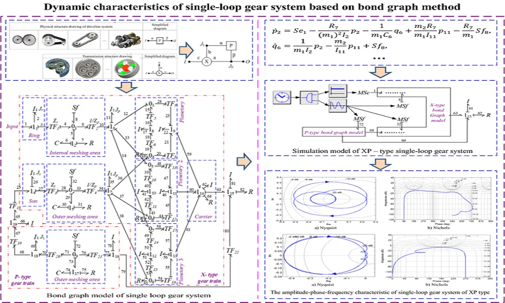
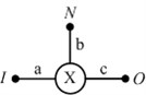
Fixed axle gear train module is the most basic and simplest gear transmission unit, also known as basic gear system. Its main characteristics are: the element body has and only 1 degree of freedom; Integrated input, output shaft each one; the initial position of the axis line of each gear always remains unchanged. According to the simplified rule of transforming the gear transmission system into an equivalent transmission structure diagram in literature [28, 29], the structure diagram of the fixed-shaft gear module is constructed, as shown in Table 1. Where, "□" represents the image diagram of gear box, is the code of the fixed shaft unit body, and are the input and output ends of the unit body, and are the equivalent input and output shafts of the unit body. The fixed shaft gear train unit body is referred to as P unit body. It is likely to a pair of meshing gears, or a complex fixed shaft gear train.
2.1.2. Planetary gear module
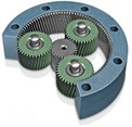
Planetary gear module is also the most basic, and simplest transmission unit, also known as differential gear system. Its main characteristics are: the element body has two degrees of freedom; there are three shafts connected with the turnover unit body; The element body has differential characteristics. Similarly, the construction method of the structure diagram of planetary gear train unit is the same as that of fixed-axis unit, as shown in Table 2. Where, "○" represents the image diagram of a single row of planetary discs, is the code of the turnover unit body, , and are the three shaft ends of the turnover unit body respectively, and , and are the equivalent drive shafts (basic components) of the turnover unit body respectively. This type of planetary gear train element can also be called element. For practical use, such as two inputs and one output, unit body in this case constituted a confluence output mechanism. Conversely, there may be two outputs and one input, and the element body in this case constitutes a shunt output mechanism.
Table 1Structural chart of fixed shaft gear element
Physical structure drawing of driveline system | Simplified diagram | ||||
 |  |  | … |  | 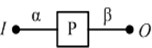 |
Table 2Structural chart of planetary gear element
Transmission structure drawing | Simplified diagram | |||
 |  | … |  |  |
2.1.3. Structural model of single-loop gear system
As shown in Table 3, the structure chain diagram of single-loop and single degree of freedom (DOF) gear transmission system, XP type is composed of a set of basic gear train of DOF fixed axle element body and a set of differential gear train of 2 DOF turnover element body.
Table 3Structural chain graph of single-loop gear transmission system
The name of structure | Chain structure diagram | Provided |
XP | 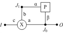 | Output confluence type |
Note: in Table 3, and are mechanical connection nodes; Other characters have the same meanings as the preceding ones | ||
2.2. Dynamic model
2.2.1. Dynamic model of fixed axis module
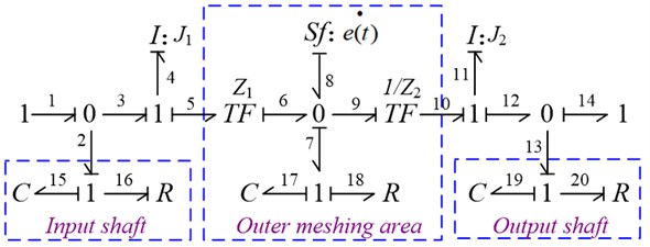
According to the bond graph modeling principle, the fixed-axis module model is established, as shown in Fig. 1.
Fig. 1Bond graph model of fixed axis module
2.2.2. Dynamical models of planetary modules
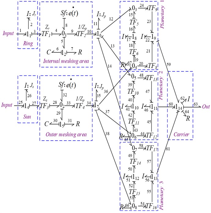
Under such conditions, the bond graph model of planetary gear modules is obtained, as shown in Fig. 2.
Fig. 2Bond graph model of planetary module
2.2.3. Dynamic model of single-loop gear system
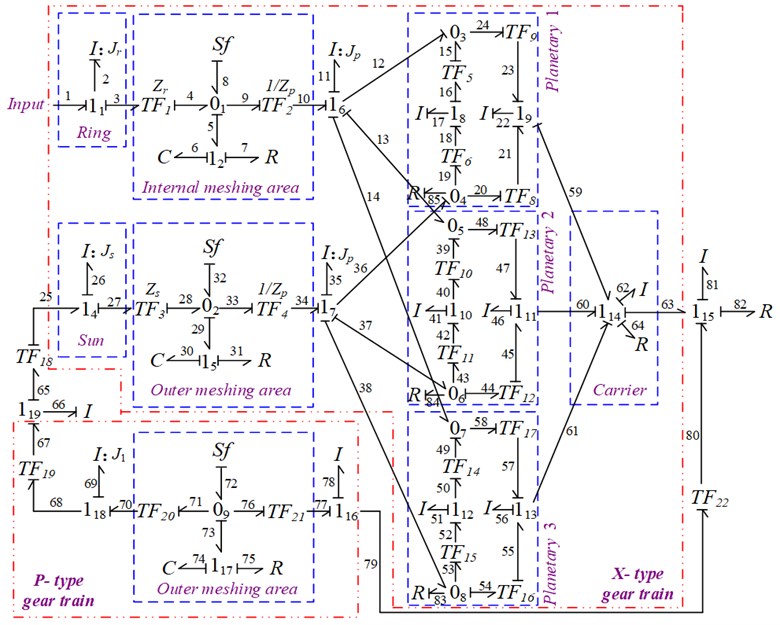
Based on the bond graph model of fixed axis module and planet module, and combined with the structural characteristics of XP single-loop gear system, the dynamics model of the gear train was established by bond graph method, as shown in Fig. 3.
Fig. 3Bond graph model of single loop gear system
3. Equation of state for single-loop gear system
The basic form of the state equation of its dynamic system is be written as shown in Eq. (1):
where, (1, 2, …, ) is the state variable; ( 1, 2, …, ) is an input variable to the system; is an algebraic function; is time variable.
The state variables of XP single-loop gear train are composed of , and , , , , , , , . Similarly, the state equation of the gear train is obtained, as shown in Eqs. (2-9):
where, is the conversion coefficient of the converter, 1, 2,…, 22; is the potential source of the input; , and are steady-state transmission errors.
4. Simulation analysis
4.1. The simulation conditions
4.1.1. Simulation condition setting
According to the bond graph model of XP type single-loop gear train given in Fig. 3 and combined with the setting requirements of numerical simulation software, the simulation model as shown in Fig. 4 is constructed. In this figure, keys 8, 32 and 72 are the steady-state transmission errors of internal and external engagement of x-type element and external engagement of P-type element respectively, and the derivative of this quantity is used as a variable flow source element to simulate. The potential source element is used to simulate the input torque to the system.
Fig. 4Simulation model of XP – type single-loop gear system
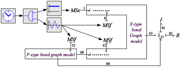
Similarly, the setting of simulation parameters of XP single-loop gear train combines the simulation parameters of X type and P type element body.
Table 4Simulation parameter
Number of teeth | 19, 31, 81 | Radius of indexing circle | 0.0285 m, 0.0465 m, 0.1215 m, 0.075 m |
Moment of inertia | 0.0015 Kg·m2 0.0094 Kg·m2 0.1510 Kg·m2 0.0491 Kg·m2 | Meshing stiffness | 1.8e8 N/m |
Torsional stiffness of shaft | 2.0e8 N/m | ||
Moment of inertia of shaft | 0.0036 Kg·m2 | ||
Meshing damping | 2000 N·s·m-1 | Support damping | 1800 N·s·m-1 |
Derivative of steady state transmission error | |||
4.2. Results of linear system analysis
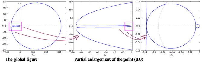
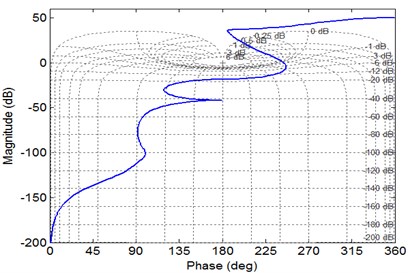
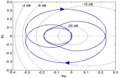
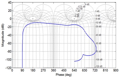
According to the Nyquist diagram shown in Fig. 5(a), the open-loop frequency characteristic curve of the system does not enclose the point (–1, ) and passes through the positive real axis twice clockwise, so the system is unstable according to the Nyquist stability criterion. At the same time, it can be seen from the local magnification of Nyquist diagram that the phase diagram of open loop system does not pass through the origin. Nichols diagram as shown in Fig. 5(b), the vertical axis is the logarithm of amplitude and the horizontal axis is the phase Angle, which reflects the changing relationship between amplitude and phase Angle. The figure, further demonstrates that the closed loop system of XP single loop gear system is unstable under such simulated conditions.
4.3. Analysis results of weakly nonlinear systems
4.3.1. Dynamic characteristics of single-loop gear system
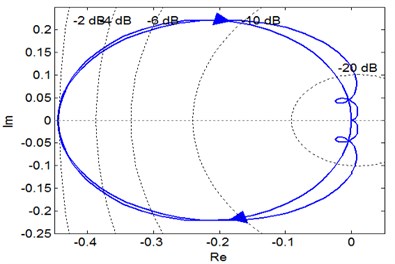
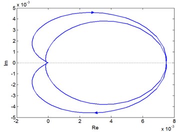
Similarly, it be seen from the phase diagram shown in Fig. 6(a) that the phase track line of XP type single-loop gear train circles (0, 0) point clockwise, but does not encircle (–1, 0j) point. Therefore, it is judged from the phase diagram that the XP type single-loop gear train is stable under the current conditions.
Fig. 5The amplitude-phase-frequency characteristic of single-loop gear system of XP type
a) Nyquist
b) Nichols
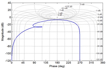
Likewise, it can be seen from the amplitude and phase characteristic diagram in Fig. 6(b) that, the amplitude margin and phase frequency margin of XP type single-loop gear system state are both infinite. Therefore, the system is stable under current conditions.
Fig. 6The amplitude-phase-frequency characteristic of single-loop gear system of XP type
a) Nyquist
b) Nichols
4.3.2. Dynamic characteristics from input to X system in a single loop
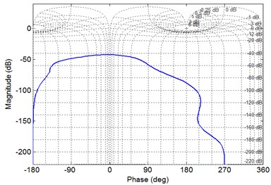
The system shown in Fig. 7(a) is a subsystem of the XP type single-loop gear system. The subsystem cuts off from the input end to the x-type element body to study the stable state of this type of subsystem in the single-loop system. By using the above analysis method, it is concluded that the dynamic characteristic state of the subsystem is stable.
Correspondingly, the amplitude margin 7.05 dB > 0 of the subsystem is concluded from the amplitude and phase characteristic diagram shown in Fig. 7(b). Combined with the above figure, the subsystem has no poles on the right side of the complex plane. Therefore, it can be judged that the subsystem is also stable.
Fig. 7The amplitude-phase-frequency characteristic of single-loop gear system of XP type
a) Nyquist
b) Nichols
4.3.3. Dynamic characteristics from input to P system in a single loop
The phase diagram shown in Fig. 8 is also a subsystem of the XP type single-loop gear system. The subsystem cuts off from the input end to the P-type element body to study the stable state of p-type element subsystem inside the single-loop system. Similarly, by using the same method, it is concluded that the P-type cell subsystem is also stable inside the single-loop system. Therefore, it is concluded from the above analysis that when the whole system is stable, the subsystems in the system are also stable.
Fig. 8The amplitude-phase-frequency characteristic of single-loop gear system of XP type
a) Nyquist
b) Nichols
5. Conclusions
In this research, study on dynamic characteristic of XP type single-loop gear system based on bond graph method. Simulation has been conducted to prove the efficiency of this method. The conclusions are listed as follows:
1) In accordance with the structural attributes of the gear transmission system, the P-type fixed-axis unit and x-type planetary unit modules are obtained. On this basis, the system structure diagram of XP type single-loop gear system is established.
2) The dynamics model of XP single-loop gear train is acquired by bond graph modeling method, and the dynamic state equation of single loop gear train is deduced.
3) The dynamic characteristics of XP single-loop gear train are received by numerical simulation, such as Nyquist diagram and Nichols diagram, which reflected the dynamic law of the system.
4) Through the weak nonlinear analysis of XP type single-loop gear system, it is concluded that the dynamic stability under the weak nonlinear state is better than that under the linear state.
References
-
S. Emmanuel, Y. Yihun, Z. Nili Ahmedabadi, and E. Boldsaikhan, “Planetary gear train microcrack detection using vibration data and convolutional neural networks,” Neural Computing and Applications, Vol. 33, No. 24, pp. 17223–17243, Dec. 2021, https://doi.org/10.1007/s00521-021-06314-x
-
Y. Guo, J. Keller, and W. Lacava, “Combined effects of gravity, bending moment, bearing clearance, and input torque on wind turbine planetary gear load sharing: preprint,” in American Gear Manufacturers Association Fall Technical Meeting, pp. 1–19, May 2016.
-
M. Sang, K. Huang, Y. Xiong, G. Han, and Z. Cheng, “Dynamic modeling and vibration analysis of a cracked 3K-II planetary gear set for fault detection,” Mechanical Sciences, Vol. 12, No. 2, pp. 847–861, Sep. 2021, https://doi.org/10.5194/ms-12-847-2021
-
F. Ren et al., “Investigation of dynamic load sharing behavior for herringbone planetary gears considering multicoupling manufacturing errors,” Shock and Vibration, Vol. 2021, pp. 1–15, Jul. 2021, https://doi.org/10.1155/2021/5511817
-
W. Wang et al., “A multi-objective power flow optimization control strategy for a power split plug-in hybrid electric vehicle using game theory,” Science China Technological Sciences, Vol. 64, No. 12, pp. 2718–2728, Dec. 2021, https://doi.org/10.1007/s11431-020-1770-3
-
Y. Cui, J. Gao, X. Ji, X. Zhou, and H. Yan, “The multi-attribute topological graph method and its application on power flow analysis in closed planetary gear trains,” Advances in Mechanical Engineering, Vol. 10, No. 8, p. 168781401879410, Aug. 2018, https://doi.org/10.1177/1687814018794103
-
E. L. Esmail, E. Pennestrì, and M. Cirelli, “Power-flow and mechanical efficiency computation in two-degrees-of-freedom planetary gear units: new compact formulas,” Applied Sciences, Vol. 11, No. 13, p. 5991, Jun. 2021, https://doi.org/10.3390/app11135991
-
H. Dong, H. Q. Zhang, X. L. Zhao, and L. L. Duan, “Study on dynamic load-sharing characteristics of face gear dual-power split transmission system with backlash, support and spline clearance,” Mechanical Sciences, Vol. 12, No. 1, pp. 573–587, May 2021, https://doi.org/10.5194/ms-12-573-2021
-
X. Zhou, Y. Cui, L. Li, L. Wang, X. Liu, and B. Zhang, “Signal de-noising in gear pitting fault identification by an improved singular value decomposition method,” Forschung im Ingenieurwesen, Vol. 84, No. 2, pp. 79–90, Jun. 2020, https://doi.org/10.1007/s10010-020-00400-7
-
Theissen J., Jayaram V., and Diekhans G., “The influence of backlash on the dynamic load of the gear transmission under cyclic loading,” Gear, Vol. 9, No. 2, pp. 53–56, 1985.
-
P. Zech, D. F. Plöger, and S. Rinderknecht, “Active control of planetary gearbox vibration using phase-exact and narrowband simultaneous equations adaptation without explicitly identified secondary path models,” Mechanical Systems and Signal Processing, Vol. 120, pp. 234–251, Apr. 2019, https://doi.org/10.1016/j.ymssp.2018.10.030
-
Y. Guo and R. G. Parker, “Dynamic analysis of planetary gears with bearing clearance,” Journal of Computational and Nonlinear Dynamics, Vol. 7, No. 4, pp. 1–15, Oct. 2012, https://doi.org/10.1115/1.4005929
-
J. Han, Y. Liu, L. Liang, Y. Zhao, and H. Zhang, “Dynamic analysis of a fault planetary gear system under nonlinear parameter excitation,” Shock and Vibration, Vol. 2021, pp. 1–17, Jul. 2021, https://doi.org/10.1155/2021/1787525
-
Lang Sherman Y. T., “Graph-theoretic modelling of epicyclic gear systems,” Mechanism and Machine Theory, Vol. 40, No. 5, pp. 511–529, May 2005, https://doi.org/10.1016/j.mechmachtheory.2004.12.001
-
Johnson R. and Towfigh K., “Great design of epicyclic gear trains using number synthesis,” Journal of Engineering for Industry, pp. 309–314, 1967.
-
R. Sanchez and A. Medina, “Wind turbine model simulation: A bond graph approach,” Simulation Modelling Practice and Theory, Vol. 41, No. 41, pp. 28–45, Feb. 2014, https://doi.org/10.1016/j.simpat.2013.11.001
-
Z. Khaouch, M. Zekraoui, J. Bengourram, N. Kouider, and M. Mabrouki, “Mechatronic modeling of a 750 kW fixed-speed wind energy conversion system using the bond graph approach,” ISA Transactions, Vol. 65, pp. 418–436, Nov. 2016, https://doi.org/10.1016/j.isatra.2016.07.009
-
Zhou X. T. et al., “Signal flow graph analysis method for kinematic characteristics of single degree of freedom planetary gear train,” Journal of Mechanical Strength, Vol. 40, No. 5, pp. 1143–1149, 2018.
-
Zhou X. T. et al., “Research of the transmission characteristic of planetary gear train based on the signal flow graph method,” Journal of Mechanical Transmission, Vol. 42, No. 1, pp. 17–21, 2018.
-
Zhao J. et al., “Integrated model control of brake-wheel system using bond graph method,” Advances in Mechanical Engineering, Vol. 10, No. 7, pp. 1–16, 2018.
-
X. Li and A. Wang, “A modularization method of dynamic system modeling for multiple planetary gear trains transmission gearbox,” Mechanism and Machine Theory, Vol. 136, pp. 162–177, Jun. 2019, https://doi.org/10.1016/j.mechmachtheory.2019.03.002
-
J. Rodríguez-Guillén, R. Salas-Cabrera, and P. M. García-Vite, “Bond Graph as a formal methodology for obtaining a wind turbine drive train model in the per-unit system,” International Journal of Electrical Power and Energy Systems, Vol. 124, p. 106382, Jan. 2021, https://doi.org/10.1016/j.ijepes.2020.106382
-
Z. Jahanbin, A. Selk Ghafari, A. Ebrahimi, and A. Meghdari, “Multi-body simulation of a flapping-wing robot using an efficient dynamical model,” Journal of the Brazilian Society of Mechanical Sciences and Engineering, Vol. 38, No. 1, pp. 133–149, Jan. 2016, https://doi.org/10.1007/s40430-015-0350-4
-
Y. S. Hamed, K. M. Albogamy, and M. Sayed, “Nonlinear vibrations control of a contact-mode AFM model via a time-delayed positive position feedback,” Alexandria Engineering Journal, Vol. 60, No. 1, pp. 963–977, Feb. 2021, https://doi.org/10.1016/j.aej.2020.10.024
-
M. Sayed, A. A. Mousa, and I. Mustafa, “Stability and bifurcation analysis of a buckled beam via active control,” Applied Mathematical Modelling, Vol. 82, pp. 649–665, Jun. 2020, https://doi.org/10.1016/j.apm.2020.01.074
-
Y. S. Hamed, A. El Shehry, and M. Sayed, “Nonlinear modified positive position feedback control of cantilever beam system carrying an intermediate lumped mass,” Alexandria Engineering Journal, Vol. 59, No. 5, pp. 3847–3862, Oct. 2020.
-
Y. S. Hamed, K. M. Albogamy, and M. Sayed, “A proportional derivative (PD) controller for suppression the vibrations of a contact-mode AFM model,” IEEE Access, Vol. 8, pp. 214061–214070, 2020, https://doi.org/10.1109/access.2020.3038150
-
Cui Y. H., “Study on the bifurcated power planetary transmission,” Xi’an University of Technology, Xi’an, 1998.
-
Ma Y. L. and Zhang Y. Z., “Kinematic characteristic state models for basic units of compound gear train,” China Mechanical Engineering, Vol. 25, No. 15, pp. 1999–2003, 2014.
About this article

This work was supported by grants from the Scientific Research Program Funded by Shaanxi Provincial Education Department of China (No. 21JK0503) and Introduce High-level Talents to Start Scientific Research Funds by Shaanxi Polytechnic Institute of China (No. 2020-9), which were highly appreciated by the authors.
