Abstract
This study aims to develop and evaluate an innovative design of a shell and tube heat exchanger (STHX) featuring porous sectional baffles to enhance its thermal and hydraulic performance (TPF). A numerical investigation based on computational fluid dynamics (CFD) is conducted to analyze the TPF of STHX. A parametric study is performed to evaluate the effects of baffle inclination angle and double cut ratio design on heat transfer and pressure drop characteristics. The model included six metal foam baffles with an initial cut ratio of 20 % (MFBs), and its performance was compared to that of a conventional heat exchanger with solid baffles. The effect of foam baffle inclinations at various angles (0°,10°, 20°, 30° and 30° parallel) was also analysed. Also, the effect of the double-cut ratio of the foam baffle (2×10 %, 2×15 %, 2×20 %, and 2×10 % parallel) over a range of mass flow rates between 1.2 and 2.0 kg/s and range (11000-16000). The results showed that the use of MFBs lead to a maximum reduction of by 32 % with (2×10 %) design at 2 kg/s accompanied by a significant improvement in TPF. Furthermore, a 30° baffle inclination improved the TPF to 2.207 at (1.2 kg/s), accompanied by a 50 % increase in and a 25.5 % reduction . The best TPF was recorded at the ratio (2×10 %), where the (TPF) = 2.389 at 1.2 kg/s, with a improvement of 54.4 % compared to a solid baffle. The obtained results provide useful design guidelines for STHXs widely used in energy, petrochemical, and chemical processing industries.
1. Introduction
The STHX is a popular type of heat exchangers in various industrial fields, particularly in marine and hydraulic applications, accounting for approximately 35-40 % of all heat exchangers used in the chemical industry [1]. This type is very popular because it has a strong mechanical structure [2], is less costly to maintain, is easier to engineer, and transfers heat more efficiently due to its cross-flow properties [3]-[4]. The shell and tube heat exchanger (STHX) is one of the most widely used types of heat exchangers
Metal foams are promising materials for enhancing heat transfer due to their unique properties, which combine high thermal conductivity with outstanding permeability. Studies have shown that aluminum and copper foams exhibit reliable performance when employed in various types of heat exchangers, without significant problems related to clogging or damage from particles or debris [5]. Alhusseny et al. [6] conducted a study to enhance the performance of two-pipe heat exchangers by utilising a composite technology that combines rotating metal foam with a porous layer. The results indicated that the metal foam increased the thermal efficiency compared to conventional designs, with the highest density foam (30 PPI) achieving the best performance. The composite design also helped reduce pumping energy, recording a thermal improvement of between 200 % and 300 % at a rotation speed of 500 rpm.
An innovative design for a STHX equipped with segmental porous foam baffles was presented by Abbasi et al. [7] to improve thermal and hydraulic performance. Numerical modeling (CFD) and artificial intelligence algorithms (ANN and MOGA) were employed to investigate the impact of baffle number, cross-section angle, and baffle thickness on exchanger performance. The results showed that increasing the baffle number enhances heat transfer but increases pressure drop. In contrast, the baffle angle is the most important factor in achieving a balance between thermal efficiency and hydraulic resistance. The optimal design was achieved with ten baffles at an angle of 111.9° and a thickness of 16.69 mm, resulting in an 11.15 % thermal improvement and a 61.3 % reduction in pressure loss compared to the conventional design. Dongellini et al. [8] assessed the thermal and hydraulic performances of an air-water heat exchanger constructed from high-porosity aluminum foam (> 96 %, 10 PPI) and contrasted it with a traditional finned exchanger. Prototypes were tested inside a commercial air conditioning unit, examining different methods of bonding the foam to the copper tubes, including compression fitting, thermal grease, and epoxy bonding. The results showed that epoxy bonding provided the best thermal performance, with a 110 % increase, while maintaining a good balance in hydraulic performance, despite a 13-42 % higher pressure loss compared to finned exchangers. Chen et al. [9] evaluated the thermal and hydraulic performance of a shell-and-tube heat exchanger using copper foam baffles. Their findings were compared with conventional designs employing either baffle-free or solid-baffle configurations. Six porous baffles with pore densities ranging from 5 to 40 PPI were used. The finding showed that the foam baffles significantly enhanced flow turbulence and heat transfer, with optimal thermal performance attained at a density of 40 PPI. Furthermore, the foam baffles displayed reduced pressure losses relative to conventional metal baffles, indicating enhanced thermal and hydraulic efficiency. Hossein et al .[10] presented a numerical study to evaluate the performance of shell and tube heat exchangers (STHX) when fully or partially filled with a porous metal foam compared to a conventional design. CFD simulations demonstrated that the porous foam enhanced the uniformity of heat distribution and increased thermal efficiency by up to 60 %, accompanied by a corresponding increase in pressure loss. Partial foam filling diminished pressure loss to approximately fifty percent of the full filling value, rendering it a viable solution that harmonises thermal efficiency and flow resistance. Yang et al. [11] developed a shell-and-tube thermal energy storage unit filled with open-cell copper foam and finned to enhance the performance of a phase change material (PCM). A numerical simulation (CFD) was used to analyse the heat exchange between the foam and the material. The results showed that the composite-finned (FMFT) design reduced the melting time by 85.83 % and the solidification time by 95.83 % and increased the heat transfer rate by 1835 % compared to a smooth tube. Kiwan et al. [12] conducted an experimental study on a vertically positioned cylinder subjected to a constant heat flux and fitted with porous aluminum fins. The study examined fin diameters of 50, 60, and 80 mm, fin numbers ranging from 1 to 5, and fin thicknesses between 10 and 20 mm to evaluate their influence on the thermal performance. The results indicated that the higher-permeability fins improved heat transfer by 131.8 % for a filled 50 mm diameter cylinder compared to a finless cylinder. Rabeeah et al. [13]-[14] examined the performance of double-pipe heat exchangers (DPHX) using open-cell copper foam baffles through numerical and experimental approaches. The results showed that adding foam improved heat transfer by 32-45 % and raised the Nusselt number by 117-146 % compared to a conventional exchanger, with a limited increase in pressure loss. Additionally, it was demonstrated that a 180° baffle angle and a pore density of 40 PPI achieved the best thermal performance. In contrast, a 10 mm partial fill achieved an optimal balance between thermal efficiency and hydraulic resistance, making this design suitable for recovering heat energy. Jubear et al. [15] investigated the performance improvement of a double pipe heat exchanger (DPHX) using copper foam filled with a nanofluid (Al2O3-water). The ANSYS Fluent simulation showed that this combination raised the Nusselt number by 92 % and the thermal conductivity by 1.9 times, with minimal pressure loss (< 10 %). The Performance Evaluation Criterion (PEC) was 1.82 at a nanofluid concentration of 2 %, confirming the effectiveness of this design in enhancing the efficiency of heat exchangers for renewable energy applications.
A numerical study of the influence of porous masses on heat transfer and fluid flow inside a three dimensional cylindrical heat exchanger was conducted by Rong et al. [16] using the lattice Boltzmann method (LBM). The results showed that the Nusselt number () increased with increasing the height of the masses and decreased with increasing their width or spacing, which reduced heat mixing. It was also shown that a lower Darcy number (), i.e., lower permeability, enhanced heat transfer by increasing the flow velocity near the wall, while the effect of porosity () was limited compared to other factors. Naqvi and Wang [17] investigated the improvement of a shell and tube heat exchanger (STHX) performance by integrating anti-vibration baffles with porous media, such as metal foam, to enhance heat transfer and reduce pressure loss. ANSYS Fluent simulations indicated that this combination enhanced the heat transfer coefficient by 1.7 times, attaining optimal thermal and hydraulic equilibrium at a porosity of 0.6, especially when the foam was affixed to the inner wall of the tubes. Hu et al. [18] conducted an experimental study to evaluate the heat transfer performance and pressure drop characteristics of humid air passing through copper foam coated with a hydrophobic layer under dehumidification conditions. Their findings indicated that the hydrophobic coating improved the heat-transfer coefficient by 5-34 % at low relative humidity levels (30-50 %) for foam with a pore density of 20 PPI. At rising humidity levels, the coating significantly increased pressure loss by up to 95 % due to increased flow resistance within the foam's pore structure. Yang et al. [19] investigated experimentally an air-water heat exchanger made of high-porosity aluminum foam (> 96 %, 10 PPI) and compared it with finned exchangers. The results showed that the epoxy bonding between the foam and copper tubes improved heat transfer by 110 % and achieved the best thermal and hydraulic balance, despite a 13-42 % increase in pressure loss compared to the conventional design.
Although several previous studies have demonstrated a significant improvement in heat transfer when using metal foam within heat exchangers, this improvement has often been accompanied by a substantial increase in pressure drop due to the high flow resistance within the porous structure. This behavior reflects the well-known trade-off between enhanced heat transfer and hydraulic penalty, which remains a design challenge in heat exchanger applications. This study contributes to the field of mathematical modeling and numerical simulation in thermal engineering by developing a CFD-based model to evaluate the performance of metal foam baffles in STHXs. Since metal foam represents a porous medium with complex solid-liquid phase thermal interactions, a local thermal inequilibrium (LTNE) model was adopted to describe the heat transfer between the two phases. Momentum transfer within the porous medium was modeled using the Brinkman-Forchheimer-Darcy formula, which considers the effects of viscosity and inertial flow within the porous structure.
Based on this, this study aims to develop alternative geometric configurations for foam baffles that enable an improved balance between thermal performance and pressure drop. This is achieved by first, presenting a systematic analysis of the effect of inclination angles (0°, 10°, 20°, 30°, and 30° parallel) on thermal and hydraulic performance at various flow rates (1.2-2 kg/s). Second, a design for a double-cut foam baffle (2×10 %, 2×15 %, 2×20 %) in counter arrangement and 2×10 % in a parallel arrangement (2×10 %) was developed to evaluate the effect of geometrically redistributing porosity on overall performance.
2. Numerical simulation
Numerical analysis was conducted on the basis of the finite volume technique (FVM) in ANSYS Fluent 2025 R2 to obtain the solution of governing equations. The SIMPLE algorithm was used for pressure-velocity coupling, while second-order upwind discretisation schemes were employed to enhance the accuracy of numerical spatial gradients. The turbulent flow inside the shell-and-tube heat exchanger was modeled using the standard - turbulence model. Convergence limits of 10-4, 10-4, 10-7, and 10-4 were established for the continuity, momentum, energy, and turbulence equations, respectively. However, to guarantee numerical stability and expedite solution convergence, relaxation factors were set at 0.3 for pressure, 0.7 for momentum, and 1.0 for energy.
2.1. Model description
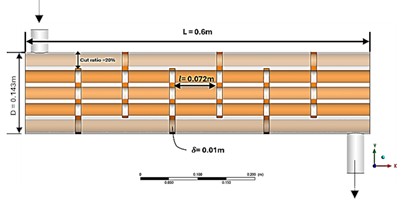
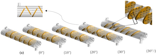
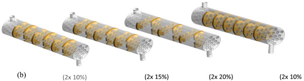
This study adopted the STHX geometric configuration developed by Nie et al. [20], which was also used for numerical verification. The numerical model consists of a shell with an inner diameter of 143 mm and a total length of 600 mm, containing thirteen tubes with an outer diameter of 22 mm arranged in a 60° triangular layout. improve thermal and hydraulic performance, the heat exchanger was equipped with copper metal foam baffles, featuring a porosity of 0.9 and a pore density of 40 PPI, and was compared with conventional solid baffles. The effect of foam baffle inclinations at various angles, including 0°, 10°, 20°, and 30° for opposite inclinations, as well as a 30° inclination in parallel, was analysed. The effect of double cut ratios (2× BCs) was also studied under four design cases: (2×10 %), (2×15 %), (2×20 %) opposite baffle direction, and (2×10 %) parallel baffle direction, which were distributed evenly within the shell as shown in Fig. 1. The system performance was evaluated at various mass flow rates of 1.2, 1.4, 1.6, 1.8, and 2.0 kg/s, while the thermophysical properties of the materials used are presented in Table 1. Forty-five (45) numerical simulations were performed to optimise the equilibrium between thermal performance and hydraulic flow efficiency, hence enhancing heat transfer while minimising pressure drop.
Table 1The thermophysical properties of materials [20, 21, 22]
Physical properties | Water | Copper | Steel |
Density (kg/m3) | 998.2 | 8978 | 8030 |
Thermal conductivity (W/m. k) | 0.6 | 387.6 | 16.27 |
Specific heat (J/kg. k) | 4182 | 381 | 502.48 |
Dynamic viscosity (kg/m. s) | 0.001 | – | – |
Fig. 1Geometry of physical model with two configurations of baffles: a) various angle inclination b) 2x Bcs %
2.2. Mathematical assumptions
To simplify the calculations and ensure the stability of the numerical solution, the following assumptions were adopted:
1) Leakage between the shell and the baffles and between the baffles and the tubes is neglected.
2) The flow in the shell is considered turbulent, while the flow inside the metal foam is considered locally laminar due to the low velocity and high flow resistance.
3) Application of the local thermal nonequilibrium (LTNE) model between the water and the metal foam, assuming the foam is isotropic and homogeneous.
4) The thermophysical properties of the water and foam are considered constant and independent of temperature within the operating range.
2.3. Model limitations
The numerical model in this study assumes a perfect seal between the baffles and the shell, neglecting the effects of clearance gaps and associated lateral flow. This simplification aims to isolate the thermal-hydraulic influence of foam baffle designs under ideal engineering conditions, ensuring a controlled relative comparison between the studied cases. However, this assumption may lead to a potential overestimation of the absolute thermal performance compared to real-world systems where lateral leakage occurs around the baffles. Therefore, the absolute values of the TPF can be considered a theoretical upper limit of performance, while the relative differences between the various designs remain analytically significant since the same assumptions are applied to all cases.
2.4. Governing equation
Governing equations are used to analyze the flow associated with heat transfer within a heat exchanger. The water flow field in the fluid zone is described by the Navier-Stokes equations, while the flow field within the homogeneous, isotropic porous medium is represented by the momentum equation derived from the extended Brinkman-Forchheimer-Darcy model. Governing equations include:
Mass conservation (continuity equation). It states the constancy of mass in any closed system over time, in accordance with the principle of mass conservation [23]:
Momentum equations. The rate of change of momentum is equal to the net force acting on the body according to the Navier-Stokes equations and Newton’s second law of motion [24].
-axis:
-axis:
-axis:
The governing momentum equations are expressed in dimensionless form using the Brinkman-Forchheimer-Darcy model. The dimensionless parameters include the Reynolds number (), Darcy number (), and Forchheimer coefficient (), which represent inertial, viscous, and porous resistance effects, respectively.
Energy Equations. The fluid energy equation in a porous medium (LTNE) is:
where denotes the effective thermal conductivity of the fluid phase.
Energy equation of the solid matrix (LTNE) is:
The energy equation for an incompressible fluid can be represented as a heat equation describing the static temperature, in the absence of foam as:
2.5. Mesh independence study
The geometric model was generated using the Fluent Meshing tool based on tetrahedral cells, as illustrated in Fig. 2. To more accurately represent the steep temperature and velocity gradients near the tube walls, fine mesh layers were added around the surfaces to adequately characterize the boundary region. Eight meshes of different element number were tested, with 2,667,524, 3,100,218, 3,470,912, 3,980,437, 4,160,300, 4,420,994 4,681,688 and 4,942,382 elements, for (STHX) equipped with six copper foam baffles with a double cut ratio 2×10 % at a mass flow rate of 1.2 kg/s to assess their influence on the model accuracy. The results, as shown in Table 2, show that the change in pressure drop and outlet fluid temperature becomes minimal as the number of elements increases. The relative errors for the 3,980,437 and 4,160,300 element meshes were approximately 0.03 % for the pressure drop and 0.01 % for outlet temperature. Accordingly, the 3,980,437-element mesh was adopted, as it achieves an ideal balance between numerical representation accuracy and reduced computational time.
Fig. 2STHX grid system with inclined foam baffles and double-cut baffles
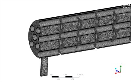
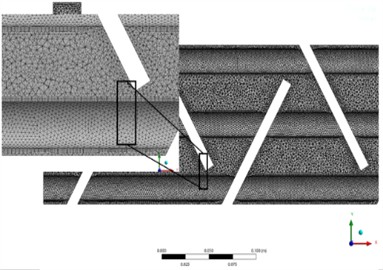
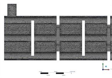
Table 2The mesh independence on outlet water temperature and pressure drop for (2×10 %)
No. of mesh elements | Outlet temperature | Percentage deviation | Pressure drops | Percentage deviation |
2,667,524 | 310.00 | – | 7000 | – |
2,850,533 | 310.45 | 1.93 | 7078 | 1.10 |
3,100,218 | 310.85 | 0.13 | 7100 | 0.31 |
3,330,455 | 311.00 | 0.05 | 7112 | 0.17 |
3,470,912 | 311.12 | 0.039 | 7120 | 0.11 |
3,980,437 | 311.20 | 0.025 | 7126 | 0.084 |
4,160,300 | 311.23 | 0.010 | 7128 | 0.028 |
4,420,994 | 311.26 | 0.0096 | 7130 | 0.028 |
4,681,688 | 311.28 | 0.0064 | 7131 | 0.014 |
2.6. Boundary conditions
The local thermal nonequilibrium (LTNE) model was used to represent the thermal interaction between the water and the solid metallic foam structure, while the momentum behavior inside the porous medium was described using the extended Brinkman-Forchheimer-Darcy model [25]. Based on this model, the flow coefficients expressed as viscous resistance, inertial loss coefficient (), and the interfacial area () were derived:
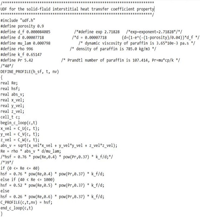
The interfacial heat transfer coefficient () was determined using a User-Defined Function (UDF) that depends on the fluid velocity, as per the instructions provided in the ANSYS Fluent User’s Manual [26].
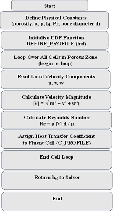
In the present study, the porous metal foam region is modeled using the (LTNE) approach, where separate energy equations are solved for the fluid and solid phases. The UDF dynamically updates the () based on the local flow conditions, particularly the instantaneous fluid velocity within each computational cell of the porous region. The function was compiled in C++ and integrated into the solution environment using the Compiled UDF mechanism to ensure numerical stability and accurate physical representation. The numerical procedure adopted in the present study is illustrated in Fig. 3. In addition, the core implementation of the UDF used to evaluate the interfacial heat transfer coefficient is provided in Fig. 4.
Fig. 3Flowchart of the (UDF) for calculating the fluid-solid interfacial heat transfer coefficient in metal foam porous media
The interface area of the metal foam is calculated based on the following mathematical relationship:
In the previous equations, the symbol () denotes porosity, while () and () represent fiber diameter and pore size of the metallic foam, respectively: viscous resistance = , inertial resistance = .
Fig. 4Implementation of the UDF for interfacial heat transfer coefficient
The heat transfer coefficient at the interface () between water and metal foam was calculated based on the experimental formulas proposed in the Zukauskas model [27]:
The tube walls are treated as uniform heat transfer boundaries, while zero velocities are assumed at the wall surface under the non-slip condition: , 325 K.
The shell surface is treated as adiabatic boundary, were , and the normal temperature gradient is zero = 0.
The pressure outlet boundary is represented by the water outlet surface represents, were , and ( 0).
The initial conditions for the computational domain were set such that the velocities were 0 and the temperature was 300 K.
The letters , , and refer to the velocity components along the , , and axes, respectively.
The limit conditions were chosen to ensure realistic physical representation and numerical stability of the solution. A constant mass flow condition at the inlet was adopted to precisely control the Reynolds number and ensure comparability between cases, while a constant pressure condition at the outlet was imposed to simulate free flow and minimize the possibility of numerical backflow. A non-slip condition on the walls was imposed to represent the actual behavior of viscous fluids, and the inlet temperature was fixed at 300 K to represent a reference case for cold water flow. Zero initial velocities were used to ensure that the solution started from a numerically stable state without non-physical initial effects.
3. Data processing
The heat transfer coefficient is calculated using equation [21]:
The Nusselt number () is defined by the following expression [28]:
The hydraulic diameter on the side of shell is defined as follows [28]:
The thermal Performance factor (TPF) is used as a comprehensive indicator to evaluate the efficiency of shell and tube heat exchangers (STHX) from both the thermal and hydraulic perspectives [29]:
In this study, the TPF is normalized with respect to the baseline case of the conventional solid-baffle heat exchanger. This normalization allows a direct comparison between the enhanced configuration with metal foam baffles and the reference configuration.
Where and represent the Nusselt numbers for the foam-baffled and solid-baffled exchangers, respectively. The inlet and outlet temperatures of the fluid on the shell side are designated as Tin and Tout, respectively, while Tw refers to the temperature of the tube wall. do denotes the outer diameter of the tube, while pt represents the tube pitch. The symbols refer to the pressure drop associated with the foam-baffled and conventional heat exchangers, respectively. The mass flow rate is denoted by ṁ, and the specific heat capacity is denoted by .
4. Results and discussion
4.1. Validation of simulation
The procedure of numerical simulation is firstly validation for an STHX based on a previous published study conducted by Nie et al. [20] using ANSYS 2025 R2. This validation step is necessary for securing the reliability of the numerical analysis before commencing the investigation of the targeted 3D geometry in the current study. The validation process was based on the survey by. Specifically, the model was evaluated by comparing the predicted pressure drop and heat transfer coefficient on the shell side under counter-flow conditions at mass flow rates of 0.5, 1.0, 1.5, and 2.0 kg/s. The numerical predictions were very close to the reference data, with an average accuracy of 95.25 % for the pressure drop and 97.2 % for the heat transfer coefficient. The validation results are illustrated in Fig. 5, affirming the model's appropriateness for future simulations of metal-foam-integrated combinations.
Fig. 5Validation of Nie et al. [20]
![Validation of Nie et al. [20]](https://static-01.extrica.com/articles/26048/26048-img9.jpg)
![Validation of Nie et al. [20]](https://static-01.extrica.com/articles/26048/26048-img10.jpg)
To further verify the reliability of the numerical model in the metal foam region, the simulation was compared with the published data reported by Nie et al. The comparison was performed for similar operating conditions and foam properties (40,80,120,160 and 200 PPI). The predicted outlet temperature and pressure drop showed good agreement with the published results, with an average accuracy of 96.64 % for outlet temperature and 95.4 % for the pressure drop as shown in Fig. 6. This confirms the validity of the porous media model used to represent the metal foam structure.
Fig. 6Metal foam validation of Nie et al. [20]
![Metal foam validation of Nie et al. [20]](https://static-01.extrica.com/articles/26048/26048-img11.jpg)
![Metal foam validation of Nie et al. [20]](https://static-01.extrica.com/articles/26048/26048-img12.jpg)
4.2. Numerical results
Given the possibility of modifying the geometric properties of foam baffles, such as shape, inclination angle, cut ratios, thickness, porosity, and density, a numerical work was implemented to examine these parameters influence on the STHX’s behavior. The research precisely assessed the influence of chosen parameters on the thermal and hydrodynamic performance of the heat exchanger at five distinct flow rates. The analysis encompassed the outlet fluid temperature (), Nusselt number (), and pressure drop (), enabling the identification of the optimal baffle configuration to achieve the best balance between enhanced heat transfer and reduced hydraulic losses.
4.2.1. The effect of inclination of baffle
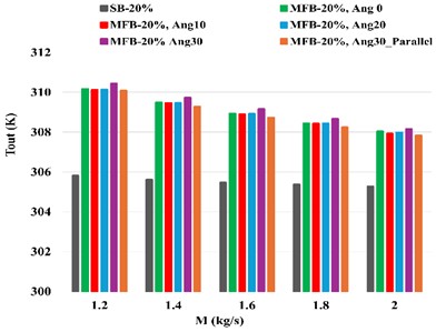
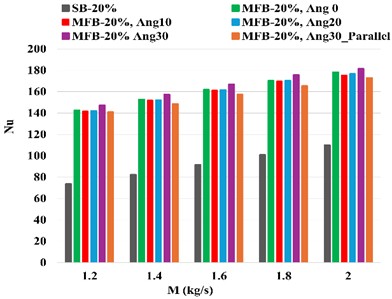
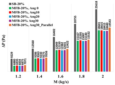
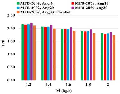
This section analyzes the thermal and hydraulic performance of an STHX fitted with foam and solid baffles of varying angle inclination, while maintaining constant thickness (10 mm), pore density (40 PPI), porosity (0.9), and number of baffles (6). Fig. 6 shows the , , , and TPF for both conditions.
The Fig. 7(a) illustrates the effect of the baffle inclination angle and arrangement pattern on the outlet temperature at a 20 % cut ratio. At a mass flow rate of 1.2 kg/s and 0° inclination angle the outlet temperature increased to 310.17 K compared to 305.82 K when using solid baffles. Increasing the angle of inclination also enhanced turbulence and lengthened the heat exchange path, leading to the formation of secondary eddies that further regenerated the thermal boundary layer on the pipe surfaces, thus enhancing forced convection heat transfer. This resulted in a 43.4 % increase in the inlet-out temperature difference at an angle of 30° in the non-parallel arrangement and 42.6 % in the parallel arrangement compared to solid baffles. The superiority of the non-parallel arrangement is explained by the formation of opposing vortices that lead to continuous fluid redistribution within the cross-section and break the rotational structure, thus promoting more effective boundary layer regeneration. The parallel arrangement produces a semi-regular helical rotation pattern that provides stable but less intense mixing than the opposing pattern. Furthermore, the Tout decreased gradually with increasing mass flow rate due to the shorter fluid residence time within the heat exchange zone.
Fig. 7(b) showed that a metal baffle inclination of 30° achieves the highest Nusselt number values [30], with an improvement of approximately 50 % compared to solid baffles. This is attributed to the generation of a strong spiral flow within the casing due to the fluid’s deflection from the axial path. This leads to the formation of secondary vortices that continuously replenish the thermal boundary layer, thus enhancing forced convection heat transfer. Furthermore, the higher mass flow rate leads to an increased Nusselt number () due to the higher flow velocity and Reynolds number, which reduces the thickness of the thermal insulation layer and enhances convection.
The Fig. 7(c) shows that the pressure drops () change positively with the growth of mass flow rate due to the increased flow velocity and greater frictional losses within the shell. Solid baffles exhibit the highest values as a result to the abrupt change in flow direction, while the porosity of foam baffles mitigates hydraulic losses by providing alternative flow paths. The results indicate that a 20° angle achieves the best reduction of approximately 26 % compared to the solid baffle, as this moderate slope reduces the formation of strong eddies and backflow recirculation. The non-parallel 30° configuration, the improvement is 25.5 %, as the opposing vortices enhance shear and partially increase frictional loss. Conversely, parallel inclination at (30°) results in a relatively smaller reduction of 23.3 % due to the increased effective flow path length, which causes a slight increase in friction and a limited rise in [30], although it remains lower than the solid baffle due to the permeability of the foam.
Fig. 7(d) illustrates that the TPF decreases gradually with the growth of the mass flow rate. This reduction is caused by the rapid pressure drop in a greater rate than the heat transfer improvement does at high speeds. A 30° angle exhibits the highest TPF value of 2.207, demonstrating its ability to enhance secondary flow and regenerate the boundary layer with minimal increase in hydraulic resistance. Conversely, the parallel inclination at 30°, the lowest TPF value of 2.095, resulting from the lengthening of the effective path and the accumulation of frictional losses within the porous medium. Angles of 0° and 20° exhibit moderate performance due to a constrained equilibrium between thermal turbulence and elevated pressure drop.
Fig. 7a) Outlet water temperature, b) Nu, c) pressure, d) TPF of STHX at different inclinations (foam baffles at N= 6 and S= 10 mm PPI = 40
a)
b)
c)
d)
4.2.2. The effect of double cut ratios for baffle (2×Bcs)
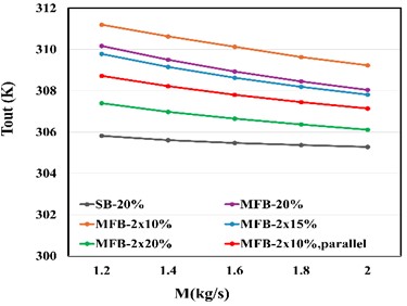
This section of the study elucidates the inquiry about the impact of double cut ratios for baffles on the performance of STHX. Fig. 8(a) shows that the double cut ratio (2×10 %) achieves the highest outlet temperature of 311.2 K at a flow rate of 1.2 kg/s, exceeding the conventional design with a 20 % cut ratio (MFB20 %). This performance is attributed to the smaller openings forcing a more intense flow redistribution within the foam structure, increasing local acceleration and shear intensity around the cut edges. This leads to frequent regeneration of the thermal boundary layer and enhanced cross-mixing.
In contrast, the parallel arrangement at (2×10 %) results in a more uniform flow pattern that reduces eddy current interaction, thus lowering the heat transfer efficiency. Increasing the cut ratio to (2×15 %) and then (2×20 %) widens the flow paths and increases the bypass flow, reducing redirection and internal mixing and lowering the effective residence time. This explains the lower outlet temperature of 307.4 K at (2×20 %). A general decrease in outlet temperature is also observed with an increase in mass flow rate as a result of the decreasing residence time within the heat exchange zone.
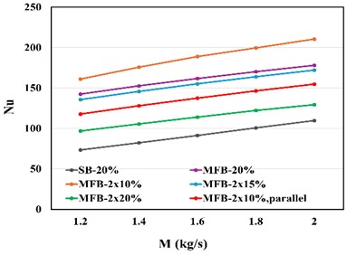
As illustrated in Fig. 8(b), Both and mass flow rate increases simultaneously due to enhanced turbulence and disruption of the boundary layer, thus improving convection efficiency. The peak value of 210.5 is recorded at a maximum flow rate of 2 kg/s, associated with a minimal double cut ratio of 2×10 %. This reduction is ascribed to constricted pathways and the formation of effective vortices, which improve thermal mixing and surpass the value of 178 for MFB 20 %. Higher double cut ratios (2×15 % and 2×20 %) result in progressively lower values of 172 and 129, respectively, due to increased bypass flow and reduced thermal interaction with the surfaces. Furthermore, the non-parallel configuration exhibits superior performance compared to the parallel arrangement, which is attributed to enhanced flow direction variability and optimised mixing within the shell.
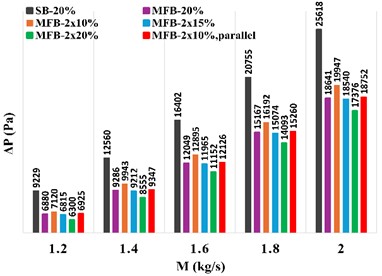
As illustrated in Fig. 8(c) the double cut ratio of 2×10 %, the passages are relatively smaller, increasing the local velocity within the openings and amplifying the contribution of the inertial term in the Brinkman-Forchheimer model. Consequently, values are higher compared to higher cut ratios. As the cut ratio increases to 2×20 %, the flow channels widen, increasing lateral flow. This leads to higher effective permeability and reduced local acceleration, resulting in a 31.7 % decrease in compared to solid baffles at 1.2 kg/s. In a parallel arrangement at 2×10 %, the regularity of the longitudinal channels reduces repeated directional deviations and limits local flow diversion losses, resulting in a slight additional 2.4 % reduction in compared to the non-parallel arrangement at the same cutoff ratio. Generally, increases with increasing mass flow rate due to the growing shear forces and the inertial contribution associated with a higher Reynolds number.
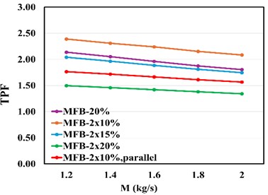
Fig. 8a) Outlet water temperature, b) Nu, c) Pressure drop, d) TPF of STHX at different mass flow rate with different double cut ratio (foam baffles at N= 6 and S= 10 mm PPI = 40
a)
b)
c)
d)
Building upon the previously discussed, the entire thermal-hydraulic performance can be further evaluated using the Thermal Performance Factor (TPF), which builds upon the previously stated trends in pressure drop and heat transfer enhancement. The TPF indicator provides a comprehensive view of the net benefit of foam-baffle designs at various mass flow rates. Fig. 8(d) shows the inverse relation between the gradual decrease of TPF and the mass flow rate increase for all cases. This relation is due to the rapid pressure drop increase in comparison with the thermal improvement change rate. The (2×10 %) exhibits the highest performance (2.389) and outperforms the MFB-20 % by approximately 10.5 % at 1.2 kg/s, due to increased turbulence and efficient boundary layer regeneration. Additionally, the foam-baffle design (2×15 %) exhibits stable thermal superiority with a TPF of 2.042. Conversely, the (2×20 %) exhibits the lowest TPF due to high Bypass flow and low residence time. The parallel configuration (2×10 %) also records a TPF approximately 26 % lower than the non-parallel configuration due to the regularity of the longitudinal path and weak secondary eddies.
4.3. Comparison of contours shapes
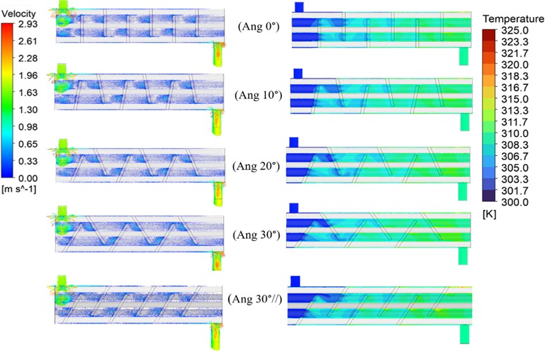
Fig. 9 illustrates the water velocity and temperature distribution using porous metal baffles with different inclination angles (0, 10°, 20°, 30°, and 30°) at a constant flow rate of 1.2 kg/s. The velocity vectors contours indicate that increasing the inclination angle to 30° enhances secondary flow and generates stronger eddies behind the baffles, resulting in boundary layer regeneration, reduced thickness, and enhanced convection. Conversely, a parallel inclination regulated the longitudinal flow and reduced transverse turbulence, thus limiting heat transfer. Fig. 10 demonstrates that using a small double cut ratio (2×10 %) generates strong secondary eddies between the tubes, enhances flow turbulence and regenerates the tube’s surfaces boundary layer. This behavior leads to enhanced thermal mixing and an increased thermal contact time between the fluid and the solid surface, which is reflected in a significant increase in the temperature of the outgoing water compared to other cases. As for the (2×10 % parallel) case, the parallel arrangement of baffles directs the flow in a nearly regular longitudinal manner. This arrangement limiting the formation of transverse eddies and resulting in weaker mixing and a decrease in heat transfer efficiency, despite a reduction in hydraulic resistance.
Fig. 9Velocity vectors and water temperature distributions at a mass flow rate of 1.2 kg/s for STHX equipped with foam baffles of varying angles of inclination
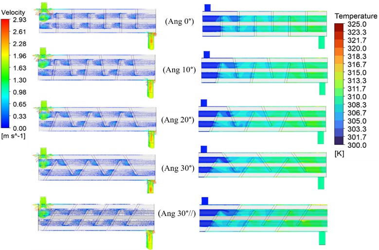
Fig. 10Velocity vectors and water temperature distributions at 1.2 kg/s for STHX equipped with foam baffles of different double cut ratio
5. Conclusions
An assessment of the thermal performance factor (TPF) of the STHX using metal foam barriers with diverse geometric characteristics was performed, juxtaposing it with traditional solid baffles. The results demonstrate that the foam baffles contribute to both enhanced heat transfer and reduced pressure drop, thereby increasing the operational efficiency of the heat exchanger. Accordingly, a number of main conclusions are drawn as in below:
1) Using foam baffles with different configurations significantly improved the outlet temperature. The 30° inclination and the (2×10 %) design increased the improvement in the temperature difference at 1.2 kg/s to 43.3 % and 47 %, respectively, compared to solid baffles.
2) By changing the angle of inclination, the Nusselt number () showed the highest improvement with a 30° angle of inclination, at 1.2 kg/s, by 50 %, thanks to increased turbulence. As for the double cut (2×10 %), it achieved an even greater improvement, surpassing the MFB20% with the same cut ratio by 15.4 % at a rate of 2 kg/s. Thus, the data confirms the effectiveness of the engineering modification in enhancing heat transfer efficiency.
3) The study found that a maximum pressure drop reduction of 32% was achieved under the parallel double-cut design (2×10 %), while reductions of 27 % and 25.5 % were observed at 0° inclination for mass flow rates of 2 kg/s and 1.2 kg/s, respectively. This reduction is attributed to the high permeability of the metal foam structure, which provides additional flow paths and reduces hydraulic resistance caused by abrupt changes in flow direction.
4) The investigation revealed that the angle of inclination had a limited effect on in comparison to zero inclination (MFB20%). However, a parallel inclination of 30° resulted in a marginal increase due to the regularity of the flow path. increases with increasing mass flow rate, while larger double-cut ratios reduce its value due to wider open paths; smaller ratios, on the other hand, maintain higher hydraulic resistance.
5) Among all the analysed situations, STHX heat exchangers with metal foam baffles demonstrated superior TPF compared to those with conventional solid baffles, especially at a 2×10 % double cutoff ratio and a mass flow rate of 1.2 kg/s. The TPF attained 2.389, accompanied by a pressure drop of approximately 23 % and an increase in the outlet fluid temperature to 311.2 K compared to 305 K in the solid baffle, thus validating the efficacy of this arrangement in enhancing heat transfer while reducing hydraulic losses.
The results of the present study provide practical engineering guidance for the geometric design of metal foam baffles in shell-and-tube heat exchangers. Based on the obtained thermal-hydraulic performance, the configuration with a 2×10 % double-cut design and 30° inclination angle design are recommended as a favorable option for enhancing heat transfer while maintaining acceptable pressure drop characteristics in practical engineering applications.
From a practical standpoint, the double-cut foam baffle design is highly manufacturable using commercially available metal foam and standard CNC laser cutting technology. Preliminary fabrication has been carried out to verify its engineering soundness and practical feasibility. Since the proposed modification relies on a geometric reshaping of the same volume of foam without the addition of new materials, the economic impact is expected to be limited. However, a full verification of operational feasibility on a larger scale requires the completion of the ongoing pilot study, particularly regarding long-term stability, deposition behavior, and the balance between thermal performance and pressure drop.
References
-
U. Salahuddin, M. Bilal, and H. Ejaz, “A review of the advancements made in helical baffles used in shell and tube heat exchangers,” International Communications in Heat and Mass Transfer, Vol. 67, No. Oct., pp. 104–108, 2015, https://doi.org/10.1016/j.icheatmasstransfer.2015.07.005
-
A. Ghanei, E. Assareh, M. Biglari, A. Ghanbarzadeh, and A. R. Noghrehabadi, “Thermal-economic multi-objective optimization of shell and tube heat exchanger using particle swarm optimization (PSO),” Heat and Mass Transfer, Vol. 50, No. 10, pp. 1375–1384, 2014, https://doi.org/10.1007/s00231-014-1340-2
-
Y. Maghsoudali, A. Rastegarkoutenaei, M. Sahami, and M. G. Bandpy, “Investigation of the effect of using the finned tubes on the performance of shell and tube heat exchanger by 3D modeling,” Journal of Energy Storage, Vol. 56, p. 106031, 2022, https://doi.org/10.1016/j.est.2022.106031
-
E. H. Vasconcelos Segundo, A. L. Amoroso, V. C. Mariani, and L. D. S. Coelho, “Economic optimization design for shell-and-tube heat exchangers by a Tsallis differential evolution,” Applied Thermal Engineering, Vol. 111, pp. 143–151, 2017, https://doi.org/10.1016/j.applthermaleng.2016.09.032
-
F. García-Moreno, “Commercial applications of metal foams: their properties and production,” Materials, Vol. 9, No. 2, p. 85, 2016, https://doi.org/10.3390/ma9020085
-
A. Alhusseny, A. Turan, and A. Nasser, “Rotating metal foam structures for performance enhancement of double-pipe heat exchangers,” International Journal of Heat and Mass Transfer, Vol. 105, pp. 124–139, 2017, https://doi.org/10.1016/j.ijheatmasstransfer.2016.09.055
-
H. R. Abbasi, E. Sharifi Sedeh, H. Pourrahmani, and M. H. Mohammadi, “Shape optimization of segmental porous baffles for enhanced thermo-hydraulic performance of shell-and-tube heat exchanger,” Applied Thermal Engineering, Vol. 180, p. 115835, 2020, https://doi.org/10.1016/j.applthermaleng.2020.115835
-
M. Dongellini, C. Naldi, S. Cancellara, and G. L. Morini, “Experimental measurements of thermal-hydraulic performance of aluminum-foam water-to-air heat exchangers for a HVAC application,” Applied Thermal Engineering, Vol. 213, p. 118716, 2022, https://doi.org/10.1016/j.applthermaleng.2022.118716
-
T. Chen, G. Shu, H. Tian, T. Zhao, H. Zhang, and Z. Zhang, “Performance evaluation of metal-foam baffle exhaust heat exchanger for waste heat recovery,” Applied Energy, Vol. 266, p. 114875, 2020, https://doi.org/10.1016/j.apenergy.2020.114875
-
M. Hossein Zolfagharnasab, M. Zamani Pedram, S. Hoseinzadeh, and K. Vafai, “Application of porous-embedded shell and tube heat exchangers for the waste heat recovery systems,” Applied Thermal Engineering, Vol. 211, p. 118452, 2022, https://doi.org/10.1016/j.applthermaleng.2022.118452
-
X. Yang, J. Yu, T. Xiao, Z. Hu, and Y.-L. He, “Design and operating evaluation of a finned shell-and-tube thermal energy storage unit filled with metal foam,” Applied Energy, Vol. 261, p. 114385, 2020, https://doi.org/10.1016/j.apenergy.2019.114385
-
S. Kiwan, H. Alwan, and N. Abdelal, “An experimental investigation of the natural convection heat transfer from a vertical cylinder using porous fins,” Applied Thermal Engineering, Vol. 179, p. 115673, 2020, https://doi.org/10.1016/j.applthermaleng.2020.115673
-
Z. S. Rabeeah, “Studying the influence of using metal foam baffles on the performance of double-pipe heat exchanger,” Journal of Thermal Engineering, Vol. 11, No. 1, pp. 196–214, 2025, https://doi.org/10.14744/thermal.0000913
-
Z. S. Faal, A. J. Jubear, and H. R. Al-Bugharbee, “A numerical investigation of the thermal performance of a double pipe heat exchanger with copper foam baffles,” International Journal of Renewable Energy Research, Vol. vol15, No. 3 September, pp. 461–469, 2025, https://doi.org/10.20508/ijrer.v15i3.14870.g9099
-
M. B. Nati, A. J. J. Al-Jassani, M. G. Al-Azawy, and A. G. Nasser, “Numerical study of heat transfer on using metal foam and nanofluid in double pipe heat exchanger,” CFD Letters, Vol. 18, No. 3, pp. 152–172, 2025, https://doi.org/10.37934/cfdl.18.3.152172
-
F. Rong, B. Shi, and X. Cui, “Lattice Boltzmann simulation of heat and fluid flow in 3D cylindrical heat exchanger with porous blocks,” Applied Mathematics and Computation, Vol. 276, pp. 367–378, 2016, https://doi.org/10.1016/j.amc.2015.10.076
-
S. M. A. Naqvi and Q. Wang, “Performance enhancement of shell-tube heat exchanger by clamping anti-vibration baffles with porous media involvement,” Heat Transfer Engineering, Vol. 42, No. 18, pp. 1523–1538, 2021, https://doi.org/10.1080/01457632.2020.1807098
-
H. Hu, Z. Lai, and G. Ding, “Heat transfer and pressure drop characteristics of wet air flow in metal foam with hydrophobic coating under dehumidifying conditions,” Applied Thermal Engineering, Vol. 132, pp. 651–664, 2018, https://doi.org/10.1016/j.applthermaleng.2018.01.010
-
X. Yang, F. Xu, X. Wang, J. Guo, and M.-J. Li, “Solidification in a shell-and-tube thermal energy storage unit filled with longitude fins and metal foam: a numerical study,” Energy and Built Environment, Vol. 4, No. 1, pp. 64–73, 2023, https://doi.org/10.1016/j.enbenv.2021.08.002
-
C. Nie, Z. Chen, X. Liu, H. Li, J. Liu, and Z. Rao, “Design of metal foam baffle to enhance the thermal-hydraulic performance of shell and tube heat exchanger,” International Communications in Heat and Mass Transfer, Vol. 159, p. 108005, 2024, https://doi.org/10.1016/j.icheatmasstransfer.2024.108005
-
Y. Lei, Y. Li, S. Jing, C. Song, Y. Lyu, and F. Wang, “Design and performance analysis of the novel shell-and-tube heat exchangers with louver baffles,” Applied Thermal Engineering, Vol. 125, pp. 870–879, 2017, https://doi.org/10.1016/j.applthermaleng.2017.07.081
-
M. Bahiraei, M. Naseri, and A. Monavari, “Thermal-hydraulic performance of a nanofluid in a shell-and-tube heat exchanger equipped with new trapezoidal inclined baffles: nanoparticle shape effect,” Powder Technology, Vol. 395, pp. 348–359, 2022, https://doi.org/10.1016/j.powtec.2021.09.009
-
A. R. Al-Darraji, S. A. Marzouk, A. Aljabr, F. A. Almehmadi, S. Alqaed, and A. Kaood, “Enhancement of heat transfer in a vertical shell and tube heat exchanger using air injection and new baffles: experimental and numerical approach,” Applied Thermal Engineering, Vol. 236, p. 121493, 2024, https://doi.org/10.1016/j.applthermaleng.2023.121493
-
T. H. Farhan, O. T. Fadhil, and H. E. Ahmed, “Performance of a double-pipe heat exchanger with different metal foam arrangements,” Anbar Journal for Engineering Sciences, Vol. 12, No. 2, pp. 100–112, 2021, https://doi.org/10.37649/aengs.2021.171162
-
R. M. K. Ali and S. Lafta Ghashim, “Numerical analysis of the heat transfer enhancement by using metal foam,” Case Studies in Thermal Engineering, Vol. 49, p. 103336, 2023, https://doi.org/10.1016/j.csite.2023.103336
-
A. J. Jubear and B. H. Abdullah, “CFD simulation of air flow through a copper foams fin heat sink under forced convection,” Des. Eng, No. March, pp. 1482–1498, 2022.
-
A. Žukauskas, “Heat transfer from tubes in crossflow,” in Advances in heat transfer, Vol. 18, Elsevier, 1972, pp. 93–160, https://doi.org/10.1016/s0065-2717(08)70038-8
-
D. Wang, H. Wang, J. Xing, and Y. Wang, “Investigation of the thermal-hydraulic characteristics in the shell side of heat exchanger with quatrefoil perforated plate,” International Journal of Thermal Sciences, Vol. 159, p. 106580, 2021, https://doi.org/10.1016/j.ijthermalsci.2020.106580
-
H. Liu et al., “Constructal design of double-layer asymmetric flower baffles,” Energy, Vol. 280, p. 128254, Oct. 2023, https://doi.org/10.1016/j.energy.2023.128254
-
A. M. Mohammadzadeh, B. Jafari, K. Hosseinzadeh, and E. Paikar, “Numerical investigation of segmental baffle design in shell and tube heat exchangers with varying inclination angles and spacing,” Scientific Reports, Vol. 15, No. 1, p. 87652, 2025, https://doi.org/10.1038/s41598-025-87652-x
About this article

The authors have not disclosed any funding.
The datasets generated during and/or analyzed during the current study are available from the corresponding author on reasonable request.
Abbas J. Jubear Al-Jassani: supervision, data analysis and validation. Hussein Razzaq Al-Bugharbee: visualization, review and editing. Rana Qassim Faraj: conceptualization, CFD simulation, methodology and writing-original draft preparation.
The authors declare that they have no conflict of interest.

