Abstract
The paper presents experimental studies of the impact of Dither current settings at: the hysteresis of proportional valves, pressure pulsations in hydraulic systems and vibration of the piston rod of hydraulic cylinders. Measurements were carried out for several parameter settings of the Dither current, including the manufacturer default settings and without the Dither control. On the basis of obtained results (using the multi-criteria optimization) optimal settings have been determined (frequency and amplitude). The optimum frequency of the Dither current intensity was compared with the value of the natural frequency of examined hydraulic cylinder (taking into account a hydraulic stiffness) and with the cut-off frequency of tested valve.
1. Introduction
One of the valve flaws is the ambiguity of proportional valves operation caused by the friction of the poppet or spool in the valve bush [1, 2]. It is manifested as the valve hysteresis as well as: pressure pulsations in a hydraulic system, vibration of hydraulic drives, abnormalities in positioning accuracy of hydraulic drives, durability of proportional valves (slide wear and sleeves), decrease of reliability of hydraulic systems (e.g. an appearance of leaks).
In the proportional valves, it is possible to minimize hysteresis either by introducing the internal position feedback of the spool (this is the case, for instance in Parker DFPlus directional control valves) or by reducing the impact of friction forces on the accuracy of the valve operation [3]. The second method is commonly used due to its low costs. It involves setting mobile elements of the valve into vibration [4], caused by the varying component in the current powering the electromechanical transducer of the proportional valve. This varying component is called Dither current. Usually, Dither current settings are specified by the manufacturer of hydraulic elements, it is however not always the case. This raises a question on the optimum settings of this current.
In order to evaluate the impact of frequency and amplitude of Dither current on the behavior of the hydraulic system with a D1FB proportional directional control valve [5], it has been assumed that the research would be carried out after having implemented the directional control valve in the system, as shown in the diagram. It has been decided that the tests would be performed according to the fractional central plan of the experiment. In order to establish the range of variability of the independent values, we have taken the manufacturer’s parameters of Dither current for the series of types of directional control valves that the tested valve belonged to, and ranging as follows: frequency (30-60 Hz), amplitude (3-6 % of the constant component).
Finally, it has been assumed that for the time of the experiment, the parameters of Dither current will be ranging as follows: frequency (20-80 Hz), amplitude (0-8 % of the constant component).
2. Impact of Dither current on the hysteresis of the proportional directional control valve
Fig. 1 and Table 1 presents the illustrative static characteristics of the D1FB directional control valve. As can be easily noticed, it demonstrates seemingly largest hysteresis for the 4 V control signal. This results from the insensitivity of the turbine meter used for the measurements.
It was decided that the hysteresis [6-8] for the linear parts of the characteristics should be determined for the control signal with the absolute value of 6 V. In order to prevent the hysteresis value from being dependent on the fluctuation of the registered characteristics, the following procedure has been adopted:
– Regression lines were determined for the ascending and descending branches of characteristics, for the control signal ranging from 5 V to 7 V for the flow direction from P to B, and from –7 V to –5 V for the flow direction from P to A;
– The obtained linear regression equations were used to determine the flow value (or receiver’s rotational speed) for the value of the control signal 6 V for the flow direction from P to B, and –6 V for the flow direction from P to A;
– The hysteresis was specified as the difference in value between the flow regression or the receiver’s rotations determined in the equations divided by the maximum value of the registered quantity.
Fig. 1Static characteristics of the directional control valve type D1FB
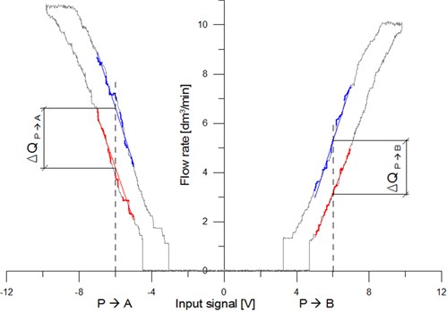
Table 1Obtained results of determined hysteresis
Fractional factorial experiment | Hysteresis at 6 V input signal | Standard deviation of hysteresis | ||||||||||
No. | [Hz] | [%] | [%] | [%] | [%] | [%] | () [%] | () [%] | () [%] | () [%] | ||
P-B | P-B | P-A | P-A | P-B | P-B | P-A | P-A | |||||
1 | –1 | –1 | 29 | 1.2 | 12.3 | 13.6 | 15.7 | 17.7 | 1.70 | 1.73 | 1.68 | 2.03 |
2 | –1 | 1 | 29 | 6.8 | 7.4 | 8.9 | 8.4 | 9.8 | 0.09 | 0.71 | 0.56 | 1.25 |
3 | 1 | –1 | 71 | 1.2 | 16.7 | 18.1 | 19.8 | 21.3 | 2.38 | 1.66 | 1.53 | 1.58 |
4 | 1 | 1 | 71 | 6.8 | 8.7 | 9.9 | 9.8 | 10.8 | 0.60 | 0.14 | 0.97 | 0.89 |
5 | –1.41 | 0 | 20 | 4 | 7.6 | 9.0 | 8.3 | 9.4 | 1.46 | 1.68 | 0.94 | 0.99 |
6 | 1.41 | 0 | 80 | 4 | 10.9 | 12.0 | 14.5 | 15.8 | 1.10 | 1.38 | 1.20 | 1.59 |
7 | 0 | –1.41 | 50 | 0 | 18.8 | 19.6 | 21.9 | 23.8 | 1.55 | 1.65 | 1.74 | 1.51 |
8 | 0 | 1.41 | 50 | 8 | 7.2 | 8.1 | 7.6 | 9.3 | 0.55 | 0.31 | 0.83 | 1.25 |
9 | 0 | 0 | 50 | 4 | 9.2 | 10.2 | 8.9 | 10.9 | 0.77 | 0.99 | 0.48 | 0.95 |
As can be easily seen, the tested directional control valve is characterized by some asymmetry. With the flow in the direction P→A, the valve demonstrates significantly larger hysteresis. In this position, there is probably less clearance between the spool and the bush. However, the differences in maximum values of flow in the directions P→A and P→B result from the asymmetrical throttling grooves on the control edges of the spool of the directional control valve. The partial points for the adopted Dither current settings are presented in Table 2.
Table 2Scoring for average hysteresis
Fractional factorial experiment | Hysteresis at 6 V input signal | Scoring for average hysteresis | |||||||
No. | [Hz] | [%] | [%] | [%] | [%] | [%] | |||
P-B | P-B | P-A | P-A | ||||||
1 | –1 | –1 | 29 | 1.2 | 12.3 | 13.6 | 15.7 | 17.7 | 2 |
2 | –1 | 1 | 29 | 6.8 | 7.4 | 8.9 | 8.4 | 9.8 | 3 |
3 | 1 | –1 | 71 | 1.2 | 16.7 | 18.1 | 19.8 | 21.3 | 1 |
4 | 1 | 1 | 71 | 6.8 | 8.7 | 9.9 | 9.8 | 10.8 | 3 |
5 | –1.41 | 0 | 20 | 4 | 7.6 | 9.0 | 8.3 | 9.4 | 3 |
6 | 1.41 | 0 | 80 | 4 | 10.9 | 12.0 | 14.5 | 15.8 | 2 |
7 | 0 | –1.41 | 50 | 0 | 18.8 | 19.6 | 21.9 | 23.8 | 0 |
8 | 0 | 1.41 | 50 | 8 | 7.2 | 8.1 | 7.6 | 9.3 | 3 |
9 | 0 | 0 | 50 | 4 | 9.2 | 10.2 | 8.9 | 10.9 | 3 |
In order to evaluate the obtained results, the following range of hysteresis value and corresponding score-based assessment were adopted: below 5 % – 4 points, 5-10 % – 3 points, 10-15 % – 2 points, 15-20 % – 1 point, above 20 % – 0 points.
3. Impact of the Dither current on the pressure pulsation in the hydraulic system
For each parameter setting the authors analyzed pulsation of pressure on the outflow of the piston chamber when the piston rod extended. Such a procedure was adopted intentionally in order to make the measurement independent of the pulsation generated by the pump. The illustrative pressure characteristics in the piston chamber are presented in Fig. 2.
Pressure pulsation in the outflow chamber was the result of changes in the hydraulic resistance on the edges of the directional control valve, caused by vibration [9] induced by the way proportional electromagnets are powered.
Fig. 2The exemplary course of pressure in the piston chamber of tested actuator: a) the course of a full cycle, b) enlarged section of the course (linefeed of the actuator) [10]
![The exemplary course of pressure in the piston chamber of tested actuator: a) the course of a full cycle, b) enlarged section of the course (linefeed of the actuator) [10]](https://static-01.extrica.com/articles/15393/15393-img2.jpg)
a)
![The exemplary course of pressure in the piston chamber of tested actuator: a) the course of a full cycle, b) enlarged section of the course (linefeed of the actuator) [10]](https://static-01.extrica.com/articles/15393/15393-img3.jpg)
b)
Table 3 provides the values of pressure pulsation (peak to peak) for the subsequent Dither current settings [11]. In order to evaluate the obtained results, the following range of pressure pulsation to its average value ratio and the corresponding score-based assessment were adopted: below 2.5 % – 4 points, 2.5-5 % – 3 points, 5-7.5 % – 2 points, 7.5-10 % – 1 point, above 10 % – 0 points.
Table 3The partial points for the impact of Dither current on the pressure pulsation
No. | [Hz] | [%] | Pressure in rod chamber [bar] | Peak to Peak (average) [%] | Scoring | |||
1 | –1 | –1 | 29 | 1.2 | 16.20 | 0.123 | 0.76 | 4 |
2 | –1 | 1 | 29 | 6.8 | 16.68 | 1.849 | 11.08 | 0 |
3 | 1 | –1 | 71 | 1.2 | 16.22 | 0.138 | 0.85 | 4 |
4 | 1 | 1 | 71 | 6.8 | 16.56 | 0.315 | 1.90 | 4 |
5 | –1.414 | 0 | 20 | 4 | 16.45 | 0.945 | 5.74 | 2 |
6 | 1.41 | 0 | 80 | 4 | 16.13 | 0.105 | 0.65 | 4 |
7 | 0 | –1.414 | 50 | 0 | 15.22 | 0.120 | 0.79 | 4 |
8 | 0 | 1.41 | 50 | 8 | 16.13 | 0.821 | 5.09 | 2 |
9 | 0 | 0 | 50 | 4 | 16.06 | 0.349 | 2.17 | 4 |
As can be seen, the pressure pulsation depends to a large extent on the Dither current amplitude for the frequencies lower than the limit frequency of the directional control valve (circa 41 Hz, estimated based on the step response). When Dither current exceeds the limit frequency, impact of the excitation on the pressure pulsation declines. It can be noticed observing the 71 Hz current. Nearly sixfold increase of the Dither current amplitude caused only twice as high pulsation, notabene of insignificant value.
4. Impact of Dither current on the vibration of cylinder’s piston rod
In order to determine the impact of pressure pulsation caused by Dither current on the vibration transduced from the hydraulic cylinder to the powered machine, the cylinder’s piston rod of the tested system was equipped with the accelerometer positioned in the direction of the piston rod axis. The registered acceleration of the longitudinal vibration of the piston rod was thereafter subject to the frequency analysis (applying FFT method). The illustrative longitudinal vibration spectrum of the cylinder was shown in Fig. 3. The measurements were taken applying the resolution of 0.381 Hz.
Fig. 3Spectrum of axial acceleration of rod for 4 variant of Dither’s parameters
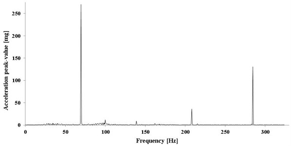
For each variant of Dither current settings we have determined the amplitude spectrum of acceleration corresponding to the frequency of the excitation (current), the same basis was used to determine the amplitude of the velocity of longitudinal vibration (Table 4). Acceleration values are the measure of the dynamic impact the cylinder has on the powered machine; the values of vibration velocity show the vibration energy that the cylinder sends to the machine.
As can be easily noticed, lower amplitude Dither current did not cause pulsation of the cylinder’s piston rod. Only starting from the amplitude 6.8 % one could notice peaks corresponding to the frequency of Dither current in the spectrum of axial acceleration of the piston rod.
Table 4Results of the FFT analysis
No. | [Hz] | [%] | real | [mg] | [m/s2] | [mm/s] | Scoring | ||
1 | –1 | –1 | 29 | 1.2 | – | – | – | – | 4 |
2 | –1 | 1 | 29 | 6.8 | 27.8 | 493.60 | 4.84 | 27.72 | 0 |
3 | 1 | –1 | 71 | 1.2 | – | – | – | – | 4 |
4 | 1 | 1 | 71 | 6.8 | 69.4 | 270.70 | 2.66 | 6.09 | 3 |
5 | –1.41 | 0 | 20 | 4 | 19.8 | 182.90 | 1.79 | 14.42 | 2 |
6 | 1.41 | 0 | 80 | 4 | – | – | – | – | 4 |
7 | 0 | –1.41 | 50 | 0 | – | – | – | – | 4 |
8 | 0 | 1.41 | 50 | 8 | 46.2 | 593.50 | 5.82 | 20.06 | 0 |
9 | 0 | 0 | 50 | 4 | 46.2 | 166.00 | 1.63 | 5.61 | 3 |
Using the multi-criteria optimization of Dither current optimal settings have been determined. The following criteria to optimize were adopted: the valve hysteresis value ( – as a percentage of maximum flow rate), the amplitude of pressure pulsation in a power line and a chamber of the powered actuator () and amplitudes of displacements and accelerations of the piston rod ().
The Table 5 summarizes results of the scoring and adopted weights of the individual effects at the Dither current intensities in case of the D1FB proportional valve [12, 13].
Table 5The results of multi-criteria optimization of Dither current intensity settings
Variations of Dither current intensity (scoring 0-4) | |||||||||||||
0.75 | 0.75 | 1.5 | 2 | 3 | 1 | 3 | 3 | 2 | 0 | 3 | 3 | ||
0,25 | 0.5 | 0.75 | 4 | 0 | 4 | 4 | 2 | 4 | 4 | 2 | 4 | ||
0,25 | 0.5 | 0.75 | 4 | 0 | 4 | 3 | 2 | 4 | 4 | 1 | 3 | ||
9 | 4.5 | 7.5 | 9.75 | 7.5 | 9 | 6 | 6.8 | 9.75 | |||||
[%] | 75 | 37.5 | 62.5 | 81.25 | 62.5 | 75 | 50 | 56.25 | 81.25 | ||||
The weight of each criterion was adopted within the experience of the authors and the desire to obtain good static properties of the hydraulic system of proportional valves.
5. Conclusions
The test results clearly indicate that the hysteresis of the proportional directional control valve is much more sensitive to the Dither amplitude than to its frequency. At the same time, it was discovered that with low Dither frequencies, below the limit frequency of the valve, we may observe unfavorable pressure pulsation and cylinder’s piston rod vibration in the hydraulic system. This may result in the resonance of the powered machine and in the worst case it might even cause damages to the machine, therefore users should use the Dither current intensity frequency above the frequency limit of the valve. At the same time should increase current amplitude with a simultaneously increasing frequency (as indicated by the results of multi-criteria optimization, settings and best meet described criteria).
Therefore, the users should adopt possibly high values of amplitudes and frequency of Dither current. However, one should also remember that Dither might cause piston rod pulsation inducing vibration in the powered machine. Thus, in order to prevent any resonance in the powered machine, valve manufacturers need to enable advanced users to select Dither settings themselves. Thanks to free selection of its frequency (and amplitude) it is possible to avoid unfavorable dynamic events while retaining proper static characteristics (low hysteresis).
It can be observed that not all manufacturers of proportional valves provide the users with full (to a reasonable extent) freedom when it comes to selecting settings. At the same time, it is underlined that the obtained results do not take into account the impact of Dither current on the valve life. It should be assumed that vibration of the mobile elements of proportional valves with large displacement amplitudes may be the cause of their premature wear. In order to prove this theory, it is necessary to do further research.
References
-
Pizoń A. Electro Hydraulic Analog and Digital Automation Systems. WNT Publishing House, Warsaw, 1995, (in Polish).
-
Milecki A. Linear Electrohydraulic Servo Drives. Poznan University of Technology Publishing, Poznan, 2003, (in Polish).
-
Tomasiak E., Klarecki K., Barbachowski E. Servo drives in machine construction. Hydraulics and Pneumatics, 2009, p. 16-20, (in Polish).
-
Buchacz A., Placzek M., Wrobel A. Control of characteristics of mechatronic systems using piezoelectric materials. Journal of Theoretical and Applied Mechanics, Vol. 51, Issue 1, 2013, p. 225-234.
-
Barbachowski E., Klarecki K. Methods for correcting the characteristics of proportional valves. Selected Engineering Problems, Vol. 2, 2011, p. 29-34, (in Polish).
-
Wszołek G., Czop P., Skrobol A., Sławik D. A nonlinear, data-driven model applied in the design process of disc-spring valve systems used in hydraulic dampers. Simulation Transactions of the Society for Modeling and Simulation International, Vol. 89, Issue 3, 2013, p. 419-431.
-
Wszołek G., Czop P., Sławik A. Development of an optimization method for minimizing vibrations of a hydraulic damper. Simulation Transactions of the Society for Modeling and Simulation International, Vol. 89, Issue 9, 2013, p. 1073-1086.
-
Gwiazda A. Construction development using virtual analysis on the example of a roof support. Applied Mechanics and Materials, Vol. 474, 2014, p. 417-422.
-
Dzitkowski T., Dymarek A. Active reduction of identified machine drive system vibrations in the form of multi-stage gear units. Mechanika, Vol. 20, Issue 2, 2014, p. 183-189.
-
Materials developed by Parker Hannifin. Direct Operated Proportional DC Valve Series D1FB, http://www.parker.com/.
-
Mannesmann Rexroth AG. The Hydraulic Trainer. Proportional and Servo Valve technology. Mannesmann Rexroth AG, Vol. 2, Lohr a. Main, 1998, (in German).
-
Gendarz P., Rabsztyn D. The exemplar design features in creation of the series of types. Journal of Achievements in Materials and Manufacturing Engineering, Vol. 55, Issue 2, 2012, p. 488-497.
-
Gendarz P. Assignments in the process of creating modular systems of constructions. Forschung Im Ingenieurwesen-Engineering Research, Vol. 73, Issue 4, 2009, p. 245-255, (in German).
About this article

