Abstract
Air filters was designed for air cleaning. They extends automotive and industrial devices life, because it cleans absorbing air from environment. For example it cleans air for internal combustion engines, air compressors, air conditioners and so on [1]. For better air cleaning it is necessary to create air filter housing model and make air flow calculations. Calculation results helps to adapt additional elements for longer air filter element life and better air filtration. During calculations was found one of the best technical solutions for better air filtration. Designed part was produced using 3D printer. Later with assembled filter some measurements and experiments were made. This article presents air flow pressure drop in air filter with different inner liners.
1. Introduction
Many scientists investigate air flows, performing highly complex calculations [2, 3]. It is necessary because sometimes impossible to measure air flow trajectories. During overview was found that there is not a lot of information about vehicle air filter flow analysis. Usually there are some measurements of the debit or pressure drop and etc. [4, 5].
This study was based on the air filter construction, because if the air filters size is high, it is necessary to use some internal elements to increase filter strength. However an additional element changes the air flow trajectories and may affect intake air parameters.
1.1. Air flow simulation of air filter inner liner
Air filter inner liner is one of the most important component of its construction. Because this component acts as support structure and as air flow handling tool, which prolongs the life of the filtering material. Continuing theoretical research of inner liner modeling [6] using “SolidWork 2014” software, old type (Fig. 1(a)) and new type inner liner components were modeled (Fig. 1(b)).
Fig. 1Preparation for further research, printed 3D models from ABS plastic

a) Printed original inner liner
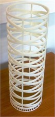
b) Printed new design inner liner
After many theoretical calculations was found that the new design inner liner is 15 grams lighter, has greater rigidity [6] and makes better air flow with lower resistance (Fig. 2). Rigidity calculation results show that new design inner liner has about 4 times smaller displacements with the same load then original inner liner component [6]. Also the new design inner liner has allowed to use a wider volume of the air filter box (about 10 %). However, this element creates lower air resistance of vehicle air intake system.
Fig. 2Air flow simulation results: a) using original inner liner, b) using new design inner liner
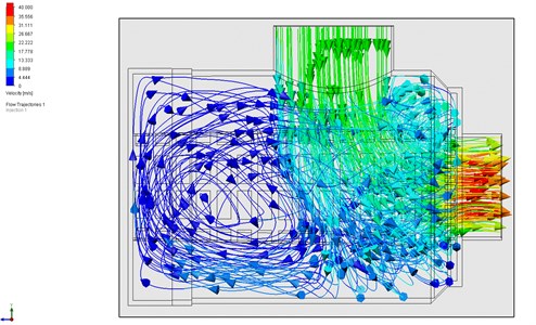
a)
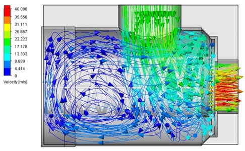
b)
1.2. Experimental research using wind tunnel
Experimental research results were carried out using “AEROLAB” wind tunnel (Fig. 3(a)). Taking into account of the wind tunnel test section size, model was reduced by 2 times. The air filter housing size was also reduced. Installed model is shown in Fig. 3(b).
Experiment was carried out using pressure sensor, pipes and special measuring probe. This probe measures pressure drop between air filter and fan. Measurement scheme of this experiment is shown in Fig. 4. This figure shows the air filter housing with inserted air filter element. Incoming air flow crosses the air filter material, inner liner element and moves out. Fig. 4(b) shows the measuring probe which was inserted in to the center of the model. This probe was able to move along the filter element. Probe location was measured between air filter housing bottom and probe tip. This distance is marked in Fig. 4(b) and marked “Probe distance”.
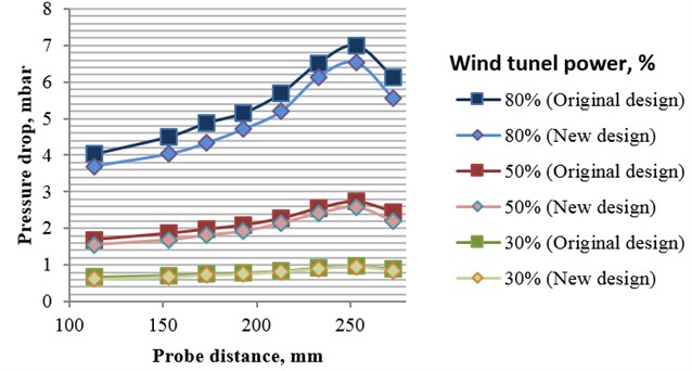
Experimental research was done using different wind tunnel power and selected positions of the probe. Measured pressure drops are shown in Fig. 5.
Measured results of pressure drop shows that higher result means the worse the air-pass of the filter. Seeing that air filter material on both models is the same, so inner liner element can be judged. In both filters, pressure drop increases towards the end part of filter. When wind tunnel power is increased the slope of pressure drop along the filter rises. When comparing air filters with original and new design inner linear elements in wind tunnel, higher static pressure drop is observed inside filter with original design. This indicates that less air flow passes through.
Fig. 3Test stand for pressure drop experiment: a) “AEROLAB” wind tunnel, b) air filter housing with installed air filter with new design inner liner model
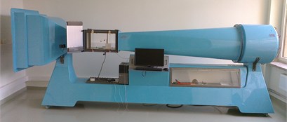
a)
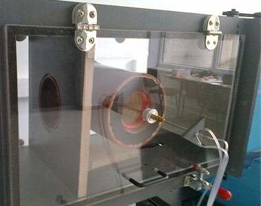
b)
Fig. 4Air filter housing with installed air filter model: a) side view; b) cross section of air filter housing
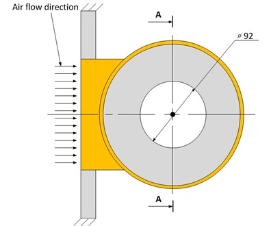
a)
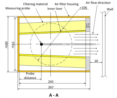
b)
Fig. 5Pressure drop dependency on probe location at various wind tunnel power
2. Conclusions
After theoretical calculations and experiments research was found that the filter with new design inner liner element produces less pressure drop when compared with original design inner liner element. During experiments was found that when wind tunnels power is 30 % the difference between filters are 4.9 %, when 50 %, it’s 8.4 % and when 80 % difference reaches 9.4 %. This result indicates that new design inner linear is significantly better than original design filter.
More experiments must be performed, including measurement of all spectrum of pressure inside filter and accurate debit measurement.
References
-
http://donaldsonlatam.com/cont/images/pdf/Gts/.
-
Fedaravičius Algimantas, Jonevičius Vaclovas, Kilikevičius Sigitas, Paukštaitis Linas, Šaulys Povilas Estimation of the drag coefficient of mine imitator in longitudinal air flow using numerical methods. Transport: Research Journal of Vilnius Gediminas Technical University and Lithuanian Academy of Sciences, Vol. 26, Issue 2, 2011, p. 166-170.
-
Kilikevičius Sigitas, Česnavičius Ramūnas, Šeibutas Paulius Experimental investigation and numerical simulation of airflow produced by a vertical recuperator. Mechanika, Proceedings of the 19th International Conference, 2014, p. 122-125.
-
http://www.homeenergy.org/show/article/id/667.
-
http://blog.consumerpla.net/.
-
http://ktu.edu/uploads/files/fakultetai/Mechanikos%20in%C5%BEinerijos%20ir%20dizaino%20fakultetas/files/Programme-Mechanika_2015(1).pdf.
About this article

