Abstract
In this paper the forced oscillations of the two-mass model of vibrating machine excited by inertial exciter driven by an electric drive of limited power are considered. For given mass of the working body and parameters of its oscillations the relationships between parameters of the machine were established, and the rational dynamic regimes with low energy consumption and low dynamic forces transmitted to its base were defined.
1. Introduction
One of the problems in creating high-performance vibrating machines is to ensure the required mode oscillation while reducing power consumption and dynamic loads transmitted to the base. The most of modern vibrating machines are based on single-mass dynamical scheme with excitation in above-resonance modes due to their high stability. However, they have quite low exciting force efficiency and low dynamic balance [1-6].
One possible solution is to use a multi-mass dynamic scheme, for example, two-mass scheme for vibrating machines. It is known [1-3, 6] that the introduction of extra mass increases the dynamic balance of the machine, improving its vibration isolation, which allows to operate at a resonant or near-resonant mode. In this case, as it is known [3, 7-10], an oscillatory system is able to significantly impact on the energy source depending on the ratio of input energy to dissipated one, and can lead to freeze at a certain frequency or to jump in frequency and amplitude of oscillations - the so-called Sommerfeld effect [3, 7-10].
The requirements to trajectories and oscillation parameters of the machine's working body generally are the main criteria when selecting oscillation regime. For example, in machines for vibro-transportation, vibro-classification and many other vibrating processes, based on the effect of the vibro-motion it is often required for given mass of the working body to ensure its unidirectional oscillation with certain amplitude of vibratory velocity, i.e. with certain relation between the oscillation frequency and amplitude. It is evident that this can be achieved by appropriate selection of mechanical parameters of the oscillating system and its dynamic mode, while taking into account requirements to reduce power consumption and dynamic forces transmitted to the base leads to formulation of rational design problem.
In this paper, we consider a model of vibrating machine in the form of a system of two rigid bodies connected with each other and with the fixed base by viscoelastic dampers, which are performing unidirectional oscillations excited by inertial exciter driven by limited power electric drive. It is assumed that the working body weight is given in advance and is not changed during operation of the machine. At the same time to achieve desired efficiency of implemented process it is necessary to ensure a predetermined level of vibratory velocity of the working body. In order to choose rational operating modes and parameters of the machine an analysis of its frequency response, power relationships and dynamic forces is carried out at different oscillation modes.
2. The model
Dynamic scheme of the machine is shown in Fig.1. It consists of a working body with a payload, simulated together by a rigid body of mass , and a platform with unbalanced exciter rigidly attached to it, simulated by a rigid body of mass .
The working body and the platform are connected with each other and with fixed base by viscoelastic dampers having linear characteristics of stiffness , and viscous friction , respectively. The working body and the platform are able to move only in vertical direction without any friction with side guides. Vibration exciter has unbalanced mass and eccentricity . Driving torque acting from the motor on the rotor of the exciter, having moment of inertia , is described by its static characteristic . Friction in bearing of the exciter rotor and the electric motor is taken into account as a reduced moment of viscous friction forces proportional to their angular speed.
Fig. 1Dynamic scheme of vibrating machine
Motion of the system is considered relative to a fixed coordinate system with the origin at the center of mass of the working body and the positive direction of the axis corresponds to the direction vertically downward in Fig. 1. Motions of the working body and the platform are described by displacements of their centers of masses and from their positions of static equilibrium, respectively. Angular position of debalance is determined by angle , measured from the lower vertical position.
Equations of motion, in dimensionless terms [11]:
where the following dimensionless variables and parameters are used: time displacements , , time scale factor , displacements scale factor , where and , and the system parameters: , , () and () denote the first and the second derivative with respect to dimensionless time , respectively.
3. Ensuring the required oscillations of the working body
According to the statement of the problem it is required to provide a predetermined level of the vibration velocity amplitude of the working body regardless of oscillation mode, that is mathematically expressed by the condition:
where – amplitude of the working body oscillations, – oscillations frequency. As it follows from Eq. (2) the choice of oscillation mode is determined by relation between the amplitude and frequency of the working body oscillations depending on the parameters of the oscillatory system. To obtain these relations let’s consider dynamic model of the machine taking into account ideal power source of the unbalanced exciter drive. In this case we can take , and equations of motion are:
Note, that introduction of this assumption excludes the possibility to estimate ability to realize and stability of a particular mode when using certain type of drive, but makes it significantly easier to obtain the required relations at the considered here steady-state oscillation modes without making any significant mistakes.
System of equations Eq. (3) is the system of two linear differential equations with constant parameters. The solution of Eq. (3) corresponding to steady-state forced oscillations is obtained by the method of complex amplitudes in the following form , , where , and , – are amplitudes and phase shifts of the moving masses oscillations respectively. As a result, the relations for determining amplitudes are:
Fig. 2Frequency response of the system
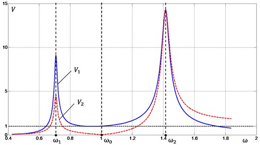
Fig. 2 shows frequency response of the system in terms of the vibrospeed amplitudes and for the moving masses and respectively. For certainty of further discussion, we take 1. Substituting Eq. (4) into Eq. (3) we obtain relation between the parameters of the system for which the required level of vibration is provided regardless of the mode of the system oscillation:
It is evident that Eq. (6) is satisfied for infinite number of combinations of the system parameters. In practice only few of these parameters could be changed. For example, it is difficult, and sometimes even practically impossible, to change stiffness of the springs and dissipative system parameters, changing the value of the moving mass is usually possible only in enlarging weight, due to ballast weights, which results also in an increase in energy losses. Adjustment of the exciting force value by appropriate selection of the debalance parameters determined by the parameter seems to be the most practical and realistic method. Note that for given other parameters of the system the value of is determined from Eq. (6) depending on the angular velocity of debalance which could be chosen in different ways. Let’s try to exclude this indefiniteness in choice by requiring to decrease power consumption and forces transmitted to the machine base. In considering further problems all the parameters in Eq. (6), except for and assumed to be given.
4. Dynamic forces transmitted to the machine base
To determine forces transmitted to the base at steady-state oscillations of the machine the model of the machine described by Eq. (3) will be used. As it follows from Fig. 1 this force is a sum of resilient force of the spring and force of viscous friction in dissipative element , and is defined by the expression:
where and are defined from solution of Eq. (3) taking into account Eq. (6). Since Eq. (3) is linear, so the force , as well as and , is harmonic with respect to time.
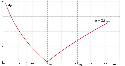
Diagram of the force amplitude with respect to frequency for different values of is shown in Fig. 3. The following values of the system parameters were taken in calculations: 3, , , . It is seen that function reaches its minimum at frequency corresponding to so-called “antiresonace frequency” of the system. The parameter , essentially characterizing the dissipation magnitude of the lower damper, does not affect the character of this relation, and significant difference in magnitude of transmitted force is observed only in the frequency range above the second resonance, i.e. when .
Fig. 3Dynamic forces transmitted to the base
5. Forces of resistance to oscillatory motion
In the implementation of technological process, the machine energy is spent on excitation of vibrations and overcome the friction in the bearings of the shafts of vibration exciter and electric drive. Thus, the energy costs of the process are determined by the moment of resistance to oscillatory motion acting onto the drive of exciter from the oscillatory system, and the reduced moment of friction forces in the shafts bearings of the exciter and drive. To estimate these forces, consider a dynamic model of the machine, described by Eq. (1). Solutions corresponding to the steady motion of the system will be found in approximate form by the method of perturbation theory of N. N. Bogolyubov [7, 12].
Following the above mentioned method, we represent the solution of Eq. (1) through its generalized coordinates and : , , where (, 1, 2) – are coefficients of shape functions corresponding to its eigenfrequencies . The solution for each of these coordinates will be found in the form of , taking into account relations , , where , and are slowly changing in comparison with the basic period of oscillation functions of time. Consider the first approximation of the solution. Here we take into account that oscillations described by coordinates are small in comparison with when considering the motion of the system near the frequency , so we can neglect in obtaining solution in the first approximation. Similarly, when considering the motion of the system near the resonance , oscillations described by are small in comparison with .
Thus, we obtain the following expression for determining the amplitude and frequency of vibrations:
– near the resonance :
where ;
– near the resonance :
where .
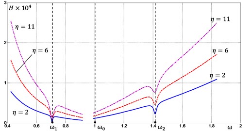
Fig. 4Forces of resistance to oscillatory motion
Eq. (11), (13) represent equation of balance of driving torque and moment of resistance to oscillatory motion:
and allow to determine possible motions of the system.
Let us estimate the moment of resistance to oscillatory motion taking into account requirement of ensuring a predetermined vibration of the machine working body, regardless of the excitation frequency, i.e. taking into account Eq. (6). The corresponding relations for different values of are graphically shown in Fig. 4. One can see that the character of functions is independent of the value of , but increase in leads to increase in moment of resistance . The functions have local minimums at the frequencies corresponding to the eigenfrequencies and of the system and near its “antiresonance” frequency .
6. Conclusions
The model of vibrating machine and results of its dynamics analysis presented in this work shows that when choosing an oscillation mode of the two-mass vibrating machines with the requirement to ensure a predetermined magnitude of the working body vibration it is preferable to tune the system to the frequency in the range from the first to the second eigenfrequencies, because of possible achievement of the lowest forces transmitted to the base and the lowest power consumption for implementation of the desired technological process. The magnitudes of damping of both the upper and the lower dissipative elements should be reduced as much as it possible when designing machine, as it causes a monotonic almost proportional increase in moment of resistance to oscillatory motion, thereby increasing the energy costs of the technological process, but unlike the upper element an increase in damping in the lower element does not lead to a significant change in the force transmitted to the base.
References
-
Vulfson I. I. Dynamics of Cyclic Machines. Polytechnics, St-Petersburg, 2013.
-
Vaisberg L. A. Design and Calculation of Vibrating Screens. Nedra, Moscow, 1986.
-
Lavendelis E. E. Vibration Processes and Machines. Vibration in the Technique, Handbook, Vol. 4, Mechanical Engineering, Moscow, 1981, (in Russian).
-
Astashev V. K., Kolovsky M. Z., Babitsky V. I. Dynamics and Control of Machines. Springer-Verlag, Berlin Heidelberg, 2000.
-
Panovko G. Ya., Shokhin A. E., Eremeykin S. A. Control the resonance mode of vibrating machine driven by induction motor. Journal of Machinery Manufacture and Reliability, Vol. 2, 2015, p. 3-8.
-
Bihovsky I. I. Fundamentals of the Vibrational Technology Theory. Machinostroenie, Moscow, 1968.
-
Kononenko V. Oscillatory Systems with Limited Excitation. Nauka, Moscow, 1964, (in Russian).
-
Blekhman I. I. Vibrational Mechanics. Nonlinear Dynamic Effects, General Approach, Applications. World Scientific Publishing Co., Singapore, 2000.
-
Guskov A. M., Panovko G. Ya. Nonlinear effects at vibration of linear mechanical systems with centrifugal exciter of limited power. Engineering Journal: Science and Innovation, Vol. 6, Issue 6, 2012.
-
Niselovskaya E., Panovko G., Shokhin A. Oscillations of the mechanical system generated by an unbalanced rotor asynchronous electric motor. Journal of Machinery Manufacture and Reliability, Vol. 6, 2013, p. 17-23, (in Russian).
-
Shokhin A., Nikiforov A., Korendyasev G., Eremeykin S. Analysis of dynamic properties of two-mass system with inertial exciter of limited power. Vibroengineering Procedia, Vol. 6, 2015, p. 316-320.
-
Nayfeh A. H. Perturbation Methods. Wiley, New York, 2000.
About this article

The study was performed account for a grant of the Russian Science Foundation (Project No. 15-19-30026).
