Abstract
The problems of studying the dynamic behavior and improving the operational efficiency of various vibratory equipment are currently of significant interest. Special attention is paid to the possibilities of developing the enhanced designs of the planetary-type vibration exciters for the conveying, screening, and sieving machines. The novelty of the present research consists in providing the changeable inertial parameters of the improved planetary-type vibration exciter in order to adjust its operational conditions in accordance with the technological requirements. The mathematical model of the single-mass vibratory screening conveyor equipped with the proposed exciter is developed using the Lagrange-d’Alembert principle. The simulation of the system kinematic and dynamic characteristics under different operational conditions is carried out in the Mathematica software using the integrated Runge-Kutta methods.
Highlights
- The enhanced asymmetric self-regulated planetary-type vibration exciter is considered. The possibilities of changing its inertial characteristics and adjusting its operational conditions are studied.
- The improved mathematical model describing the dynamics of the single-mass vibratory screening conveyor equipped with the proposed planetary-type vibration exciter is developed.
- The exciter kinematic and dynamic parameters are simulated at different operational conditions. This allows for substantiating the control strategies to meat the prescribed technological requirements.
1. Introduction
The problems of vibration excitation of various industrial equipment are of significant interest among researchers and designers. The vibratory machine operational conditions and technological functions substantially depend on the implemented exciter. Among a great variety of vibratory drives, the planetary-type ones are widely used in compacting equipment, screening and conveying machines, etc. The self-resonance effect occurring during the operation of the planetary-type vibration exciters allows for their effective implementation in different areas of vibration engineering with no necessity to use the complicated control systems [1]. The dynamic behavior and the failure effects of the planetary gear mechanisms are investigated in [2]. The improved model of the planetary gearbox containing the time-varying parameters is considered in [3]. The kinematic and dynamic analysis of the asymmetric planetary-type vibration exciter is carried out in [4]. The problems of synthesizing the rational design parameters of an asymmetric planetary-type vibration exciter with a pendulum anti-skid device are studied in [5]. The paper [6] considers the self-regulated inertial vibration exciter able to adjust its geometrical and mass parameters in accordance with the required dynamic characteristics of the vibration process.
The possibilities of implementing the dual-frequency excitation of vibratory equipment by applying two synchronized coaxial unbalanced rotors driven by one electric motor are considered in [7]. Similar inertial vibration exciter equipped with separate driving motors independently actuating each unbalanced rotor was thoroughly studied in [8]. The novel design of the eccentric-pendulum-type inertial vibration exciter generating the periodic disturbing force along the prescribed direction is theoretically and experimentally investigated in [9]. The paper [10] is dedicated to designing and studying the operation of the planetary-type vibration exciter with two unbalanced masses synchronized with the help of the chain gear. In [11], the authors considered the three-mass vibratory machine operating under the anti-resonance conditions and actuated by the inertial vibration exciter designed in the form of the passive auto-balancer. The dynamics of the single-mass vibratory machine equipped with two identical inertial vibration exciters of the ball, roller, or pendulum type is analyzed in [12].
The present paper continues the authors’ previous research presented in [13] and [14] and dedicated to investigating the dynamics of the controllable inertial vibration exciters. Unlike the twin crank-type exciters thoroughly studied in [13] and [14] and implemented for providing the translational locomotion conditions of semidefinite vibratory systems and compaction machines, the present research considers the asymmetric self-regulated planetary-type vibration exciter. The novelty of this paper consists in improving the exciter design parameters by ensuring the possibility of changing its inertial characteristics and adjusting its operational conditions in accordance with the technological requirements. The proposed ideas can be effectively implemented in practice while designing the vibratory conveying and screening machines. The main objectives of this research consist in improving the mathematical model of the single-mass vibratory screening conveyor equipped with the proposed planetary-type exciter, and simulating the exciter kinematic and dynamic characteristics under different operational conditions.
2. Research methodology
2.1. General design of the vibratory screening conveyor equipped with the asymmetric self-regulated planetary-type vibration exciter
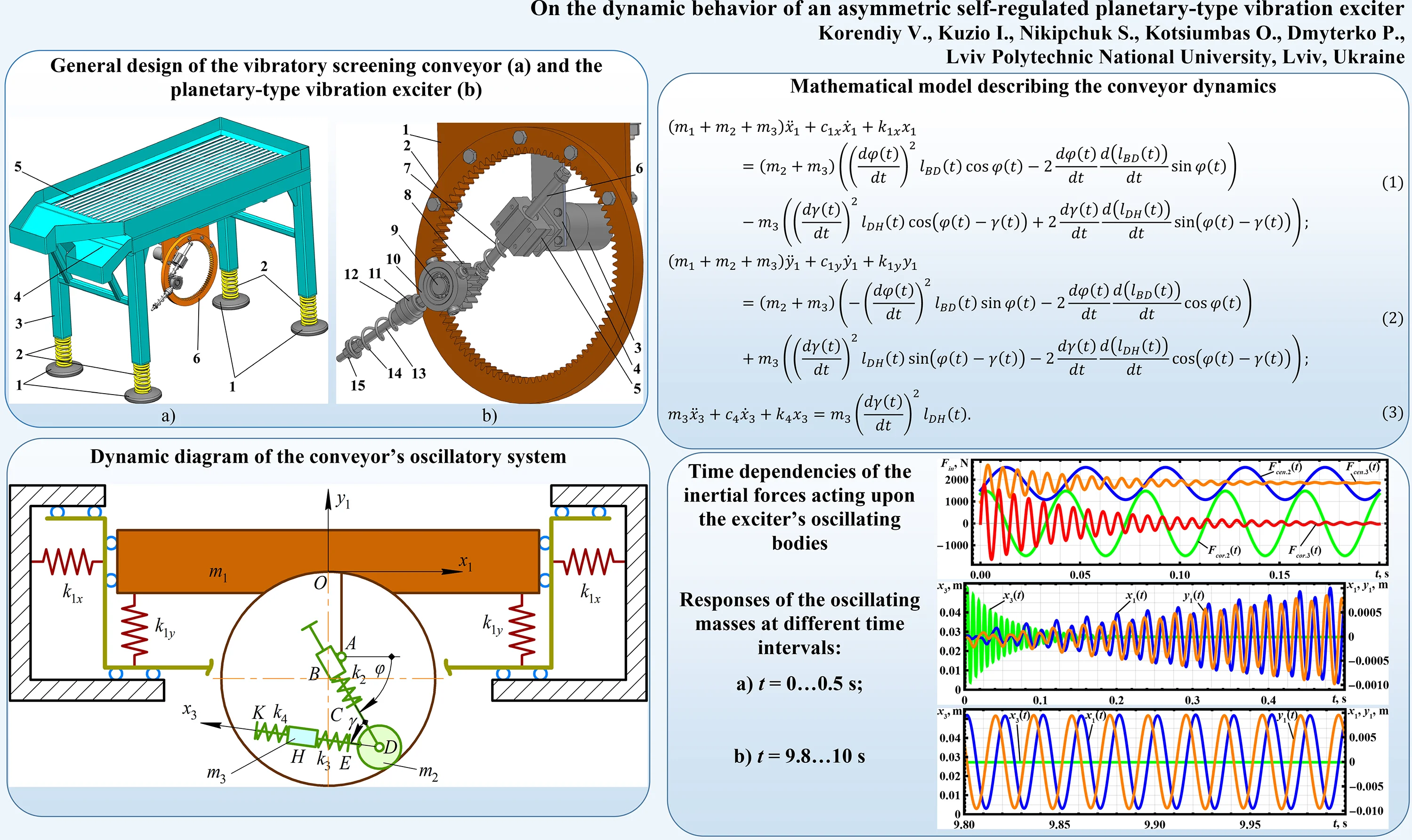
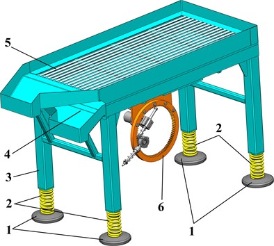
The vibratory screening conveyor is based on the single-mass oscillating platform 3 mounted on the foundation using four supports 1 and coil springs 2 (Fig. 1(a)). The working member consists of the vibrating screen 5 with the rod-type sieve and the conveying tray 4. The system is set into oscillatory motion by the asymmetric self-regulated planetary-type vibration exciter 6.
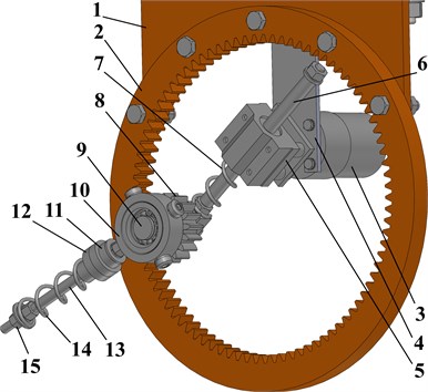
The improved design of the exciter is presented in Fig. 1(b). The plate 1 is used to connect the exciter to the conveyor’s oscillating platform. The ring (annual) gear 2 is fixed to the plate 1. The driving motor 3 is mounted on the plate 4 connected with the 2. The axis of the motor’s shaft rotation doesn’t coincide with the ring gear’s geometric center. That’s why the carrier bar 6 changes its position relative to the guide (linear) bearing 5 mounted on the motor shaft.
Fig. 1a) General design of the vibratory screening conveyor and b) the planetary-type vibration exciter
a)
b)
Using the ball bearings, the planet gear 8 is installed on the axis 9 fixed to the carrier bar 6 (Fig. 1(b)). The planet gear 8 rolls on the inside of the ring gear’s pitch circle 2. In order to ensure reliable contact between the planet gear 8 and the ring (annual) gear 2, the position of the carrier bar 6 sliding along the guide (linear) bearing 5 is regulated by the coil spring 7. The guiding bar 13 of the centrifugal exciter is connected to the casing 10 fixed on the ring gear’s hub 8. The unbalanced weights are placed on the guide (linear) bearing 12 sliding along the guiding bar 13. The position of the bearing 12 is controlled by the rubber damper 11 and the coil spring 14. The preliminary compression of the spring 14 is regulated by the nut 15.
Therefore, the rotation of the driving motor’s shaft 3 causes the rolling of the planet gear 8 along the inner circle of the ring gear 2 and simultaneous plane-parallel motion of the centrifugal weights 12. The major advantage of such an asymmetric planetary-type vibration exciter consists in arising the centrifugal and Coriolis forces and gyroscopic moments acting upon the planet gear 8 and the ring (annual) gear 2. The mentioned forces and moments significantly improve the dynamic characteristics of the planetary-type vibration exciter and increase the efficiency of the conveying and screening processes provided by the vibratory machine [2], [3]. Unlike the actual research results and designs of similar exciters, the proposed one allows for self-regulating the inertial parameters of the centrifugal unit, i.e., the position of the weights 12 (see Fig. 1(b)).
2.2. Dynamic diagram of the conveyor’s oscillatory system
Let us consider the simplified dynamic diagram of the vibratory screening conveyor whose working member performs vertical and horizontal oscillations while the angular motion is restricted (see Fig. 2). The working member (conveying tray and oscillating sieve) is simulated as the rigid body of the mass supported by the vertical springs of the stiffness . The horizontal displacement of the working member is limited by the horizontal springs of the stiffness . The oscillations are excited by the planetary-type mechanism consisting of the following elements: the ring (annual) gear fixed to the working member; the carrier bar characterized by the adjustable length; the planet gear rolling along the inner pitch circle of the ring (annual) gear; the unbalanced (centrifugal) exciter with self-regulated inertial characteristics.
Fig. 2Dynamic diagram of the conveyor’s oscillatory system
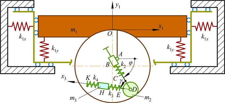
The rotary motion of the block linkage around the hinge simulating the motor shaft is determined by the controllable angle . The carrier bar can change its length in accordance with the position of the planet gear due to the action of the spring of the stiffness . The planet gear of the mass is hingedly joined with the carrier bar at the point . The guide bar of the unbalanced (centrifugal) exciter is fixed to the planet gear and simultaneously rotates around the hinges and . The angular position of the guide bar relative to the carrier bar is described by the angle . Therefore, the unbalanced mass simulated as the slider moving along the guide bar is generally under the conditions of the plane-parallel motion characterized by the changeable radiuses and . The distance is controlled by applying the certain parameters (stiffnesses , , initial lengths, etc.) of the springs , , and can change during the machine operation due to the action of the centrifugal and Coriolis forces.
2.3. Mathematical model describing the conveyor dynamics
Let us adopt the Cartesian coordinate system with its origin located at the gravity center of the conveyor’s working member (see Fig. 2). The generalized coordinates and unambiguously describe the position of the working member at any moment of time with respect to its initial position. The generalized coordinate is used to describe the sliding (translational motion) of the guide (linear) bearing (mass ) along the guide bar . The mathematical model describing the conveyor dynamics is developed using the Lagrange-d’Alembert principle. The differential equations of the oscillatory system motion are following:
where , , are the damping coefficients influencing the corresponding motion conditions of the oscillating bodies; ; is the initial angular position of the carrier bar relative to the horizontal axis; is the carrier bar angular velocity; ; ; is the pitch radius of the ring (annual) gear; , are the coordinates of the axis of the carrier bar BD rotation (hinge A, see Fig. 2); ; is the initial angular position of the guide bar DK relative to the carrier bar BD; is the pitch radius of the planet gear; ; , are the distances describing the initial position of the slider (unbalanced mass ).
3. Results and discussion
3.1. Analyzing the inertial forces acting upon the oscillating bodies
Let us introduce the input parameters: 157 rad/s, 0, 3.14, 300 kg, 0.8 kg, 0.05 kg, 0.02 m, 0.01 m, 0.087 m, 0.017 m, 0.015 m, –0.055 m, 3×10⁷ N/m, 100 (N∙s)/m, 6.8×10³ N/m, 2 (N∙s)/m. The results of numerical modeling are presented in Fig. 3.
Some of the internal forces do not exert any effect on the system dynamics. The carrier bar spring just presses the planet gear to the ring (annual) gear that’s why the stiffness is not specified. Similar conclusion can be drawn about the rubber spring element of the stiffness used for adjusting the initial position of the unbalanced mass.
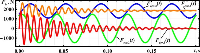
The inertial forces acting upon the oscillating bodies can be divided into the following groups: centrifugal forces , occurring due to the planet gear rolling along the inner pitch circle of the ring (annual) gear and due to the unbalanced mass rotation around the hinge (see Fig. 2), respectively; Coriolis forces , disturbed due to the simultaneous rotational and translational motions of the planet gear and the unbalanced mass taking place while changing the length of the carrier bar and the distance , respectively.
The maximal excitation effect on the system vibrations is exerted by the centrifugal forces , . The magnitude of the force varies within 1000,…, 2600 N and changes in time due to the periodic decreasing and increasing of the distance BD. The force magnitude becomes almost constant and reaches about 1800 N after a certain time interval when the position of the slider holding the unbalanced mass is stabilized. The overall influence of the Coriolis force on the system motion is somewhat smaller, and its magnitude periodically changes in time within –1500,…, 1500 N. The force exerts almost zero effect on the system when the position of the unbalanced mass becomes stable, i.e., when the translational speed of the slider moving along the guide bar is equal to zero (see Figs. 2, 3).
Fig. 3Time dependencies of the inertial forces acting upon the exciter’s oscillating bodies
3.2. Numerical modeling of the system motion
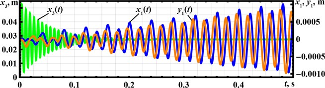
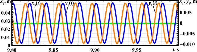
The next stage of the present investigation is dedicated to numerical modeling of the conveyor’s oscillatory system motion excited by the inertial forces considered above. The solution of the derived system of the differential Eq. (1)-(3) has been obtained in the Mathematica software using the integrated Runge-Kutta methods. The results of the carried out numerical modeling are presented in the form of time dependencies of the oscillating masses displacements (responses) at different time intervals characterizing the starting conditions and the stable operation of the vibratory conveyor (see Fig. 4).
Fig. 4Responses of the oscillating masses at different time intervals: a) t= 0…0.5 s; b) t= 9.8…10 s
a)
b)
The starting conditions are characterized by intensive oscillations of the unbalanced mass whose initial displacement reaches 54 mm (Fig. 4(a)). After a certain time interval, the mass takes its stable position at 0.028 m (Fig. 4(b)). The conveyor’s working member (screen and tray) starts its motion from the state of rest and performs periodic elliptical oscillations at the amplitude of about 10 mm, reaching the stable operation 1.5,…, 2 s after the start. According to the input data, the forced frequency is equal to 25 Hz ( 157 rad/s), while the working body oscillations are performed at about 50 Hz (see Fig. 4).
4. Conclusions
The paper deals with studying the dynamics of the enhanced asymmetric planetary-type vibration exciter used in the vibratory screening conveyor. Under the prescribed input parameters, the working member performs elliptical oscillations at the amplitude of about 10 mm.
The carried-out investigations showed that by changing the forced frequency and the ratio, it is possible to adjust the operational conditions in accordance with the technological requirements. At the same time, the amplitude values of the working body displacement, velocity, and acceleration can be easily controlled by changing the inertial parameters of the unbalanced mass, i.e., the mass value, initial position, stiffness , etc. Therefore, the scope of further investigations consists in optimizing the system parameters in accordance with the prescribed technological requirements set for various vibratory equipment.
References
-
K. Ragulskis, “The self-resonance effect of the planetary vibration excitation systems,” Journal of Vibroengineering, Vol. 14, No. 1, pp. 244–249, 2012.
-
Z. Xiao, J. Cao, and Y. Yu, “Mathematical modeling and dynamic analysis of planetary gears system with time-varying parameters,” Mathematical Problems in Engineering, Vol. 2020, pp. 1–9, Mar. 2020, https://doi.org/10.1155/2020/3185624
-
Y. Liu, D. Zhen, H. Zhang, H. Zhang, Z. Shi, and F. Gu, “Vibration response of the planetary gears with a float sun gear and influences of the dynamic parameters,” Shock and Vibration, Vol. 2020, pp. 1–17, Aug. 2020, https://doi.org/10.1155/2020/8886066
-
A. Kim, M. Doudkin, A. Ermilov, G. Kustarev, M. Sakimov, and M. Mlynczak, “Analysis of vibroexciters working process of the improved efficiency for ice breaking, construction and road machines,” Journal of Vibroengineering, Vol. 22, No. 3, pp. 465–485, May 2020, https://doi.org/10.21595/jve.2020.20446
-
M. Marek, G. Kustarev, and N. Andrjuchov, “Theoretical studies and conditions analysis of the inertial slider slippage of asymmetric planetary vibration exciter for snowplow,” Bulletin of D. Serikbayev EKTU, No. 3, pp. 63–78, 2021, https://doi.org/10.51885/1561-4212_2021_3_63
-
I. Lyan, K. Krestnikovskii, G. Panovko, and A. Shokhin, “Determination of mass-geometric characteristics of self-regulating debalance of an inertial vibration exciter,” Vibroengineering PROCEDIA, Vol. 25, pp. 70–75, Jun. 2019, https://doi.org/10.21595/vp.2019.20810
-
V. Gursky, I. Kuzio, P. Krot, and R. Zimroz, “Energy-saving inertial drive for dual-frequency excitation of vibrating machines,” Energies, Vol. 14, No. 1, p. 71, Dec. 2020, https://doi.org/10.3390/en14010071
-
V. Gursky, P. Krot, V. Korendiy, and R. Zimroz, “Dynamic Analysis of an Enhanced Multi-Frequency Inertial Exciter for Industrial Vibrating Machines,” Machines, Vol. 10, No. 2, p. 130, Feb. 2022, https://doi.org/10.3390/machines10020130
-
V. V. Mikheyev, “New type of vibration generator with vibratory force oriented in preferred direction,” Journal of Vibration Engineering and Technologies, Vol. 6, No. 2, pp. 149–154, Apr. 2018, https://doi.org/10.1007/s42417-018-0025-4
-
V. V. Mikheyev and S. V. Saveliev, “Planetary adjustable vibratory exciter with chain gear,” in Journal of Physics: Conference Series, Vol. 1210, No. 1, p. 012097, Mar. 2019, https://doi.org/10.1088/1742-6596/1210/1/012097
-
V. Yatsun, G. Filimonikhin, V. Pirogov, V. Amosov, and P. Luzan, “Research of anti-resonance three-mass vibratory machine with a vibration exciter in the form of a passive auto-balancer,” Eastern-European Journal of Enterprise Technologies, Vol. 5, No. 7 (107), pp. 89–97, Oct. 2020, https://doi.org/10.15587/1729-4061.2020.213724
-
G. Filimonikhin, V. Pirogov, M. Hodunko, R. Kisilov, and V. Mazhara, “The dynamics of a resonance single-mass vibratory machine with a vibration exciter of targeted action that operates on the Sommerfeld effect,” Eastern-European Journal of Enterprise Technologies, Vol. 3, No. 7 (111), pp. 51–58, Jun. 2021, https://doi.org/10.15587/1729-4061.2021.233960
-
V. Korendiy, V. Gursky, O. Kachur, V. Gurey, O. Havrylchenko, and O. Kotsiumbas, “Mathematical modeling of forced oscillations of semidefinite vibro-impact system sliding along rough horizontal surface,” Vibroengineering PROCEDIA, Vol. 39, pp. 164–169, Dec. 2021, https://doi.org/10.21595/vp.2021.22298
-
V. Korendiy et al., “Kinematic and dynamic analysis of three-mass oscillatory system of vibro-impact plate compactor with crank excitation mechanism,” Vibroengineering PROCEDIA, Vol. 40, pp. 14–19, Feb. 2022, https://doi.org/10.21595/vp.2022.22393
Cited by
About this article

