Abstract
One of the most intensively developing fields of vibratory technologies is focused on improving the design and operational parameters of the excitation mechanisms and drives. The present research is devoted to a novel twin crank-type exciter driven by a permanent-magnet direct-current motor. The research methodology consists of mathematical modeling and computer simulation of the dynamic behavior of a single-mass oscillatory system equipped with the proposed exciter. The obtained results substantiate the possibilities of generating rectilinear, elliptical, and circular oscillations of the working member by applying the corresponding design changes of the transformable vibration exciter. The major scientific novelty of the carried-out investigations consists in determining the influence of specific design parameters of the exciter on the trajectory (path) of the working member motion. The obtained results can have a significant practical value while designing new and improving existent drives of various vibratory equipment (screens, conveyors, sieves, compactors, technological (lapping, polishing) machines, etc.).
Highlights
- The enhanced twin crank-type exciter driven by a DC motor is developed and implemented in practice for controllable actuating various vibratory technological equipment (conveyors, sieves, screens).
- The dynamic diagram of the single-mass vibratory system equipped with the proposed exciter is considered, and the mathematical model describing its motion is derived using Euler-Lagrange equations.
- The simulation is performed in the Mathematica software and the results are presented in the form of trajectories of the working member at different angles of the sliders’ reciprocation directions.
- The possibilities of generating circular, elliptical, and rectilinear vibrations of the working member depending on the operation (conveying, screening, sieving, compacting, etc.) are substantiated.
1. Introduction
Among a great variety of technological operations that can be provided with the help of vibratory equipment, the conveying, screening, sieving, and compacting ones are of the most widely used. Numerous scientific investigations are devoted to different aspects of the implementation and improvement of vibration machines. For example, the paper [1] considers the possibilities of controlling the conveying speed and direction by means of changing the excitation conditions of a vibrating table. The improved (more accurate) mathematical model of a flip-flop vibratory screen loaded by the materials being processed is derived in [2]. The prospects of performing the diagnostical operations and predicting the service life of the vibrating screens are thoroughly studied in [3]. Considering the performance of the vibratory screening equipment, the authors of [4] investigated the influence of the external moisture content and the screen type on the efficiency of stratification and dewatering of different materials. Also, the vibratory technologies can be effectively implemented while performing the high-temperature reduction and reoxidation of different metals [5]. In most cases, the performance of the specific vibratory technological operation (conveying, screening, sieving, compacting, etc.) significantly depends on the design and operational parameters of the implemented vibration exciter [6].
One of the major tasks set for a designer of the vibratory equipment consists in providing the prescribed trajectory (path) of the working member (conveying tray, screen, sieve, etc.). The possibilities of controlling the dynamic parameters of different vibratory systems equipped with centrifugal vibration exciters (unbalanced rotors) are comprehensively studied in [7] and [8]. The enhanced designs of inertial exciters based on the planetary-type mechanisms are presented and simulated in [9] and [10]. The paper [11] considers the dynamics of the single-mass oscillatory system actuated by the crank-type excitation mechanism. In [12], the author proposed a novel design of the inertial vibration exciter that can provide the prescribed direction of the periodic disturbing force. The possibilities of increasing the excitation force by applying the asymmetric planetary-type vibrators are substantiated in [13]. The paper [14] is dedicated to investigating the Sommerfeld effects associated with the non-linear jump phenomena during the operation of a single-mass vibratory system equipped with a crank-type excitation mechanism and DC motor.
In most cases, the existent vibration exciters can only change the forced frequency, while their design parameters usually cannot be transformed during the machine operation. In [15], the authors made an attempt to develop the crank-type excitation mechanism allowing for adjusting its inertial parameters (eccentricity) according to the prescribed technological requirements. The paper [16] was focused on implementing the enhanced crank-type exciter for actuating the shaking screening conveyor. In [17], the authors studied the dynamic behavior of a wheeled locomotion system equipped with the considered crank-type excitation mechanism. The present research is devoted to a novel twin crank-type exciter driven by a permanent-magnet direct-current motor. The major scientific novelty of the carried-out investigations consists in determining the influence of specific design parameters of the exciter on the trajectory (path) of the working member motion.
2. Research methodology
2.1. Design peculiarities of an enhanced twin crank-type exciter
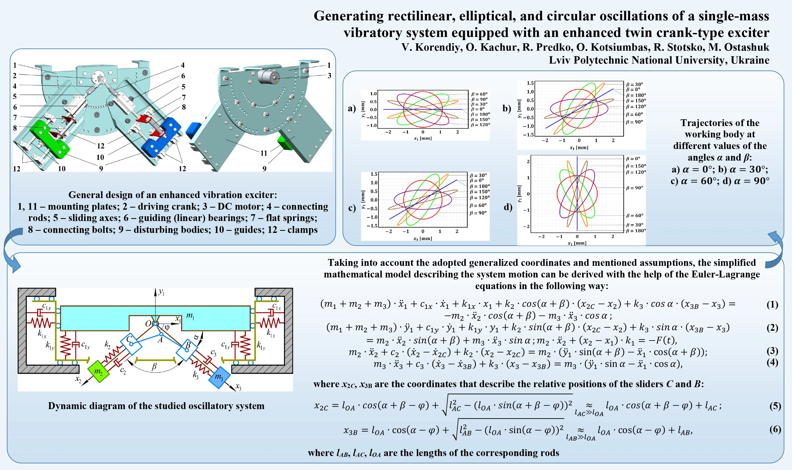
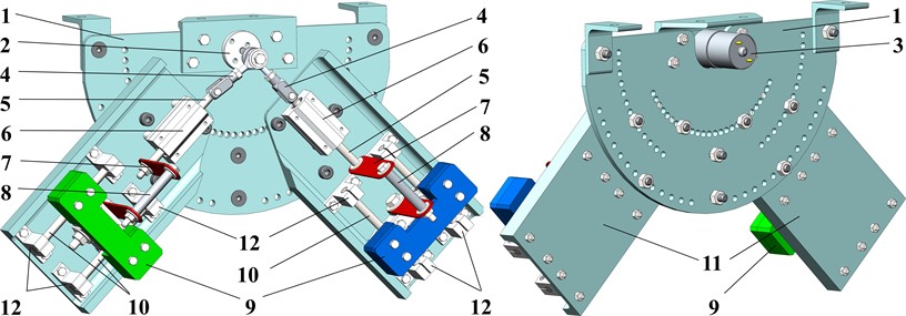
The general design of the developed vibration exciter is presented in Fig. 1. All the components are installed on the plate 1, which can be fixed to the machine’s body. The rotation of the crank 2 is generated by the DC motor 3. The connecting rods 4 transmit the motion to the sliding axes 5. The guiding (linear) bearings 6 are used for providing the rectilinear reciprocating motion of the axes 5. The set of two flat springs 7 connected by the bolt 8 is used for connecting the sliding axis 5 with the disturbing mass 9. The latter can reciprocate along the guides (guiding axes) 10, which are fixed to the plates 11 with the help of the clamps 12. Due to applying a system of holes on the plate 1, the angular position of the exciters (plates 11) can be adjusted, i.e., the direction of the reciprocating motion of the disturbing bodies 9 can be controlled. This allows for regulating the trajectory of the machine’s working member in accordance with the technological requirements.
Fig. 1General design of an enhanced vibration exciter: 1, 11 – mounting plates; 2 – driving crank; 3 – DC motor; 4 – connecting rods; 5 – sliding axes; 6 – guiding (linear) bearings; 7 – flat springs; 8 – connecting bolts; 9 – disturbing bodies; 10 – guides; 12 – clamps
2.2. Dynamic diagram and mathematical model of the oscillatory system
Let us consider the simplified dynamic diagram of the oscillatory system shown in Fig. 2. The working member (mass ) is suspended from the stationary (unmovable) base by the spring-damper elements, which are characterized by the horizontal and vertical stiffness and damping coefficients , , , and , respectively. The rotary motion and angular position of the driving crank are described by the angle , which is the function of time. The motion directions of the disturbing bodies (masses and ) are defined by the controllable (adjustable) angles and . The excitation mechanism consists of two spring-damper elements, which are installed between the sliders (, ) and disturbing bodies (masses and ) and are characterized by the stiffness and damping coefficients , , , and , respectively. The sliders are set into motion by the connecting rods (, ) hinged to the crank at and joined with the sliders by the hinges and , respectively. In order to uniquely describe the system motion, the following generalized coordinates can be adopted: horizontal and vertical displacements of the working member (mass ) from its equilibrium position – and ; angular position of the driving crank with respect to the rightward directed horizontal axis – ; relative displacements of the disturbing bodies along the corresponding guiding axes with respect to their equilibrium positions – and .
Fig. 2Dynamic diagram of the studied oscillatory system
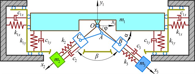
While performing further investigations, the following assumptions have been adopted: the dry friction forces occurring during the elements motion are neglected; the angular oscillations of the working member are restricted; the motor provides the constant angular speed (rotation frequency) of the driving crank . The latter allows for defining the angular position of the crank at each time moment as follows: . Taking into account the adopted generalized coordinates and mentioned assumptions, the simplified mathematical model describing the system motion can be derived with the help of the Euler-Lagrange equations in the following way:
where , are the coordinates that describe the relative positions of the sliders and :
where , , are the lengths of the corresponding rods (see Fig. 2).
2.3. Substantiating the system parameters
Considering the necessity of providing the near resonance operational conditions of the disturbing bodies (in order to improve the machine’s performance) and non-resonant (far-over-resonance) vibrations of the working member (taking into account the possible overloading), the following expressions can be used for calculating the system’s stiffness parameters:
where , are the reduced masses of the system; , , , are the correction coefficients .
3. Results and discussion
In order to carry out further numerical modeling of the considered vibratory system motion, let us define its main geometrical, inertial, stiffness, damping, and operational parameters (particularly, based on the vibration exciter design developed in the SolidWorks software (see Fig. 1) and on similar designs of the vibratory technological machines considered in [15]-[17]): 30 kg, 1 kg, 0.015 m, 0.08 m, 104.7 rad/s (i.e., the DC motor shaft rotates at the constant forced frequency of 1000 rpm), 100 (N∙s)/m, 50 (N∙s)/m, 45.4 kN/m, 10.8 kN/m. The angles and are the controllable parameters influencing the working member trajectory to be studied.
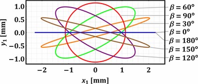
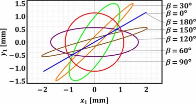
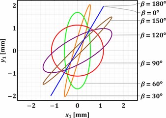
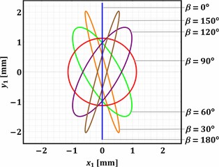
Substituting the presented above values of the input parameters into the previously derived system of the differential Eq. (1-4), and considering the zero initial conditions (state of rest: ), the Runge-Kutta methods integrated into the Mathematica software were used to numerically find the parametric solutions , , (with the changeable parameters and ). The “ExplicitRungeKutta” function allows for the numerical solving of stiff and quasi-stiff systems using the proportional-integral step-size controller. At the same time, the “ParametricNDSolve” function solves the systems of ordinary differential equations for the time functions of the generalized coordinates in the given range (e.g., 0…2 s) taking into account the changeable parameters (angles and ) that influence the dynamic behavior of the considered mechanical system. The numerically obtained plots shown in Fig. 3 illustrate the trajectories (paths) of the working member (mass m1) vibrations at different values of the angles and : 0°, 30°, 60°, 90°, 0°, 30°, 60°, 90°, 120°, 150°, 180°.
Analyzing the results of numerical modeling presented in Fig. 3, the following conclusions can be drawn. The change in the angle allows for regulating the trajectory of the working member vibrations. The rectilinear oscillations are observed at 0° and 180°, while the circular trajectory is described at 90°. All the other values of the angle cause the generation of elliptical vibrations characterized by different ellipse shapes (eccentricity, focal distance, ratio between the minor and major axes, etc.). The direction of the rectilinear oscillations and the angular positions of the ellipse major axes depends on the angle . The horizontal rectilinear vibrations are observed at 0° (may be used for sieving different loose and bulky products), while the vertical ones take place at 90° (may be used during the compaction of materials).
The angular position of the major axis of the elliptical trajectory defines the conveying direction of the products placed on the working member. Considering the case when 0° (Fig. 3(a)), the rightward conveying can be observed at the angles 0… 90°, while the leftward one is provided at 90… 180°. In distinction to the previous case, Fig. 3(d) shows that the angle 90° causes the opposite conveying directions at the same angles . At 30° (Fig. 3(b)) and 60° (Fig. 3(c)), the rectilinear oscillations and the corresponding major axes of the elliptical paths are counter-clockwise (anti-clockwise) inclined at 30° and 60° relative to their initial positions at 0°. Therefore, the implementation of the proposed twin crank-type exciter allows for adjusting the vibration trajectory of the working member in accordance with the technological requirements depending on the operation to be provided (conveying, screening, sieving, compacting, etc.) and the physical-mechanical properties of the products to be treated.
Fig. 3Trajectories of the working body at different values of the angles α and β: a) α=0°; b) α=30°; c) α=60°; d) α=90°
a)
b)
c)
d)
4. Conclusions
The paper presents the authors’ recent research results dedicated to the development and practical implementation of the enhanced twin crank-type exciter for actuating various vibratory technological equipment. The proposed exciter is driven by a DC motor allowing for a relatively easy regulation of the forced frequency. On the other hand, the possibilities of adjusting the working member’s kinematic and dynamic parameters in accordance with the technological requirements are provided by applying the twin crank-slider mechanism with the controllable directions of the disturbing bodies reciprocation. The corresponding dynamic diagram of the single-mass vibratory system equipped with the proposed exciter is considered, and the mathematical model describing the system motion is derived using the Euler-Lagrange equations. The numerical simulation is performed in the Mathematica software with the help of the Runge-Kutta methods. The obtained results are presented in the form of trajectories (paths) of the working member vibrations at different angles of the sliders’ reciprocation directions.
The analysis of the plots presented in Fig. 3 substantiates that the proposed twin crank-type excitation mechanism allows for adjusting the vibration trajectory of the working member in accordance with the technological requirements depending on the operation to be provided (conveying, screening, sieving, compacting, etc.) and the physical-mechanical properties of the products to be treated. The rectilinear oscillations are observed at 0° and 180°, while the circular trajectory is described at 90°. All the other values of the angle cause the generation of elliptical vibrations. Further investigations on the subject of this research can be focused on determining the dynamic and power characteristics of the proposed exciter, as well as on designing the adaptive control system for ensuring the possibility of real-time adjusting of the exciter’s parameters in accordance with the changeable operational and technological conditions.
References
-
S. Kilikevičius, K. Liutkauskienė, R. Česnavičius, A. Keršys, and R. Makaras, “Investigation of the motion characteristics of parts on a platform subjected to planar oscillations,” Applied Sciences, Vol. 13, No. 17, p. 9576, Aug. 2023, https://doi.org/10.3390/app13179576
-
D. Lin et al., “A rigid-flexible coupled dynamic model of a flip-flow vibrating screen considering the effects of processed materials,” Powder Technology, Vol. 427, p. 118753, Sep. 2023, https://doi.org/10.1016/j.powtec.2023.118753
-
P. Krot, H. Shiri, P. Dąbek, and R. Zimroz, “Diagnostics of bolted joints in vibrating screens based on a multi-body dynamical model,” Materials, Vol. 16, No. 17, p. 5794, Aug. 2023, https://doi.org/10.3390/ma16175794
-
R. Geng, C. Yu, Y. Wang, X. Wang, X. Zhang, and R. Li, “Effect of external moisture content on screening performance of vibrating flip-flow screen and circular vibrating screen,” Minerals, Vol. 13, No. 5, p. 585, Apr. 2023, https://doi.org/10.3390/min13050585
-
Y. Kharchenko et al., “Nanostructural changes in a Ni/NiO cermet during high-temperature reduction and reoxidation,” Springer Proceedings in Physics, Vol. 246, pp. 219–229, 2021, https://doi.org/10.1007/978-3-030-51905-6_17
-
V. P. Vellingiri and U. Sadasivam, “Effect of vibrator parameters and physical characteristics of parts on conveying velocity,” Strojniški vestnik – Journal of Mechanical Engineering, Vol. 69, No. 7-8, pp. 352–363, Jun. 2023, https://doi.org/10.5545/sv-jme.2022.510
-
G. Cieplok, “Self-synchronization of drive vibrators of an antiresonance vibratory conveyor,” Journal of Theoretical and Applied Mechanics, Vol. 61, No. 4, pp. 501–511, Oct. 2023, https://doi.org/10.15632/jtam-pl/170840
-
V. Gurskyi, V. Korendiy, P. Krot, R. Zimroz, O. Kachur, and N. Maherus, “On the dynamics of an enhanced coaxial inertial exciter for vibratory machines,” Machines, Vol. 11, No. 1, p. 97, Jan. 2023, https://doi.org/10.3390/machines11010097
-
V. Korendiy, I. Kuzio, S. Nikipchuk, O. Kotsiumbas, and P. Dmyterko, “On the dynamic behavior of an asymmetric self-regulated planetary-type vibration exciter,” Vibroengineering Procedia, Vol. 42, pp. 7–13, May 2022, https://doi.org/10.21595/vp.2022.22580
-
V. Korendiy, V. Gurey, V. Borovets, O. Kotsiumbas, and V. Lozynskyy, “Generating various motion paths of single-mass vibratory system equipped with symmetric planetary-type vibration exciter,” Vibroengineering Procedia, Vol. 43, pp. 7–13, Jun. 2022, https://doi.org/10.21595/vp.2022.22703
-
G. F. Alışverişçi, “The nonlinear behavior of vibrational conveyers with single-mass crank-and-rod exciters,” Mathematical Problems in Engineering, Vol. 2012, pp. 1–17, 2012, https://doi.org/10.1155/2012/534189
-
V. V. Mikheyev, “New type of vibration generator with vibratory force oriented in preferred direction,” Journal of Vibration Engineering and Technologies, Vol. 6, No. 2, pp. 149–154, Apr. 2018, https://doi.org/10.1007/s42417-018-0025-4
-
A. Kim, M. Doudkin, A. Ermilov, G. Kustarev, M. Sakimov, and M. Mlynczak, “Analysis of vibroexciters working process of the improved efficiency for ice breaking, construction and road machines,” Journal of Vibroengineering, Vol. 22, No. 3, pp. 465–485, May 2020, https://doi.org/10.21595/jve.2020.20446
-
A. Sinha, S. K. Bharti, A. K. Samantaray, G. Chakraborty, and R. Bhattacharyya, “Sommerfeld effect in an oscillator with a reciprocating mass,” Nonlinear Dynamics, Vol. 93, No. 3, pp. 1719–1739, Aug. 2018, https://doi.org/10.1007/s11071-018-4287-x
-
O. Lanets, O. Kachur, V. Korendiy, and V. Lozynskyy, “Controllable crank mechanism for exciting oscillations of vibratory equipment,” in Lecture Notes in Mechanical Engineering, pp. 43–52, 2021, https://doi.org/10.1007/978-3-030-77823-1_5
-
V. Korendiy, O. Kachur, and P. Dmyterko, “Kinematic analysis of an oscillatory system of a shaking conveyor-separator,” in Lecture Notes in Mechanical Engineering, pp. 592–601, 2022, https://doi.org/10.1007/978-3-030-91327-4_57
-
V. Korendiy, V. Gursky, O. Kachur, P. Dmyterko, O. Kotsiumbas, and O. Havrylchenko, “Mathematical model and motion analysis of a wheeled vibro-impact locomotion system,” Vibroengineering Procedia, Vol. 41, pp. 77–83, Apr. 2022, https://doi.org/10.21595/vp.2022.22422
Cited by
About this article

The authors have not disclosed any funding.
The datasets generated during and/or analyzed during the current study are available from the corresponding author on reasonable request.
The authors declare that they have no conflict of interest.
