Abstract
Vibration-driven locomotion systems are widely used in various industries, particularly, in the form of capsule-type robots, wheeled platforms, worm-like units, etc. Because of the changeable operating conditions, such systems require continuous control of their kinematic and dynamic characteristics. The main purpose of the present paper is to define the optimal excitation conditions (forced frequencies and phase shifts) of a wheeled two-module vibration-driven robot equipped with two unbalanced rotors. The research methodology contains four stages: developing the robot’s dynamic diagram and mathematical model describing its motion; designing the robot’s simulation model in the MapleSim software; numerical modeling of the system locomotion conditions in the Mathematica software; simulating the system dynamic behavior in the MapleSim software. The obtained results show the time dependencies of the system’s kinematic characteristics at different phase shift angles of the unbalanced rotors. The major scientific novelty of this paper consists in substantiating the possibilities of adjusting the system’s operational parameters in accordance with the changeable technological requirements by means of changing the phase shift angles of the unbalanced rotors. The proposed ideas and obtained results can be used while developing new designs of robots based on the two-module vibration-driven systems and while improving the control systems for adjusting their performance in accordance with the changeable operational conditions.
Highlights
- The dynamic diagram of the wheeled two-module vibration-driven robot equipped with two unbalanced rotors is developed and the mathematical model describing its motion is derived.
- In order to provide the system’s near-resonance operational conditions, the mathematical dependencies for determining the corresponding forced frequency and spring stiffness are deduced.
- The numerical modeling of the system locomotion conditions is carried out in the Mathematica software, and the virtual experiments (computer simulation) are conducted in the MapleSim software.
- The obtained results may be used while developing new designs of robots based on two-module vibration-driven locomotion systems with two unbalanced rotors and while improving their control systems.
1. Introduction
Vibration-driven systems are widely used for actuating various mobile machines in different industries, particularly, in the medicine and healthcare sector [1, 2], mining, road- and house-building, oil and gas industries, etc. In a vast majority of vibration-driven machines, the stick-slip locomotion conditions are implemented. The dynamic behavior of a vibro-impact capsule-type system equipped with a delayed feedback controller is thoroughly studied in [1]. The peculiarities of implementing this system while performing the colonoscopy are theoretically and experimentally investigated in [2]. The paper [3] considers an improved double-crank vibration exciter based on a twin crank-slider mechanism and used for actuating the sliding locomotion of a platform. In [4], the authors studied the motion characteristics of a vibro-impact system under different operational conditions (friction levels, excitation force magnitudes, angles of inclination of the supporting surfaces, etc.). The paper [5] is focused on modeling the dynamics of a sliding platform actuated by a vibro-impact exciter equipped with double-sided elastic constraints and disturbed by a half-sine periodic force.
In distinction to the sliding locomotion systems mentioned above, wheeled vibration-driven robots are also widely studied. The interesting designs of the self-actuated locomotion systems equipped with synchronized centrifugal exciters and unidirectionally rotating wheels are proposed and investigated in [6, 7]. Similar research on the wheeled vibro-impact platforms with crank-type inertial exciters was performed in [8, 9, 10], where the authors carried out theoretical and experimental studies on the platform’s dynamic behavior under different design parameters (impact gap values, disturbing body and platform masses, springs stiffnesses, etc.) and operational conditions (forced frequencies, friction levels, etc.).
Another prospective design of mobile vibration-driven robots is based on multi-module locomotion systems, whose members are connected by spring-damper elements. The problems of maximizing the robot’s translational speed with simultaneous minimization of the power consumption are currently comprehensively studied, particularly, in [11, 12]. The papers [13, 14] are dedicated to analyzing the dynamic behavior and sliding bifurcations of a multi-module vibration-driven robot under different dry-friction conditions.
The present paper is based on the authors’ previous research published in [15, 16]. The peculiarities of implementing the centrifugal exciter for actuating the wheeled robot are studied in [15], while the sliding two-module system dynamics is analyzed in [16]. The main purpose of the present paper is to define the optimal excitation conditions (forced frequencies and phase shifts) of a wheeled two-module vibration-driven robot equipped with two unbalanced rotors.
2. Research methodology
2.1. Dynamic diagram and mathematical model of the vibration-driven locomotion system
Let us consider the wheeled two-module vibration-driven locomotion system, whose dynamic diagram is shown in Fig. 1. The system consists of two movable platforms, which can roll along a smooth horizontal surface. The platforms are connected by a spring-damper element characterized by stiffness and damping coefficient . To actuate the system, two inertial vibration exciters (unbalanced rotors) are mounted on each platform. The rotary motions of the rotors are described by the corresponding laws and , while the positions of the movable platforms relative to the inertial reference system are defined by the generalized coordinates and . The masses of the front and rear platforms are denoted as , , respectively, and the masses of the corresponding unbalanced rotors are , . In addition, the rotors are characterized by the eccentricities , .
Fig. 1Dynamic diagram of the wheeled two-module vibration-driven locomotion system

While performing further investigations, let us assume zero-friction conditions when the wheels are rolling along a smooth horizontal surface. Let us study the case of the steady-state operational conditions of the inertial exciters when the rotors’ angular speeds are constant and equal to and . Denoting the initial positions (phases of oscillations) of the front and rear unbalanced rotors as and their motion laws can be described as follows: , . The mathematical model describing the locomotion conditions of the considered wheeled two-module vibration-driven system with two unbalanced rotors can be derived using the Euler-Lagrange equations and presented in the following form:
where the dots above and denote the first- and second-order derivatives of these displacements with respect to time, i.e., the corresponding velocities and accelerations.
Taking into account the fact that the considered locomotion system is semidefinite, its first natural frequency equals zero, which shows that the platforms move (oscillate) as a single body. The second natural frequency of the two-mass vibratory system can be determined as follows:
Eq. (2) allows for determining the spring stiffness of the considered vibration-driven locomotion system providing its energy-efficient near-resonance operational conditions:
where is the correction coefficient providing the near-resonance operation.
Therefore, when the system’s inertial parameters (, , , ) are known, and the forced frequency is prescribed, the necessary natural frequency can be determined as follows: , where can take different values depending on a particular design and operational peculiarities of the system 0.93…0.99 [16]). Then, Eq. (3) can be used for calculating the necessary spring stiffness providing the system’s near-resonance locomotion.
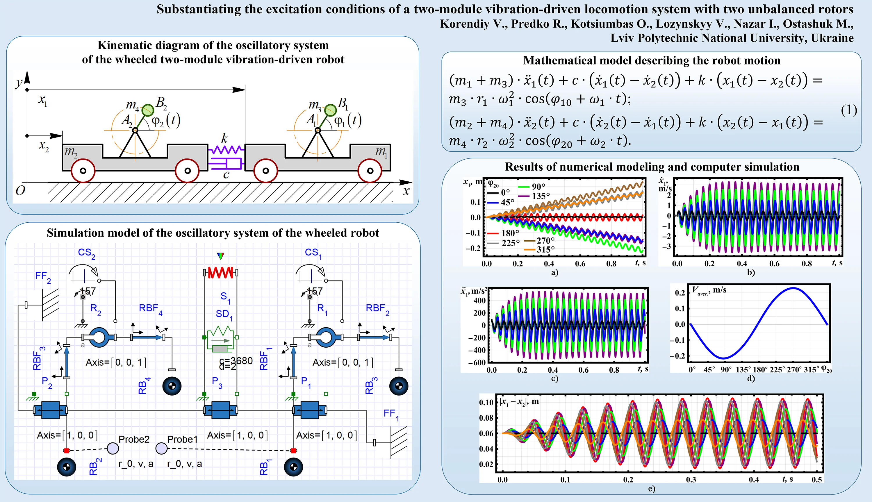
Fig. 2Simulation model of the two-module vibration-driven system developed in MapleSim software
2.2. Simulation model of the two-module vibration-driven system
The simplified simulation model of the two-module vibration-driven system is developed in the MapleSim software (Fig. 2). Two prismatic sliders P1 and P2 with the connected masses RB1 and RB2 are used for simulating the movable platforms. The rods RBF1, RBF2, RBF3, RBF4 with the revolute joints , and joined masses RB3, RB4 simulate the unbalanced rotors.
To actuate the unbalanced rotors, the corresponding constant-speed motion drivers (motors) CS1 and CS2 are used. The sliders P1 and P2 are connected by slider P3 equipped with the spring-damper elements SD1 and S1. The fixed frames FF1 and FF2 are used for prescribing the initial positions and motion directions of the sliders P1 and P2. To define the kinematic characteristics of the platforms (masses RB1, RB2), the corresponding sensors Probe1 and Probe2 are applied.
3. Results and discussion
3.1. Numerical modeling of the system locomotion in the Mathematica software
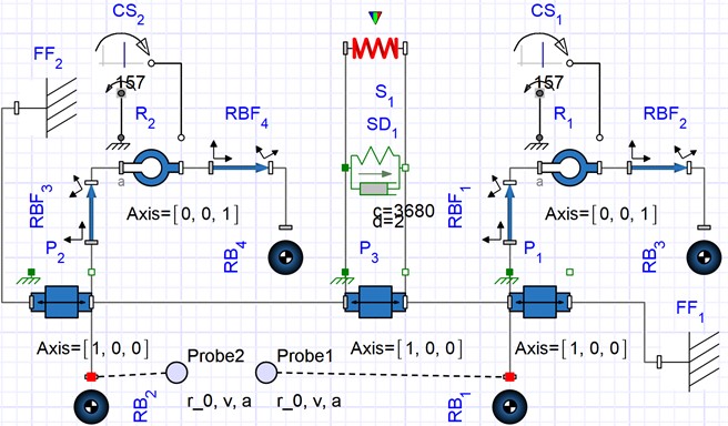
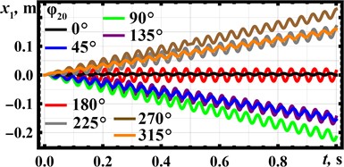
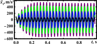
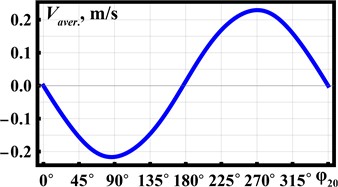
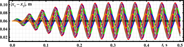
Let us analyze the system’s locomotion conditions in the Mathematica software by numerical solving of the system of differential Eq. (1) using the Runge-Kutta methods. The following inertial and excitation parameters are considered: 0.25 kg, 0.025 kg, 157 s-1, 2 (N∙s)/m, 0. Using the Eq. (3), the spring stiffness can be calculated: 3.7∙103 N/m. To perform further numerical modeling, the following values of the phase shift angle of the rear unbalanced rotor are adopted: 0, 45° (/4), 90° (/2), 135° (3/4), 180° (), 225° (5/4), 270° (3/2), 315° (7/4). The corresponding modeling results are shown in Fig. 3 using the black, blue, green, purple, red, gray, brown, and orange curves, respectively. Figs. 3(a-c) show time dependencies of the front platform’s basic kinematic characteristics (displacement, velocity, acceleration) at different phase shift angles . In Fig. 3(d), the dependence of the front platform’s average speed on is presented. Fig. 3(e) describes the relative positions (displacements) of the front and rear platforms in time. The initial distance between the platforms is set equal to 0.06 m.
The distance traveled by the front platform during the time period of 1 s, as well as the motion direction, significantly depends on the phase shift angle (see Fig. 3). The angles 45°, 90°, and 135° provide the backward motion, while at 225°, 270°, and 315° the platform moves forward. The largest average speeds of about 0.23 m/s are observed at 90° and 270°, while the lowest ones are equal to zero at 0° and 180°. The maximal instantaneous values of the platform’s speed and acceleration reach 3.7 m/s and 550 m/s2, respectively, at 135°. The maximal relative distance between the front and rear platforms exceeds 0.1 m, while the minimal one is about 0.015 m at 180°. The obtained results will be used while designing the experimental prototype of the wheeled vibration-driven robot.
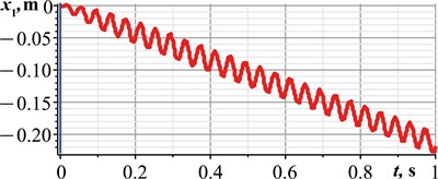
4. Simulation of the system dynamic behavior in the MapleSim software
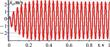
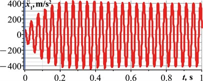
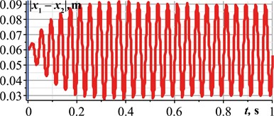
Let us carry out a computer simulation of the system locomotion in the MapleSim software in order to verify the correctness of the numerical modeling results obtained in the Mathematica software. While conducting virtual experiments, all inertial, stiffness, damping, and excitation parameters are similar to those mentioned above. Let us consider the case of the system’s best performance, when the phase shift angle 90°. The corresponding simulation results are shown in Fig. 4. Considering Fig. 4(a), the front platform moves in a backward direction and during the time period of 1 s passed a distance of about 0.23 m. This allows for concluding that its average translational speed is 0.23 m/s. At 90°, the maximal instantaneous values of the platform’s speed and acceleration exceed 2.8 m/s and 400 m/s2, respectively. The maximal relative distance between the front and rear platforms is approximately 0.09 m, while the minimal one reaches 0.03 m. In general, all the obtained simulation results satisfactorily agree with the corresponding numerical modeling results shown by the green curves in Figs. 3(a-c, e).
Fig. 3Numerically modeled kinematic characteristics of the vibration-driven locomotion system
a)
b)
c)
d)
e)
Fig. 4Results of virtual experiments carried out in the MapleSim software
a)
b)
c)
d)
5. Conclusions
The research is focused on analyzing the dynamic behavior of the wheeled two-module vibration-driven locomotion system equipped with two unbalanced rotors under different excitation parameters. The system’s near-resonance operational conditions are substantiated by applying the corresponding forced frequency and spring stiffness. The phase shift angle of the rear unbalanced rotor is chosen as the controllable parameter providing the change in the system’s kinematic characteristics and motion direction. The corresponding dynamic diagram and simulation model of the wheeled vibration-driven locomotion system are considered, and the differential equations describing its motion are derived. The numerical modeling of the system locomotion conditions is carried out in the Mathematica software, and the virtual experiments (computer simulation) are conducted in the MapleSim software. The results show that the angle of 45°, 90°, and 135° provides the system’s backward motion, while at 225°, 270°, and 315° the platform moves in forward direction. The largest average speeds of about 0.23 m/s are observed at 90° and 270°, while the lowest ones are equal to zero at 0° and 180°. The maximal relative distance between the front and rear platforms exceeds 0.1 m, while the minimal one is about 0.015 m at 180°. The obtained results may be used while developing new designs of robots based on the two-module vibration-driven locomotion systems with two unbalanced rotors and while improving their control systems.
References
-
Z. Zhang, J. Páez Chávez, J. Sieber, and Y. Liu, “Numerical analysis of a multistable capsule system under the delayed feedback control with a constant delay,” International Journal of Non-Linear Mechanics, Vol. 152, p. 104390, Jun. 2023, https://doi.org/10.1016/j.ijnonlinmec.2023.104390
-
J. Zhang, Y. Liu, J. Tian, D. Zhu, and S. Prasad, “Design and experimental investigation of a vibro-impact capsule robot for colonoscopy,” IEEE Robotics and Automation Letters, Vol. 8, No. 3, pp. 1842–1849, Mar. 2023, https://doi.org/10.1109/lra.2023.3243804
-
V. Korendiy, V. Gursky, O. Kachur, V. Gurey, O. Havrylchenko, and O. Kotsiumbas, “Mathematical modeling of forced oscillations of semidefinite vibro-impact system sliding along rough horizontal surface,” Vibroengineering Procedia, Vol. 39, pp. 164–169, Dec. 2021, https://doi.org/10.21595/vp.2021.22298
-
T.-H. Duong et al., “Dynamic response of vibro-impact capsule moving on the inclined track and stochastic slope,” Meccanica, Vol. 58, No. 2-3, pp. 421–439, Mar. 2023, https://doi.org/10.1007/s11012-022-01521-9
-
K.-T. N. Khac-Tuan Nguyen et al., “Modelling of a vibration-driven module for capsule locomotion systems,” International Journal of Mechanical and Production Engineering Research and Development, Vol. 10, No. 3, pp. 837–850, 2020, https://doi.org/10.24247/ijmperdjun202075
-
I. A. Loukanov, V. G. Vitliemov, and I. V. Ivanov, “Dynamics of a mobile mechanical system with vibration propulsion (VibroBot),” International Journal of Research in Engineering and Science, Vol. 4, No. 6, pp. 44–51, 2016.
-
I. A. Loukanov, V. G. Vitliemov, and I. V. Ivanov, “Dynamics of a vibration-driven one-way moving wheeled robot,” IOSR Journal of Mechanical and Civil Engineering, Vol. 13, No. 3, pp. 14–22, 2016, https://doi.org/10.9790/1684-1303051422
-
V. Korendiy et al., “Motion simulation and impact gap verification of a wheeled vibration-driven robot for pipelines inspection,” Vibroengineering Procedia, Vol. 41, pp. 1–6, Apr. 2022, https://doi.org/10.21595/vp.2022.22521
-
V. Korendiy, V. Gursky, O. Kachur, P. Dmyterko, O. Kotsiumbas, and O. Havrylchenko, “Mathematical model and motion analysis of a wheeled vibro-impact locomotion system,” Vibroengineering Procedia, Vol. 41, pp. 77–83, Apr. 2022, https://doi.org/10.21595/vp.2022.22422
-
V. Korendiy, O. Kachur, V. Gurskyi, and P. Krot, “Studying the influence of the impact gap value on the average translational speed of the wheeled vibration-driven robot,” Engineering Proceedings, Vol. 24, No. 1, p. 25, Sep. 2022, https://doi.org/10.3390/iecma2022-12897
-
B. Diao, X. Zhang, H. Fang, and J. Xu, “Optimal control of the multi-module vibration-driven locomotion robot,” Journal of Sound and Vibration, Vol. 527, p. 116867, Jun. 2022, https://doi.org/10.1016/j.jsv.2022.116867
-
B. Diao, X. Zhang, H. Fang, and J. Xu, “Bi-objective optimization for improving the locomotion performance of the vibration-driven robot,” Archive of Applied Mechanics, Vol. 91, No. 5, pp. 2073–2088, May 2021, https://doi.org/10.1007/s00419-020-01870-5
-
Y. Zhao, H. Fang, B. Diao, X. Zhang, and J. Xu, “Exploiting the bistable dynamics in a two-module vibration-driven robot for locomotion performance enhancement,” Journal of Sound and Vibration, Vol. 544, p. 117387, Feb. 2023, https://doi.org/10.1016/j.jsv.2022.117387
-
H. Fang, Y. Zhao, and J. Xu, “Steady-state dynamics and discontinuity-induced sliding bifurcation of a multi-module piecewise-smooth vibration-driven system with dry friction,” Communications in Nonlinear Science and Numerical Simulation, Vol. 114, p. 106704, Nov. 2022, https://doi.org/10.1016/j.cnsns.2022.106704
-
V. Korendiy, O. Kachur, V. Gurey, I. Kuzio, T. Hurey, and O. Havrylchenko, “Dynamics of a wheeled robot driven by an unbalanced rotor and equipped with the overrunning clutches,” Vibroengineering Procedia, Vol. 48, pp. 1–7, Feb. 2023, https://doi.org/10.21595/vp.2022.23103
-
V. Korendiy, “Substantiation of parameters and motion modelling of two-mass mobile vibratory system with two unbalanced vibration exciters,” Avtomatizacìâ Virobničih Procesìv U Mašinobuduvannì Ta Priladobuduvannì, Vol. 52, pp. 16–31, 2018, https://doi.org/10.23939/istcipa2018.52.016
About this article

The authors have not disclosed any funding.
The datasets generated during and/or analyzed during the current study are available from the corresponding author on reasonable request.
The authors declare that they have no conflict of interest.
