Abstract
The in-pipe robots are currently of significant interest, considering numerous recent publications on this subject. Such machines can use various locomotion principles: wheeled, tracked (caterpillar), walking (legged), screw-type, worm-type, snake-type, etc. In most cases, such robots are equipped with an active drive system transmitting the torque from a motor shaft to the corresponding locomotion mechanism (wheels, tracks, etc.). The present paper is devoted to the wheeled in-pipe robot that doesn’t need a complex transmission. In such a case, the idea of implementing the vibratory locomotion system driven by an internal unbalanced mass is proposed. The corresponding kinematic diagram of the wheeled vibration-driven in-pipe robot is developed, and the differential equations describing the robot motion are deduced. In order to carry out the virtual experimental investigations, the robot’s simulation model is designed in the SolidWorks software. The major scientific novelty of the present research consists in developing the theoretical foundation for designing and practical implementation of the in-pipe robots driven by the inertial vibration exciters and equipped with the unidirectionally rotating wheels and overrunning clutches. The results of numerical modeling and computer simulation of the robot motion substantiate the possibilities and expediency of implementing the proposed vibration-driven locomotion principles while creating novel designs of the in-pipe robots.
Highlights
- The novel in-pipe robot is proposed, whose rear wheels are equipped with the overrunning (free-wheel) clutches and the vibrations are generated by the inertial exciter (rotating unbalanced mass).
- The corresponding kinematic diagram of the robot’s oscillatory system is developed and the mathematical model describing the robot locomotion conditions is derived.
- The numerical modeling and computer simulation of the robot operation are conducted. The obtained results showed that the robot average speed is about 1.7…1.8 m/s at the forced frequency of 15 Hz.
1. Introduction
The in-pipe robots are widely used for carrying out the inspecting, cleaning, repairing, welding, and other technological operations inside the pipelines. The main characteristic feature of such robots is the type of the locomotion mechanism. Numerous investigations are dedicated to various locomotion principles of in-pipe robots. For example, the recent papers [1] and [2] present a comprehensive analysis of the design and operational peculiarities of the in-pipe robots. Among a great variety of locomotion mechanisms, particularly wheeled, tracked (caterpillar), walking (legged), screw-type, inchworm-type, snake-type, etc., the wheeled ones are of the most widespread. In order to provide the adaptation of the wheeled traction systems to a certain pipe’s diameter, the corresponding controlling mechanisms are used. The paper [3] considers a wide range of linkages used for changing the geometrical parameters of the wheeled in-pipe robots. In addition, such linkages provide the sufficient contact forces between the driving wheels and the inner surface of the pipe in which the robot is working.
In order to set the in-pipe robot into motion, various drives are used. For example, the paper [4] considers the pneumatically-operated vibration-driven robot equipped with the sprung sliding and rolling supports ensuring its unidirectional motion. In [5], the authors proposed a novel design of the wheeled screw-type in-pipe robot driven by a single electric motor providing the robot rectilinear motion along the pipeline. The inchworm locomotion principle provided by the improved self-locking mechanism has been implemented in the hydraulically-operated in-pipe robot presented in [6]. The screw-type wheeled robot with the complex electromechanical transmission providing the controllable motion of the robot’s wheeled frames is studied in [7]. The paper [8] presents the improved in-pipe robot equipped with two mechanically synchronized mechanisms: cam-linkage and sliding-rotating ones, which are driven by one electric motor and provide the inchworm-type locomotion principle. A novel design of the pipe-inspection robot with two unidirectionally sliding frames and six slider-crank-type mechanisms actuating the telescopic supporting elements is considered in [9]. The paper [10] is focused on defining the optimal sliding modes of the electromagnetically driven worm-like robot.
Analyzing numerous publications on the subject of in-pipe robots, e.g., [1]-[10], it can be concluded that most robots are equipped with an active drive system transmitting the torque from the driving unit to the corresponding locomotion mechanism (wheels, tracks, etc.). Taking into account the complexity of such transmissions, some researchers analyze the possibilities of implementing the passive locomotion principles based on vibration excitation. For example, the paper [11] considers the dynamic behavior of the small mobile vibration-driven robot equipped with the inertial (eccentric) exciter and flexible supporting bristles. In [12], the authors investigate the double-mass vibratory system of the in-pipe robot actuated by two inertial vibration exciters with a non-circular gear drive. Similar locomotion principles have been implemented in the improved vibratory compactor, which can slide along a rough surface and is equipped with the crank-type vibration exciter [13]. In [14], the authors proposed the enhanced inertial vibration exciter equipped with two synchronized and coaxially rotating unbalanced masses. The paper [15] is focused on studying the locomotion conditions of the wheeled vibration-driven robot with the double-mass oscillatory system and crank-type exciter.
The present paper continues the authors’ previous investigations on the vibration-driven systems, particularly [13]-[15], and considers the idea of implementing the wheeled vibratory in-pipe robot driven by an internal unbalanced mass. The major scientific novelty of the following investigations consists in developing the theoretical foundation for designing and practical implementation of the in-pipe robots driven by the inertial vibration exciters and equipped with the unidirectionally rotating wheels and overrunning (free-wheel) clutches.
2. Research methodology
2.1. Kinematic diagram and simulation model of the vibration-driven in-pipe robot
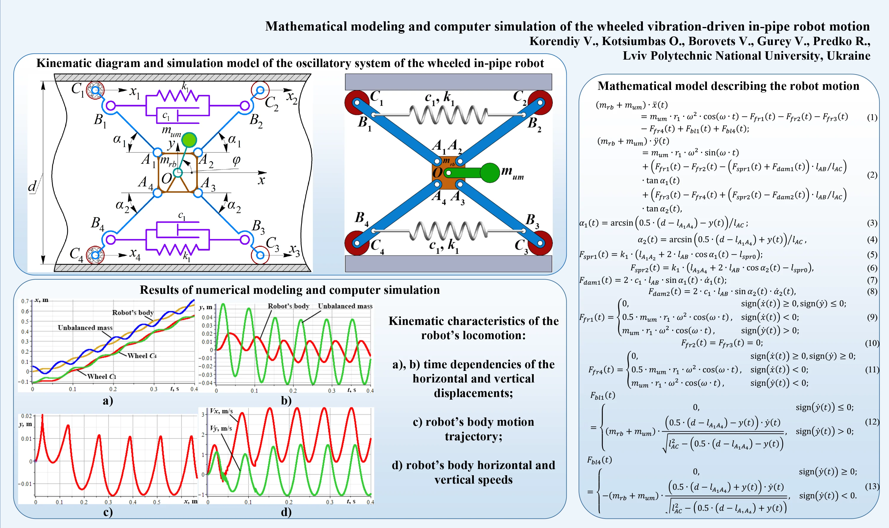
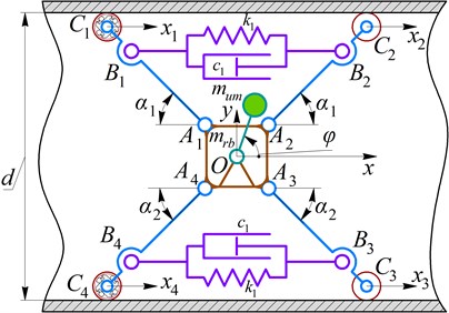
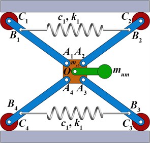
The major idea of this research consists in improving the wheeled in-pipe robot by means of implementing the vibratory locomotion system driven by an internal unbalanced mass (see Fig. 1). The robot’s wheels are pressed to the pipe’s walls with the help of the spring couplers.
The rear wheels are connected with the pressing levers using the overrunning (free-wheel) clutches (, ), whilst the front wheels are mounted with the help of the ball bearings (simple revolute joints, hinges , ). The clutches restrict the backward motion of the rear wheels. Herewith, the front wheels can rotate in any direction.
Let us consider the case when the robot’s body performs the plane-parallel motion due to the action of the inertial (centrifugal) forces generated due to the uniform rotation of the unbalanced mass . The forces are applied to the hinge simulating the motor’s shaft and locating at the body’s mass center (see Fig. 1). The considered vibratory locomotion system is characterized by two degrees of freedom. Adopting the inertial coordinate system at the initial equilibrium position of the body’s mass center, the corresponding generalized coordinates , allow for unambiguous describing the positions of all the system’s members at any time moment. The additional coordinates , , , will be used for analyzing the translational motion of the robot’s wheels. The proposed structure of the robot’s vibratory system allows for its easy adaptation to the changing internal diameter of the pipeline, and improves the possibilities of the robot operation inside the curved pipelines.
The rotary motion of the unbalanced mass is described by the controllable angular coordinate . The wheel can rotate in the clockwise direction, whilst its counterclockwise rotation is restricted by the overrunning (free-wheel) clutch. At the same time, the wheel can only rotate in the counterclockwise direction. Therefore, in the proposed design of the in-pipe robot, there is no need to use the complex active transmission.
Fig. 1Kinematic diagram and simulation model of the oscillatory system of the wheeled in-pipe robot
2.2. Mathematical model describing the robot motion
Let us consider the robot’s body as a particle of the mass located at the hinge , and the unbalanced mass rotating around the hinge at the radius . The geometrical parameters of the robot are adopted to be symmetrical, i.e.: , , , (see Fig. 1). The distances between the hinge O and the joints , , , () are assumed to be significantly smaller than all the other geometrical parameters, therefore the angular oscillations (turning) of the robot body are neglected. The clutches and bearings are located at the corresponding hinges , , , . Due to the fact that the masses of all the other bodies (e.g., the wheels with clutches and bearings, the pressing levers, etc.) are negligibly smaller than the robot’s body mass, let us derive the mathematical model describing the robot plane-parallel motion using the Lagrange-d’Alembert principle. Following two nonlinear differential equations describe the motion of the robot’s body:
where , are the radius (eccentricity) and angular velocity of the unbalanced mass rotation, respectively; , , , are the friction forces acting upon the robot’s wheels; , are the blocking forces taking place due to action of the overrunning (free-wheel) clutches; , are the restoring forces generated by the upper and lower springs during their tension; , are the damping forces generated by the upper and lower dampers; , denote the lengths of the corresponding rods. The angles , are marked in Fig. 1. It is necessary to mention that the friction, blocking, restoring, and damping forces, as well as the angles , are the functions of time.
To perform further calculations, let us derive the analytical expressions for , :
where is the internal (inside) diameter of the pipeline; denotes the distance between the corresponding hinges (see Fig. 1).
The time dependencies of the restoring forces can be described as follows:
where , are the distances between the corresponding hinges. It has been assumed that ; denotes the free length of the springs; is the springs stiffness.
The functions of the damping forces , are following:
where denotes the viscous friction coefficient of the damping element.
One of the most complicated tasks of the present research consists in predicting the time dependences and deriving the analytical expressions for the friction forces. In order to simplify further modeling process, let us assume the frictionless forward (rightward) motion of the robot, and consider the single-direction (one-way) rotation of the first and fourth wheels. In such a case, the time functions of the friction and blocking forces can be expressed as follows:
3. Results and discussion
3.1. Numerical modeling of the robot motion inside a horizontal pipeline
Substituting the derived Eqs. (3)-(13) into the system of differential Eqs. (1) and (2), the motion of the robot’s body can be mathematically modeled. Due to the significant complexity of the derived system, it is decided to carry out the numerical modeling of the robot motion using the applied software Wolfram Mathematica.
Using the robot’s simulation model (3D design) developed in the SolidWorks software (see Fig. 1), let us define its inertial and geometrical parameters: 0.095 m, 0.12 m, 0.028 m, 0.028 m, 0.022 m, 0.17 m, 0.05 m, 0.15 kg, 0.06 kg. The damping (viscous friction) coefficient 5 N∙s/m. The stiffness coefficient is following 70 N/m. The forced frequency is equal to 15 Hz and hence the angular velocity of the unbalanced mass 94 rad/s.
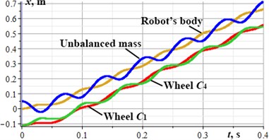
The results of numerical modeling of the robot motion inside a horizontal pipeline are presented in Fig. 2. During the modeling time (0.4 s) the robot has passed the distance of 0.65 m. The amplitude of the robot’s body vertical oscillations is about 0.012 m. The corresponding trajectory is presented in Fig. 2(c). The peak values of the robot’s horizontal and vertical speeds are equal to 3.3 m/s and 1.4 m/s, respectively. The average horizontal speed is about 1.7 m/s.
Fig. 2Kinematic characteristics of the robot’s locomotion: a), b) time dependencies of the horizontal and vertical displacements; c) robot’s body motion trajectory; d) robot’s body horizontal and vertical speeds
a)
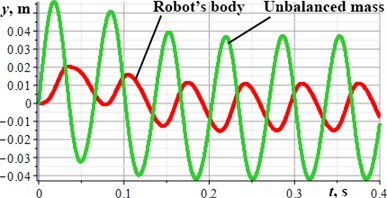
b)
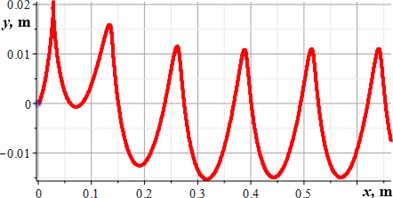
c)
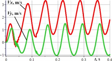
d)
3.2. Computer simulation of the robot motion
In order to verify the correctness of the numerical modeling results, the computer simulation (virtual experiment) of the robot motion has been carried out in the SolidWorks Motion software. Fig. 3 presents the basic stages of the robot locomotion. The initial position of the robot is shown on the left side. During the first stage, the robot’s body moves upward and rightward due to the action of the centrifugal forces generated by the unbalanced mass rotation. The upper left wheel becomes blocked, whilst the lower left one moves to the right. The next stage starts when the centrifugal force is directed to the left. The lower left wheel becomes blocked, and the upper left one moves to the right. When the unbalanced mass reaches its lowest position, the last locomotion stage starts, and both upper and lower left wheels move to the right.
Fig. 3Basic stages of the robot locomotion simulated with the help of the SolidWorks software
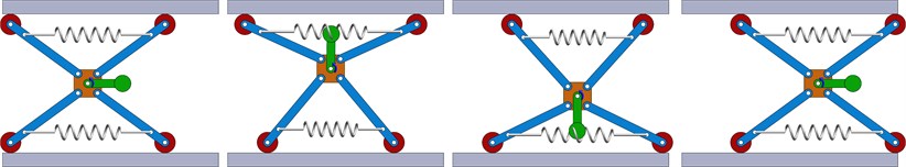
At the end of the first locomotion cycle, the robot’s body reaches the position similar to the initial one. The average horizontal displacement of the robot’s body during one cycle is about 0.12 m. This value allows for drawing the conclusion about the robot average horizontal speed equal to 0.18 m/s at the forced frequency of 15 Hz. Therefore, the results of virtual experiments satisfactorily agree with the results of numerical modeling.
4. Conclusions
The present research is focused on studying the dynamic behavior and motion characteristics of the wheeled vibration-driven robot for pipelines inspection. It is considered to equip the rear (left) wheels with the overrunning (free-wheel) clutches and generate the forced vibrations with the help of the inertial exciter (rotating unbalanced mass). The corresponding mathematical model of the robot’s oscillatory system is derived and the numerical modeling is carried out in the Mathematica software. The results of numerical modeling and computer simulation in the SolidWorks software showed that the robot average horizontal speed is about 1.7-1.8 m/s at the forced frequency of 15 Hz, i.e., when the angular velocity of the unbalanced mass is equal to 94 rad/s. The peak-to-peak value of the robot’s body vertical displacement is about 0.24 m, and the average displacement during one locomotion cycle is 0.12 m. The proposed vibration-driven locomotion principles can be implemented while creating novel designs of the in-pipe robots.
References
-
A. Verma, A. Kaiwart, N. D. Dubey, F. Naseer, and S. Pradhan, “A review on various types of in-pipe inspection robot,” Materials Today: Proceedings, Vol. 50, pp. 1425–1434, 2022, https://doi.org/10.1016/j.matpr.2021.08.335
-
H. Jang et al., “A review: technological trends and development direction of pipeline robot systems,” Journal of Intelligent and Robotic Systems, Vol. 105, No. 3, pp. 1–20, Jul. 2022, https://doi.org/10.1007/s10846-022-01669-2
-
C. Rusu and M. O. Tatar, “Adapting mechanisms for in-pipe inspection robots: a review,” Applied Sciences, Vol. 12, No. 12, p. 6191, Jun. 2022, https://doi.org/10.3390/app12126191
-
K. Ragulskis, M. Bogdevičius, and V. Mištinas, “Behaviour of dynamic processes in self-exciting vibration of a pipe robot,” Journal of Vibroengineering, Vol. 10, No. 3, pp. 397–399, 2008.
-
A. Nayak and S. K. Pradhan, “Design of a new in-pipe inspection robot,” Procedia Engineering, Vol. 97, pp. 2081–2091, 2014, https://doi.org/10.1016/j.proeng.2014.12.451
-
D. Fang, J. Shang, Z. Luo, P. Lv, and G. Wu, “Development of a novel self-locking mechanism for continuous propulsion inchworm in-pipe robot,” Advances in Mechanical Engineering, Vol. 10, No. 1, p. 168781401774940, Jan. 2018, https://doi.org/10.1177/1687814017749402
-
G. Feng, W. Li, H. Zhang, Z. Li, and Z. He, “Development of a wheeled and wall-pressing type in-pipe robot for water pipelines cleaning and its traveling capability,” Mechanics, Vol. 26, No. 2, pp. 134–145, Apr. 2020, https://doi.org/10.5755/j01.mech.26.2.18783
-
Q. Xie, S. Liu, and X. Ma, “Design of a novel inchworm in-pipe robot based on cam-linkage mechanism,” Advances in Mechanical Engineering, Vol. 13, No. 9, p. 168781402110451, Sep. 2021, https://doi.org/10.1177/16878140211045193
-
M. M. Salvatore, A. Galloro, L. Muzzi, G. Pullano, P. Odry, and G. Carbone, “Design of PEIS: a low-cost pipe inspector robot,” Robotics, Vol. 10, No. 2, p. 74, May 2021, https://doi.org/10.3390/robotics10020074
-
L. Xiao, R. R. Sattarov, Y. Zhu, and X. Huang, “Optimal sliding mode control of electromagnetic worm-like locomotion systems for in-pipe robots,” International Journal of Dynamics and Control, pp. 1–14, Jun. 2022, https://doi.org/10.1007/s40435-022-00972-y
-
P. Tallapragada and C. Gandra, “A mobile Mathieu oscillator model for vibrational locomotion of a Bristlebot,” Journal of Mechanisms and Robotics, Vol. 13, No. 5, p. 05450, Oct. 2021, https://doi.org/10.1115/1.4050561
-
D. Liu, J. Lu, Y. Cao, and X. Jin, “Dynamic characteristics of two-mass impact pipeline robot driven by non-circular gears,” Advances in Mechanical Engineering, Vol. 14, No. 5, p. 168781322210959, May 2022, https://doi.org/10.1177/16878132221095913
-
V. Korendiy et al., “Kinematic and dynamic analysis of three-mass oscillatory system of vibro-impact plate compactor with crank excitation mechanism,” Vibroengineering Procedia, Vol. 40, pp. 14–19, Feb. 2022, https://doi.org/10.21595/vp.2022.22393
-
V. Gursky, P. Krot, V. Korendiy, and R. Zimroz, “Dynamic analysis of an enhanced multi-frequency inertial exciter for industrial vibrating machines,” Machines, Vol. 10, No. 2, p. 130, Feb. 2022, https://doi.org/10.3390/machines10020130
-
V. Korendiy et al., “Motion simulation and impact gap verification of a wheeled vibration-driven robot for pipelines inspection,” Vibroengineering Procedia, Vol. 41, pp. 1–6, Apr. 2022, https://doi.org/10.21595/vp.2022.22521
About this article

