Abstract
The lapping and polishing operations are of the most important ones considering the finishing treatment of machine parts. These operations can be performed by numerous methods, among which the vibration-driven ones are of the most widespread. The present paper is focused on studying the dynamic behavior of the vibratory finishing machine providing the single-sided lapping and polishing of flat surfaces of cylindrical and prismatic parts. The major scientific novelty of this research consists in an improved control technique of generating the translational oscillations of the lapping (polishing) plates by means of implementing the double-magnet excitation system. In order to investigate the machine’s double-mass vibratory system dynamics, the corresponding mathematical model is developed using the Lagrange-d’Alembert principle. The numerical modeling is carried out with the help of the Mathematica software and presents the time dependencies of the lapping (polishing) plates kinematic parameters. The simplified experimental prototype of the vibratory lapping machine is developed and tested under different operational conditions. The proposed design ideas and obtained theoretical and experimental results can be effectively used by the designers of lapping and polishing equipment, as well as by the technologists implementing new techniques of finishing treatment.
Highlights
- The improved control technique of generating the translational oscillations of the lapping plates of vibratory finishing machine is developed by implementing the double-magnet excitation system.
- The mathematical model of the machine’s double-mass vibratory system is developed using the Lagrange-d’Alembert principle and the numerical modeling is carried out in the Mathematica software.
- The experimental prototype of the vibratory lapping machine is tested under different operational conditions and presents the time dependencies of the lapping plates kinematic parameters.
1. Introduction
The finishing treatment of machine parts can be performed by numerous methods, particularly by lapping and polishing. These operations are thoroughly studied in numerous research papers. In [1], the authors studied the influence of the lap’s kinematic on its wear characteristics effecting the quality and efficiency of the finishing treatment. Similar research is presented in [2], where the authors studied the unconventional lapping machine providing the single-sided treatment of flat surfaces. The problems of defining the friction conditions taking place during the lapping process are analyzed in [3]. The paper [4] is focused on modeling the relationships between the lapping conditions, physical and mechanical properties of the workpiece and abrasive medium, and the necessary roughness of the surface being treated. In order to improve the efficiency of the lapping process and the quality of the lapped surfaces, in [5], there is proposed the novel design of the planetary-type driving system for the single-sided lapping machine. Another innovative design of the liquid metal lapping (polishing) plate with a self-shaping ability is proposed in [6]. The double-sided lapping process performed in the eccentric-type rotary machine is thoroughly studied in [7] on an example of the finishing treatment of the bearing rollers cylindrical surfaces.
In the vast majority of lapping machines, particularly those considered in the papers [1]-[7], the surface treatment is performed with the help of the planetary-type driving mechanisms characterized by the complex trajectories (paths) of the working (lapping, polishing) plates or the part being treated, and their nonuniform relative velocities. These facts significantly decrease the efficiency of the finishing treatment, reduce the quality of the treated surfaces and intensify the lapping (polishing) tools wear processes. Therefore, there is a number of investigations dedicated to implementing the robotic systems for performing the finishing treatment with improved efficiency and accuracy. For example, in [8] the authors developed the novel design and control system of the parallelogram-type 5-axis manipulating mechanism with the 3-axis gantry machine for performing automatic lapping processes. Despite numerous advantages of such systems, they are characterized by the design complexity and expensive control systems.
Along with the traditional lapping and polishing operations, the vibratory finishing treatment is also widespread. The general overview of the vibratory finishing processes is presented in [9]. The paper [10] presents the results of the mathematical modeling and experimental investigations of dynamic behavior of the bowl-type vibratory finishing machine. In [11], the authors developed the improved mathematical model of the vibratory polishing processes, which more accurately predicts the surface roughness evolution. In [12], the kinematics of the abrasive medium during the vibratory finishing process is studied, and the material removal intensity model is proposed and experimentally tested. Another mathematical model describing the process of the volumetric vibration finishing treatment of various machine parts fixed in the rotary devices is derived and numerically solved in [13]. In most cases, the vibratory operational principles are implemented in the bowl-type finishing machines, whilst for the lapping and polishing operations on the flat surfaces the traditional planetary-type equipment is usually use.
The present paper continues the authors’ previous investigations, particularly those presented in [13]-[15]. Unlike the paper [13] studying the volumetric vibration finishing treatment, in [14] there is proposed and investigated a novel design of the vibratory lapping machine with circular oscillations of the working plates (the lap and the carrier with the parts being treated). The paper [15] is focused on studying the dynamic behavior of the vibratory plate compactor equipped with the crank-type inertial vibration exciter. The present research is dedicated to the dynamics of the vibratory finishing machine providing the single-sided lapping (polishing) of flat surfaces. The major novelty of this paper consists in improving the control system of the double-magnet vibration exciter used for generating the translational oscillations of the working plates.
2. Research methodology
2.1. General idea and mathematical model of the machine’s oscillatory system
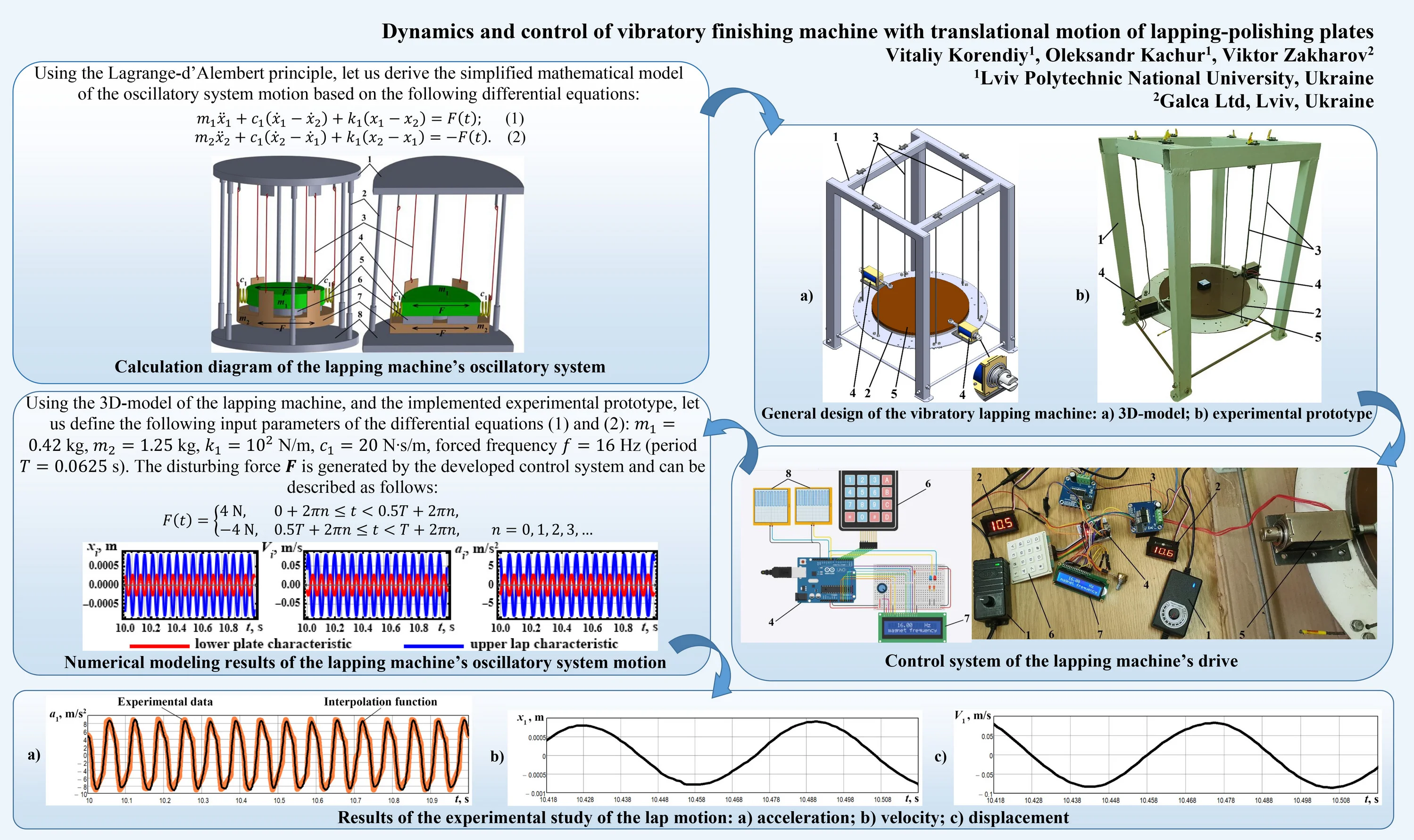
One of the main ideas of this paper consists in developing the double-mass vibratory machine for carrying out the single-sided lapping (polishing) of flat surfaces (see Fig. 1).
The machine’s body consists of the stationary frame assembled of the unmovable upper and lower plates (positions 1 and 8, respectively), and rigid vertical rods 2. The double-mass oscillatory system is suspended from the upper plate 1 by the flexible ropes (cables) 3. The upper lap 4 is connected with the lower plate 7 by a set of the coil springs 5. The parts 6 being treated are fixed on the lower plate 7. The horizontal periodic disturbing force is applied between the lap 4 and plate 7, and is directed along the springs’ longitudinal axes.
Using the Lagrange-d’Alembert principle, let us derive the simplified mathematical model of the oscillatory system motion based on the following differential equations:
where , denote the time functions of the upper lap and lower plate displacements; , are the masses of the lap and plate, respectively; is the stiffness coefficient of the coil springs; is the viscous friction coefficient taking into account the energy dissipation during the lap sliding over the parts being treated. This coefficient depends on numerous factors: lapping conditions, physical and mechanical properties of the lap’s and parts’ materials, specific features of the abrasive medium, etc., and can be determined experimentally. The characteristics of the periodic disturbing force depend on the drive and control type, and are considered below.
Fig. 1Calculation diagram of the lapping machine’s oscillatory system
2.2. Design diagram and experimental prototype of the vibratory lapping machine
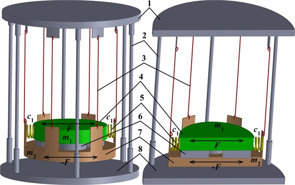
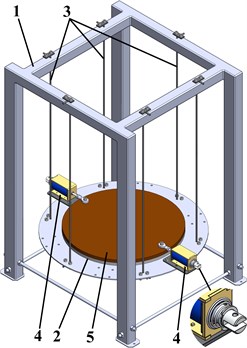
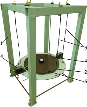
Based on the proposed design idea of the double-mass oscillatory system (Fig. 1), the corresponding 3D-model of the vibratory lapping machine has been developed in the SolidWorks software (see Fig. 2(a)). Its experimental prototype has been implemented at the Vibroengineering Laboratory of Lviv Polytechnic National University (see Fig. 2(b)). The machine’s frame 1 is welded using the square-shape tubes. The lower plate 2 is suspended from the flexible metal ropes (cables) 3 and is made of the mild (soft) AISI 1018 steel. Two driving electromagnets (push-pull-type linear solenoids ZUIDID KK-0520B) 4 are radially and oppositely fixed on the lower plate 2. The retractable rods (armatures) of the electromagnets 4 are spring-loaded and connected with the upper lap 5. The thin coat of the fine-grained abrasive medium Abro GP-201 is applied between the contacting surfaces of the lower plate 2 and the upper lap 5. The latter is made of the synthetic-resin bonded (SRB) paper laminate.
Fig. 2General design of the vibratory lapping machine: a) 3D-model; b) experimental prototype
a)
b)
3. Results and discussion
3.1. Developing the control system for the electromagnetic drive
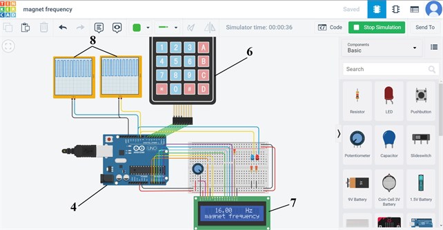
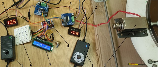
In order to provide the efficient near-resonance operation of the lapping machine’s oscillatory system, it is expedient to ensure the possibilities of changing the forced frequency and the maximal displacements of the electromagnets’ retractable rods. The corresponding control system has been developed using the Arduino software and hardware (Fig. 3). It provides the controllable forced frequency and supplying voltage of the electromagnets with the necessary phase (time) shifts. The phases of the electromagnets operation are opposite, and the corresponding control signals take the rectangular shape.
Fig. 3Control system of the lapping machine’s drive: 1) voltage regulator;2) voltage sensor; 3) driver; 4) Arduino controller; 5) electromagnet; 6) keyboard; 7) visual display; 8) oscilloscope
a)
b)
3.2. Numerical modeling of the lapping process
The mathematical modeling of the machine operation is carried out in the Mathematica software using the integrated Runge-Kutta methods. Using the 3D-model of the lapping machine, and the implemented experimental prototype, let us define the following input parameters of the differential Eq. (1) and (2): 0.42 kg, 1.25 kg, 102 N/m, 20 N∙s/m, forced frequency 16 Hz (period 0.0625 s). The disturbing force is generated by the developed control system and can be described as follows:
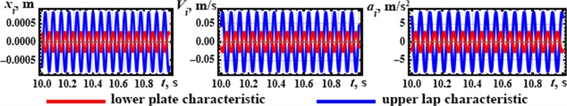
The results of numerical modeling are presented in the form of the graphical time dependencies of the upper lap and the lower plate displacements (), velocities (), and accelerations (). The maximal acceleration of the lap reaches 9 m/s2, whilst its maximal displacement (oscillation amplitude) is about 0.8 mm. Considering the lower plate, its maximal acceleration is about 3 m/s2, and the oscillation amplitude is equal to 0.27 mm. Based on the obtained results, it can be concluded that the oscillatory system’s relative motion parameters characterizing the lapping process reach the following maximal values: displacement – 1.1 mm; velocity – 0.12 m/s; acceleration – 12 m/s2.
Fig. 4Numerical modeling results of the lapping machine’s oscillatory system motion
4. Experimental investigations of the machine operation
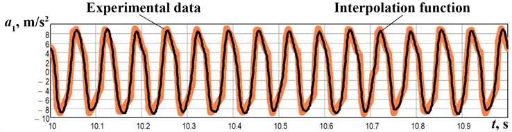
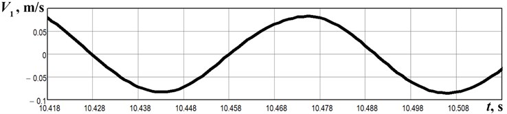
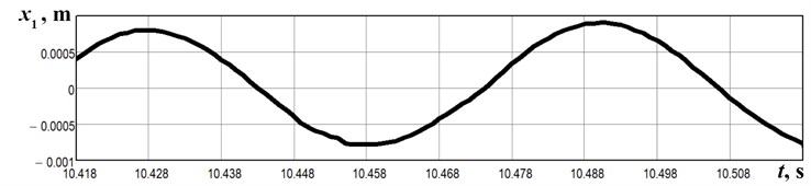
The experiments have been carried out at the forced frequency of 16 Hz. The absolute acceleration of the upper lap has been registered by the WitMotion BWT901CL accelerometer. The obtained experimental data (Fig. 5(a)) has been interpolated and numerically integrated using the built-in algorithms in the Mathematica software. The experimentally measured time dependencies of the lap velocity (Fig. 5(b)) and displacement (Fig. 5(c)) satisfactorily agree with the results of numerical modeling presented above (see Fig. 4).
Fig. 5Results of the experimental study of the lap motion: a) acceleration; b) velocity; c) displacement
a)
b)
c)
5. Conclusions
The present research is dedicated to the dynamics of the double-mass vibratory lapping (polishing) machine providing the single-sided treatment of the flat surfaces. The mathematical model of the machine’s double-mass vibratory system is developed using the Lagrange-d’Alembert principle. The simplified experimental prototype of the vibratory lapping machine with double-magnet excitation system is designed in the SolidWorks software and implemented in practice. The corresponding control system ensuring the efficient near-resonance operation is developed based on the Arduino software and hardware. The numerical modeling of the lapping process is carried out with the help of the Mathematica software. According to the theoretical and experimental results, the maximal acceleration of the lap reaches 9 m/s2, whilst its maximal displacement (oscillation amplitude) is about 0.8 mm. The proposed design ideas and obtained research results can be effectively used while designing the novel lapping and polishing equipment, and while implementing new techniques of finishing treatment.
References
-
A. Barylski and N. Piotrowski, “Optimization of kinematic parameters in single-sided lapping,” Mechanik, Vol. 90, No. 10, pp. 879–881, Oct. 2017, https://doi.org/10.17814/mechanik.2017.10.134
-
A. Barylski and N. Piotrowski, “Non-conventional approach in single-sided lapping process: kinematic analysis and parameters optimization,” The International Journal of Advanced Manufacturing Technology, Vol. 100, No. 1-4, pp. 589–598, Jan. 2019, https://doi.org/10.1007/s00170-018-2644-z
-
Y. Hashimoto, T. Sano, T. Furumoto, and A. Hosokawa, “Development an identification method of friction coefficient between wafer and carrier in double-sided lapping,” Precision Engineering, Vol. 56, pp. 364–369, Mar. 2019, https://doi.org/10.1016/j.precisioneng.2019.01.005
-
T. Deaconescu and A. Deaconescu, “Developing an analytical model and computing tool for optimizing lapping operations of flat objects made of alloyed steels,” Materials, Vol. 13, No. 6, p. 1343, Mar. 2020, https://doi.org/10.3390/ma13061343
-
Z. Chen, D. Wen, J. Lu, J. Yang, and H. Qi, “Surface quality improvement by using a novel driving system design in single-side planetary abrasive lapping,” Materials, Vol. 14, No. 7, p. 1691, Mar. 2021, https://doi.org/10.3390/ma14071691
-
R. Ji, L. Zhang, L. Zhang, Y. Li, S. Lu, and Y. Fu, “Processing method for metallic substrate using the liquid metal lapping-polishing plate,” Frontiers in Materials, Vol. 9, pp. 1–9, May 2022, https://doi.org/10.3389/fmats.2022.896346
-
W. Yao, J. Yuan, F. Zhou, Z. Chen, T. Zhao, and M. Zhong, “Trajectory analysis and experiments of both-sides cylindrical lapping in eccentric rotation,” The International Journal of Advanced Manufacturing Technology, Vol. 88, No. 9-12, pp. 2849–2859, Feb. 2017, https://doi.org/10.1007/s00170-016-8980-y
-
S. Park, D. Koh, J. Shim, J.-J. Kim, and S.-K. Lee, “Gantry type lapping manipulator toward unmanned lapping process for a large work surface,” International Journal of Precision Engineering and Manufacturing-Green Technology, Vol. 8, No. 6, pp. 1723–1737, Nov. 2021, https://doi.org/10.1007/s40684-020-00274-8
-
D. A. Davidson, “Vibratory finishing: Versatile, effective, and reliable,” Metal Finishing, Vol. 106, No. 5, pp. 30–34, May 2008, https://doi.org/10.1016/s0026-0576(08)80123-7
-
F. Hashimoto and S. P. Johnson, “Modeling of vibratory finishing machines,” CIRP Annals, Vol. 64, No. 1, pp. 345–348, 2015, https://doi.org/10.1016/j.cirp.2015.04.004
-
S. Wan, Y. C. Liu, and K. S. Woon, “A simple general process model for vibratory finishing,” The International Journal of Advanced Manufacturing Technology, Vol. 86, No. 9-12, pp. 2393–2400, Oct. 2016, https://doi.org/10.1007/s00170-016-8379-9
-
Y. B. Tian, Z. W. Zhong, and S. J. Tan, “Kinematic analysis and experimental investigation on vibratory finishing,” The International Journal of Advanced Manufacturing Technology, Vol. 86, No. 9-12, pp. 3113–3121, Oct. 2016, https://doi.org/10.1007/s00170-016-8378-x
-
V. Borovets, O. Lanets, V. Korendiy, and P. Dmyterko, “Volumetric vibration treatment of machine parts fixed in rotary devices,” in Lecture Notes in Mechanical Engineering, pp. 373–383, 2021, https://doi.org/10.1007/978-3-030-68014-5_37
-
V. Korendiy, V. Zakharov, V. Gurey, P. Dmyterko, I. Novitskyi, and O. Havrylchenko, “Modelling the operation of vibratory machine for single-sided lapping of flat surfaces,” Vibroengineering Procedia, Vol. 38, pp. 1–6, Jun. 2021, https://doi.org/10.21595/vp.2021.22001
-
V. Korendiy et al., “Kinematic and dynamic analysis of three-mass oscillatory system of vibro-impact plate compactor with crank excitation mechanism,” Vibroengineering Procedia, Vol. 40, pp. 14–19, Feb. 2022, https://doi.org/10.21595/vp.2022.22393
Cited by
About this article

