Abstract
The paper’s objective is to study the dynamic parameters and operating conditions of the vibratory conveyor, which is based on the double-mass oscillatory system and equipped with the pull-type (single-cycle) electromagnetic exciter. The scientific novelty consists in substantiating the conveying capacity of various standard sizes of bolts at different operating conditions defined by the input parameters, particularly supplied voltage. In order to describe the conveying tray vibrations, the simplified mathematical model of the conveyor’s double-mass oscillatory system is developed using the Euler-Lagrange equations and is numerically solved in the Mathematica software with the help of the Runge-Kutta methods. The experimental investigations are carried out at the Vibroengineering Laboratory of Lviv Polytechnic National University and are focused on testing the conveying speed of various bolts at different motion conditions: detachable (bouncing, hopping, jumping over the conveying surface) and non-detachable (sliding along the conveying surface). The obtained results show the basic kinematic parameters of the conveying tray motion at different voltages supplied to the actuating electromagnet and the dependencies of the conveying speeds of various bolts at different motion conditions mentioned above. The paper may be useful for designers and researchers while improving and implementing similar vibratory equipment in various industries.
Highlights
- The paper studies the dynamic parameters and operating conditions of the vibratory conveyor based on the double-mass oscillatory system and equipped with the pull-type electromagnetic exciter.
- The simplified mathematical model of the conveyor’s double-mass oscillatory system is developed. The numerical modeling results show the basic kinematic parameters of the conveying tray motion.
- The experiments are conducted at Vibroengineering Laboratory of Lviv Polytechnic National University and are focused on testing the conveying speed of various bolts at different motion conditions.
1. Introduction
Vibratory conveyors, screens, sieves and other technological equipment are widely used in various areas of human activity, particularly in the chemical, mining, pharmaceutical, instrument-making, machine-building, textile, and metallurgy industries etc. Numerous scientific papers are devoted to studying the dynamic behaviour and operational efficiency of vibratory conveyors. These machines are usually equipped with inertial exciters based on unbalanced rotors [1]-[5]. For example, the mathematical modelling and experimental studies of a vibratory conveyor developed for feeding bulky and loose products are carried out in [1]. The paper [2] is focused on investigating the possibilities of reducing the conveyor influence on the foundation it is mounted on. In [3], the authors conducted thorough research on the vibratory conveying of different wood pallets. The vibratory machine, equipped with the eccentric (unbalanced) exciter and designed for finishing treatment of parts, is considered in [4]. Another comprehensive study on the motion conditions of the single-mass vibratory conveyor is presented in [5].
Along with inertial drives (unbalanced rotors), crank-type mechanisms are also commonly used in vibratory equipment [6]-[11]. For example, the paper [6] considers an enhanced vibratory feeder characterized by linear oscillations of the working member and actuated by an asynchronous motor. In [7], there are studied the kinematics and dynamics of the shaking conveyor based on the closed mechanism with five movable links. A similar design of the screening conveyor with two working members (conveying tray and sieving screen) is considered in [8] from the viewpoint of its kinematics. The design optimization technique aimed at maximizing the conveying speed of the double-mass vibratory feeder with crank-type exciter is presented in [9]. The papers [10] and [11] are dedicated to investigating the kinematic and dynamic parameters of the novel crank-type excitation mechanism and studying its application in the three-mass vibratory system characterized by resonance operating conditions.
The problems of equipping vibratory conveyors with piezoelectric exciters ensuring the controllable actuating signals are thoroughly studied in [12] and [13]. An interesting and comprehensive research on the dynamics, control and operational peculiarities of an electromagnetically-driven resonant vibratory conveyer with rectilinear oscillations of the working member is published in [14]. The present paper is based on the previous investigations presented in [15] and [16] and focused on substantiating the inertial and stiffness parameters of the three-mass vibratory conveyors and other technological machines providing their efficient near-resonance operation. This research is aimed at studying the dynamic behaviour of the double-mass vibratory conveyor equipped with the pull-type electromagnetic exciter. The scientific novelty resides in determining the conveying speeds of various standard sizes of bolts under different operating conditions (accelerations and amplitudes of the conveying tray).
2. Research methodology
2.1. 3D-model of vibratory conveyor
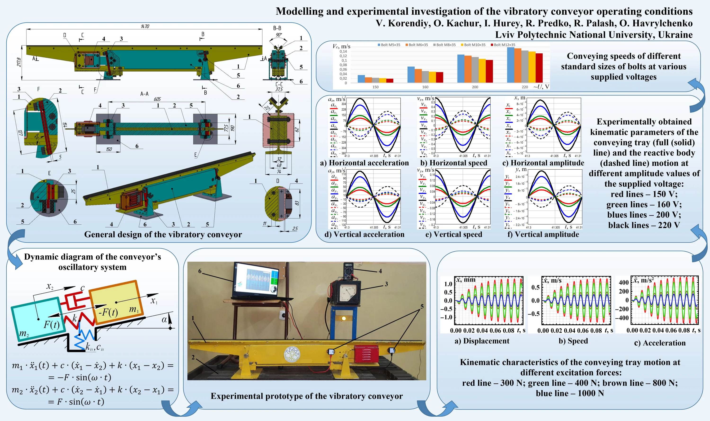
The conveyor (Fig. 1) is based on the double-mass oscillatory system characterized by the coincident mass centres of the working member 1 and the reactive body 2. This fact allows for eliminating the parasitic (angular) oscillations and providing a uniform conveying speed.
The main (central) member of the working body (conveying tray) 1 is made of the I-beam IPE160, in which the upper flange is cut off, the lower one is milled, and the additional design elements (holes, cuts, chamfers, etc.) are applied. On the lower flange, there are fixed supporting shoes to which the flat springs 3 are connected. At the rear end of the I-beam, the armature of the electromagnetic exciter 4 is installed. The conveying tray (equal angle) is welded to the upper end of the I-beam’s web. In the case of conveying the significantly larger parts, the additional strips (bars) can be attached to the angle. The reactive (non-conveying, disturbing) body 2 consists of two thick cheeks (plates), which are fixed to one another by a set of bolts freely passing through the corresponding holes drilled in the I-beam’s web. Four sets of flat springs 3 are connected to the bevelled end faces of the cheeks. In order to improve the springs fixation (restraint), additional metal sleeves (spacers) are installed between the springs at the corresponding fixation positions. At the rear end of the reactive body 2, the pull-type (single-cycle) electromagnet 4 with the frame-type coil is installed. The conveyor is mounted on the stationary base (foundation) 6 with the help of the arms (brackets) extending from the flat springs 3 and supported by the rubber vibration isolators 5. The positions of the arms correspond to the springs’ “zero-motion” points, which are almost unmovable due to the antiphase oscillations of the working member 1 and the reactive body 2. This allows for reducing the negative influence of the conveyor’s vibrations upon the stationary base (foundation) 6.
The vibratory conveyor is driven by the electromagnet 4 powered by a controllable voltage (within the range of 0…220 V) at the forced frequency of 100 Hz. The periodic electromagnetic pulling force acting between the armature (attached to the working member 1) and the core (fixed on the reactive body 2) excites the antiphase oscillations of the conveyor’s elements. Due to applying the inclined flat springs 3 connecting the vibrating bodies, the rectilinear oscillations of the working member (conveying tray) are generated at a specific angle to the horizon. This allows for conveying various piecewise products along the tray at different operating conditions (detachable (bouncing, hopping, jumping over the conveying surface) and non-detachable (sliding along the conveying surface)) depending on the kinematic characteristics (horizontal and vertical accelerations and speeds) of the tray.
Fig. 1General design of the vibratory conveyor
2.2. Dynamic diagram and mathematical model of the conveyor’s oscillatory system
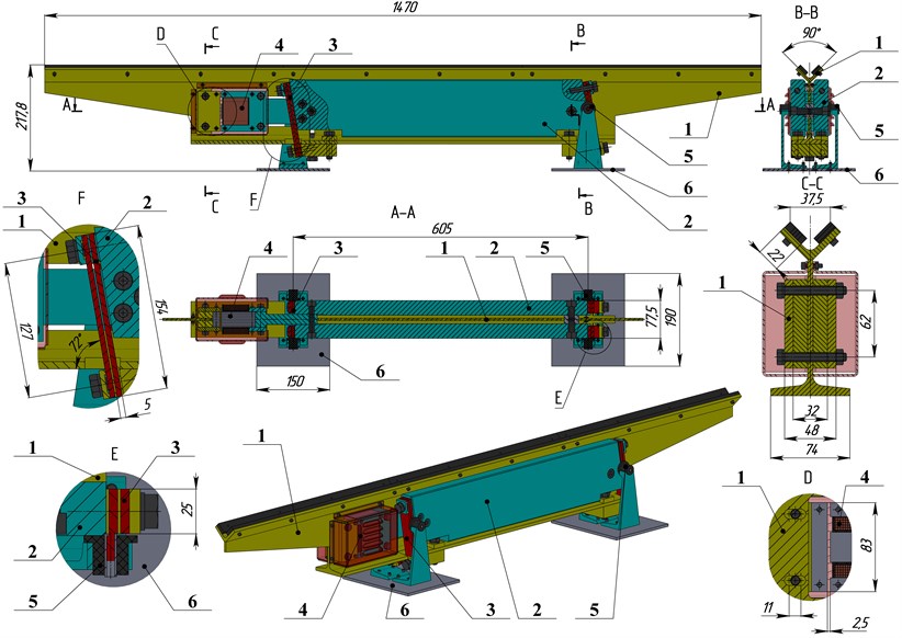
Based on the developed design of the vibratory conveyor presented above, let us construct the dynamic diagram of its oscillatory system (Fig. 2). The latter consists of two solid bodies (of masses and ) connected with one another by a spring of stiffness . The value of is calculated as to provide the conveyor operation under the efficient near-resonance conditions with the regulation coefficient (0.94…0.98). The vibrations are excited by the periodic force of the amplitude value at the forced frequency . The energy losses in the oscillatory system are described by the damping coefficient . Due to the specific design of the conveyor’s flat springs, the system vibrations are not transmitted to the base (foundation). That’s why the vibration isolators characterized by the stiffness () and damping () coefficients are not considered in the simplified mathematical model:
2.3. Experimental technique and equipment
The experimental prototype of the vibratory conveyor (Fig. 3) has been manufactured and tested at the Vibroengineering Laboratory of Lviv Polytechnic National University. The conveyor 1 is mounted on the horizontal base 2. The electromagnetic exciter is powered by the adjustable-ratio autotransformer (moving-coil voltage regulator) 3, whose voltage is additionally monitored by the voltmeter 4. The control system is connected to a single-phase power supply socket of alternating voltage (220 V). The accelerometers 5 (WitMotion BWT901CL sensors) are fixed on the working member (conveying tray) and the reactive (disturbing) body. The experimental data is sent to the laptop 6 and processed with the help of the WitMotion software.
Fig. 2Dynamic diagram of the conveyor’s oscillatory system
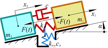
Fig. 3Experimental prototype of the vibratory conveyor
3. Results and discussion
3.1. Numerical modelling of the conveyor vibrations in the Mathematica software
Based on the 3D-design and experimental prototype of the vibratory conveyor, the following inertial parameters are obtained: 17.2 kg, 34.2 kg. The stiffness coefficient of the flat springs set (4.9·106 N/m) is calculated to provide the conveyor near-resonance operation at the forced frequency 100 Hz. The damping coefficient (600 N·s/m) is applied on the basis of previous authors’ investigations published in [15] and [16]. The amplitude values of the excitation force (300 N, 400 N, 800 N, 1 kN) have been experimentally measured in accordance with the voltages supplied to the electromagnetic exciter (150 V, 160 V, 200 V, 220 V). The results of numerical modelling carried out in the Mathematica software are presented in Fig. 4. The results show that the maximal displacement, speed, and acceleration of about 1.3 mm, 0.8 m/s, and 500 m/s2, respectively, are reached at the excitation force of the 1 kN magnitude.
Fig. 4Kinematic characteristics of the conveying tray motion at different excitation forces: red line – 300 N; green line – 400 N; brown line – 800 N; blue line – 1000 N
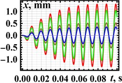
a) Displacement
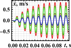
b) Speed
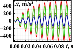
c) Acceleration
3.2. Results of experimental investigations
The experimental investigations have been conducted at different values of the supplied voltage (150 V, 160 V, 200 V, 220 V). The data obtained from the accelerometers has been processed in the WitMotion and MathCad software. The results of experiments are presented in Fig. 5 separately for horizontal and vertical directions of the conveying tray and reactive body motions. The maximal horizontal displacement, speed, and acceleration of the conveying tray (black solid lines in Fig. 5(a-c)) equal about 0.93 mm, 0.59 m/s, and 370 m/s2, respectively, and are reached at the supplied voltage of 220 V. The maximal values of the corresponding vertical kinematic parameters are about 0.3 mm, 0.19 m/s, and 120 m/s2, respectively (see Fig. 5(d-f)).
Fig. 5Experimentally obtained kinematic parameters of the conveying tray (full (solid) line) and the reactive body (dashed line) motion at different amplitude values of the supplied voltage: red lines – 150 V; green lines – 160 V; blues lines – 200 V; black lines – 220 V
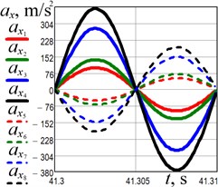
a) Horizontal acceleration
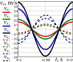
b) Horizontal speed
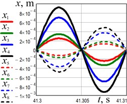
c) Horizontal displacement
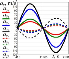
d) Vertical acceleration
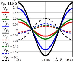
e) Vertical speed
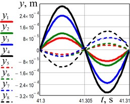
f) Vertical displacement
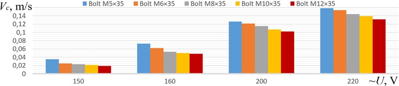
The last stage of experimental investigations is dedicated to studying the influence of the supplied voltage on the conveying speed of different standard sizes of bolts (ISO 4014): M5×35, M6×35, M8×35, M10×35, M12×35 (see Fig. 6). The largest conveying speed of about 0.16 m/s has been reached for the bolt M5×35 at the supplied voltage of 220 V. At the same excitation conditions, the largest bolt M12×35 moves at a speed of about 0.13 m/s.
Fig. 6Conveying speeds of different standard sizes of bolts at various supplied voltages
4. Conclusions
The dynamic behavior and operating conditions of the vibratory conveyor based on the double-mass oscillatory system and equipped with the pull-type electromagnetic exciter are studied. The mathematical model of the conveyor’s oscillatory system is derived and numerically solved. The experimental prototype of the conveyor is tested at different supplied voltages. The simulation and experimental results satisfactorily agree. The maximal horizontal and vertical displacement, speed, and acceleration of the conveying tray equal about 0.93 mm and 0.3 mm, 0.59 m/s and 0.19 m/s, 370 m/s2 and 120 m/s2, respectively, and are reached at the supplied voltage of 220 V. The experimental study on the conveying speed of different standard sizes of bolts showed that the largest speed of about 0.16 m/s is reached for the bolt M5×35 at the supplied voltage of 220 V. The obtained results may be useful for designers and researchers while improving and implementing similar vibratory equipment in various industries.
References
-
D. Gelnar, R. Prokeš, L. Jezerska, and J. Zegzulka, “Wood pellets transport with vibrating conveyor: experimental for DEM simulations analysis,” Scientific Reports, Vol. 11, No. 1, pp. 1–19, Dec. 2021, https://doi.org/10.1038/s41598-021-96111-2
-
Bednarski and J. Michalczyk, “Modelling of the working process of vibratory conveyors applied in the metallurgical industry,” Archives of Metallurgy and Materials, Vol. 62, No. 2, pp. 721–728, Jun. 2017, https://doi.org/10.1515/amm-2017-0109
-
P. Czubak and M. Gajowy, “Influence of selected physical parameters on vibroinsulation of base-exited vibratory conveyors,” Open Engineering, Vol. 12, No. 1, pp. 382–393, Jun. 2022, https://doi.org/10.1515/eng-2022-0033
-
V. Borovets, O. Lanets, V. Korendiy, and P. Dmyterko, “Volumetric vibration treatment of machine parts fixed in rotary devices,” in Lecture Notes in Mechanical Engineering, pp. 373–383, 2021, https://doi.org/10.1007/978-3-030-68014-5_37
-
M. Sturm, “Modification of the motion characteristics of a one-mass linear vibratory conveyor,” Vibroengineering Procedia, 2018, Vol. 19, pp. 17–21, Sep. 2018, https://doi.org/10.21595/vp.2018.20185
-
M. Buzzoni, M. Battarra, E. Mucchi, and G. Dalpiaz, “Motion analysis of a linear vibratory feeder: Dynamic modeling and experimental verification,” Mechanism and Machine Theory, Vol. 114, pp. 98–110, Aug. 2017, https://doi.org/10.1016/j.mechmachtheory.2017.04.006
-
Y. Yeleukulov et al., “Mechanical analysis of vibratory conveyor mechanism,” MATEC Web of Conferences, Vol. 226, p. 01019, 2018, https://doi.org/10.1051/matecconf/201822601019
-
V. Korendiy, O. Kachur, and P. Dmyterko, “Kinematic analysis of an oscillatory system of a shaking conveyor-separator,” in Lecture Notes in Mechanical Engineering, pp. 592–601, 2022, https://doi.org/10.1007/978-3-030-91327-4_57
-
Van Xo Nguyen and N. S. Golikov, “Analysis of material particle motion and optimizing parameters of vibration of two-mass GZS vibratory feeder,” Journal of Physics: Conference Series, Vol. 1015, No. 5, p. 052020, May 2018, https://doi.org/10.1088/1742-6596/1015/5/052020
-
V. Korendiy, O. Lanets, O. Kachur, P. Dmyterko, and R. Kachmar, “Determination of inertia-stiffness parameters and motion modelling of three-mass vibratory system with crank excitation mechanism,” Vibroengineering Procedia, Vol. 36, pp. 7–12, Mar. 2021, https://doi.org/10.21595/vp.2021.21924
-
O. Lanets, O. Kachur, V. Korendiy, and V. Lozynskyy, “Controllable crank mechanism for exciting oscillations of vibratory equipment,” in Lecture Notes in Mechanical Engineering, pp. 43–52, 2021, https://doi.org/10.1007/978-3-030-77823-1_5
-
C.-Y. Lee, T.-A. Teng, and C.-M. Hu, “A two-way linear piezoelectric vibratory conveyor actuated by a composite sinusoidal voltage input,” Journal of Vibroengineering, Vol. 23, No. 2, pp. 316–326, Mar. 2021, https://doi.org/10.21595/jve.2020.21703
-
B.-G. Kim, B.-H. Kang, S.-B. Choi, and G.-W. Kim, “Modeling and performance analysis of linear part feeder system actuated by piezoelectric transducers,” International Journal of Precision Engineering and Manufacturing, Vol. 23, No. 1, pp. 57–65, Jan. 2022, https://doi.org/10.1007/s12541-021-00608-9
-
V. Despotović, D. Urukalo, M. R. Lečić, and A. Ćosić, “Mathematical modeling of resonant linear vibratory conveyor with electromagnetic excitation: simulations and experimental results,” Applied Mathematical Modelling, Vol. 41, pp. 1–24, Jan. 2017, https://doi.org/10.1016/j.apm.2016.09.010
-
V. Korendiy, O. Kachur, Y. Novitskyi, V. Mazuryk, and V. Sereda, “Substantiation of parameters and modelling the operation of three-mass vibratory conveyer with directed oscillations of the working element,” Avtomatizacìâ virobničih procesìv u mašinobuduvannì ta priladobuduvannì, Vol. 53, pp. 84–100, 2019, https://doi.org/10.23939/istcipa2019.53.084
-
V. Gursky, V. Korendiy, I. Kuzio, and O. Kachur, “A new method of optimization synthesis of vibro-impact systems,” in Lecture Notes in Mechanical Engineering, pp. 91–100, 2022, https://doi.org/10.1007/978-3-031-06044-1_9
About this article

The authors have not disclosed any funding.
The datasets generated during and/or analyzed during the current study are available from the corresponding author on reasonable request.
The authors declare that they have no conflict of interest.
