Abstract
This paper presents mathematical modeling and analysis of shimmy oscillations for a light weight airplane single wheel nose landing gear. Shimmy is a self-excited oscillation which occurs usually on the nose wheel landing gear assembly during ground maneuvers which is governed by the dynamic characteristics of the landing gear and tires. Shimmy oscillation may lead to reduce the fatigue life of the landing gear and fuselage structure. So, the study of dynamic response and stability boundaries of landing gear plays crucial role while designing of airplanes. In earlier studies of vehicle shimmy only 3 degrees of freedom (DOF) considered such as torsional mode, lateral bending mode and tire lateral deformation. In this work along with above mentioned DOF, two more additional DOF introduced such as axial vibration of strut and tire in order to include the effect of vertical dynamics on shimmy model. Gyroscopic coupling effect also included in the model to study its influence on shimmy. Analysis carried out to determine critical velocity region for occurrence of shimmy and to investigate the effectiveness of ground unevenness on the landing gear system for two different runway conditions such as flat runway and random roughness runway. The results are more helpful to study significant interaction between the different parameters of landing gear and to represent stability boundaries.
1. Introduction
Lightweight airplanes are extensively used for surveillance, reconnaissance, defense and military. Development of airplanes integrating with a critical component like landing gear is a challenging task. Airplanes may be operated in both prepared and unprepared runways for takeoff, landing and ground maneuvers. So, efficient, good, robust and easy to maintain landing gear is required to ensure safety and comfort. A literature review is made on the previously published articles for wheel shimmy. In [1] the maximum total force with the random runway roughness of landing gears are obtained. Stability analysis of main landing gears are illustrated in [2]. In [3] stability of the system determined based on eigenvalues. Analysis of nonlinear differential equations using linearization techniques is presented in [4]. Linear and non-linear stability analysis of the nose landing gear model discussed in [5]. Percentages of the stable regions are computed by stability analysis conducted in different planes with different parameters given in [6]. Modeling of shimmy analysis is presented in [7]. Stability analysis for airplane with landing gear and shimmy damper illustrated in [8]. From the stability analysis limit of the shimmy amplitude and the magnitude of initial disturbance to initiate the self-excited oscillation are determined in [9].Various analytical and graphical methods to determine the stability margins for nonlinear systems are presented in [10].Vehicle shimmy with the effect of nonlinear tire forces, and the steering mechanism are investigated in [11] with the tire lateral forces are modeled by using cubic equation rather than popular magic formula. In [12] the potential effect of the two structural modifications to the parameters design ranges for the shimmy damper are investigated. Landing gear dynamics with torsional DOF and freeplay is investigated in [13]. Tire is modeled using the elastic string theory. Forces acting on the wheel are transmitted from the ground through the tire, and these forces also deflect the tire. In [14] active landing gears random vibration analysis are presented. Active landing gear responses are compared to the passive system. In [15] lateral response of the landing gear investigated with the effect of ground unevenness using mathematical model. Summary of the literature survey on solving landing gear vibration problems are presented in [16]. In this paper, mathematical model is developed to analyze the shimmy oscillation of nose wheel landing gear with consideration of total 5 DOF such as torsional angle , lateral bending angle , axial displacement of strut , axial displacement of tire and slip angle . Dynamics equations derived using second Lagrange equation. The stability boundaries of the model are determined based on the critical velocity regions for occurrence of shimmy. Dynamic responses of the model on two different runways in both stable and unstable regions of velocity are compared.
2. Dynamic model of nose landing gear
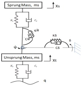
Simple trailing wheel system shown in Fig. 1 represents side view, top view, and front view along with direction of vertical load, forward velocity, torsion angle and lateral bending angle. Mathematical model of nose wheel landing gear shimmy due to axial, torsional and lateral vibration is shown in Fig. 2. The model of consists of wheel with tire of radius fitted with axle of the shock strut. The single point contact tire model is considered for analysis. The vertical load acts on landing gear comes from airframe and aircraft forward velocity is given as inputs to model. Dynamic model considers five DOF such as the shimmy angle of the nose wheel landing gear , lateral bending angle , the axial displacement of the tire , the axial displacement of the strut and slip angle of the leading contact point., , , , , represents the torsional, bending, vertical stiffness and damping coefficients for nose landing gear strut respectively. The damping and stiffness coefficient for tire are mentioned as and . and represents sprung mass corresponding to nose landing gear and unsprung mass of wheel assembly.
Fig. 1Simple trailing wheel system
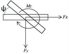
a) Top view
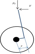
b) Side view
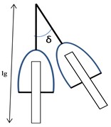
c) Front view
Fig. 2Mathematical model of landing gear with axial, torsional and lateral vibration
Based on Lagrange’s principle, equations of motion of damped multi degree-of-freedom system are written as shown in Eq. (1-9):
where is kinetic energy of the model, is potential energy of the model, is dissipative potential function of the model, is the generalized force to which each DOF of the system is subjected, and represents the generalized coordinate of the system, which is expressed as ]:
The differential equations of motion of the landing gear model is derived based on the second Lagrange equation:
where , - are coefficients for tire formula, and is the nominal load of the tire, then and , , and:
where , , and:
The relation governing stretched string tire model can be expressed as:
3. Numerical analysis
Based on the mathematical model the dynamic response obtained using MATLAB/Simulink. The developed Simulink model is shown in Fig. 3. Using solver ode 45 equations of motion are resolved. Analysis of nose wheel landing gear carried out by considering initial value of the torsion angle as 0.001 radians on two different runway conditions such as flat runway and random roughness runway. The random runway roughness can be modeled by PSD function. By measuring the surface profile PSD function can be determined, Quality of runway is graded based on roughness variance and roughness index in the domain of power spectral density as illustrated in [17]. By increasing the roughness variance the runway characteristics changes from very good to very poor. Runway grade considered in this work is very poor grade with roughness variance = 0.032 m; roughness inde 0.127 rad/m The parameters used for analysis are taken from [7] and the tire parameters are used from [9] which are listed in Table 1.
Fig. 3Simulink model for Nose wheel landing gear
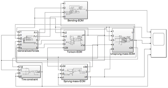
Table 1Landing gear and tire parameters
Parameter | Value | Unit |
Forward velocity, | 0-80 | m/s |
Vertical force, | 8000-12000 | N |
Sprung mass | 750 | Kg |
Unsprung mass | 38 | kg |
Caster length, | 0.1 | m |
Caster angle, | 0.08 | rad |
Distance from the wheel center to strut, | 0.068 | m |
Distance from the wheel center to the hinge center, / | 0.48 | m |
Strut torsional stiffness, | 100000 | Nm./rad |
Strut torsional damping, | 45 | Nm.s/rad |
Strut vertical stiffness, | 31600 | N/m |
Strut vertical damping, | 2300 | Ns/m |
Strut lateral bending stiffness, | 3240000 | Nm./r |
Strut lateral bending damping, | 1 | Nm.s/rad |
Strut moment of inertia about -axis, | 1 | kg.m2 |
Strut moment of inertia about -axis, | 1 | kg.m2 |
Strut moment of inertia about -axis, | 1 | kg.m2 |
Tire parameters | ||
Radius of nose wheel, | 0.36 | m |
Contact patch length, | 0.1 | m |
Relaxation length, | 0.3 | m |
Vertical stiffness of tyre | 260 | KN/m |
Vertical damping of tyre | 4.066 | KN.s/m |
Tire coefficient | –30.30 | KN/rad |
Tire coefficient | –7.96 | 1/rad |
Tire coefficient | 3250 | KN/rad^3 |
Nominal load of tire | 4700 | N |
4. Results and discussion
Parameters given in Table 1 are used for analysis of nose landing gear. The shimmy model solved in Matlab/Simulink. Dynamic-response to study the effect of runway roughness and its interaction with shimmy amplitude are presented. Fig. 4 shows that velocity range of shimmy will be enlarged when sprung mass increases for the system with sprung mass of 750 kg, it can be observed from figure 4a that the shimmy angle amplitude is 0.045 radian for flat runway whereas for random roughness runway shimmy angle amplitude is 0.15 radian. In both the runways velocity less than 54 km/h the system is stable and from 54 km/h to 152 km/h, the system is unstable, and system becomes stable above 152 km/h. It is found that the critical velocity of instability is from 54 km/h to 152 km/h for the case of NLG configuration of sprung mass 750 kg. Similarly for the system with sprung mass of 1000 kg, it can be observed from figure 4a that the shimmy angle amplitude is 0.18 radian for flat runway whereas for random roughness runway shimmy angle amplitude is 0.24 radian. In both the runways velocity less than 33 km/h the system is stable and from 33 km/h to 210 km/h, the system is unstable, and system becomes stable above 210 km/h. The critical velocity of instability is from 33 km/h to 210 km/h for the case of NLG configuration of sprung mass 1000 kg. These results show that the amplitude of shimmy angle increases dramatically for random roughness runway when compared to the flat runway even though critical velocity region have less effect on runway roughness.
Fig. 4Aircraft velocity vs shimmy angle for two different mass
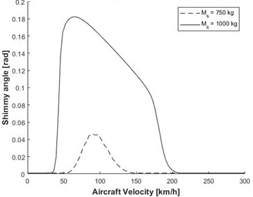
a) Flat runway
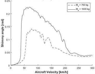
b) Random roughness runway
Fig. 5Time response for torsional angle ψ
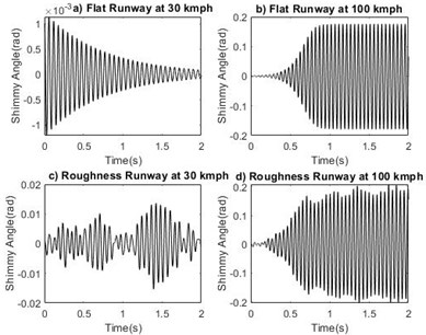
Fig. 6Phase portrait plot for torsional angle ψ
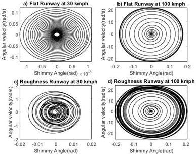
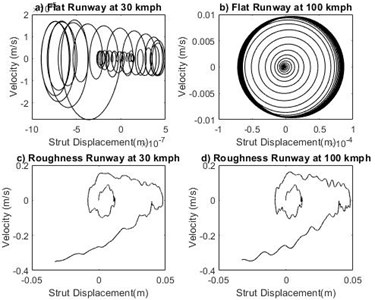
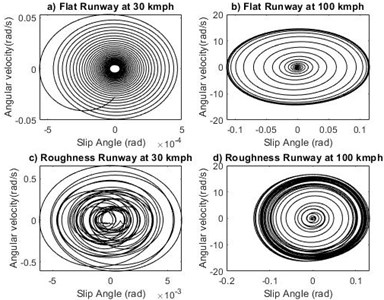
The study is made to compare the effect of two different runways at stable and unstable velocity regions. For system with sprung mass of 1000 kg, time response of shimmy angle on flat runway and random roughness runway at velocity 30 km/h and 100 km/h are shown in Fig. 5(a-d). From the Fig. 5 it is noted that in the critical velocity region time response diverges and the system exhibits unstable nature. Phase portrait plot of shimmy angle shown in Fig. 6(a-d). At the forward velocity of 30 km/h, the limit cycle is approached towards inside for both runways and at 100 km/h the limit cycle moves from inside to outwards on both runways. From the results shown in Figs. 7-14 it is observed that landing gear systems other shimmy influencing parameters such as lateral bending angle, tire displacement, strut displacement and slip angle makes nose landing gear system stable in the velocity lower than critical velocity region and the system becomes unstable upto higher critical velocity irrespective of the grade of runways.
Fig. 7Time response for bending angle δ
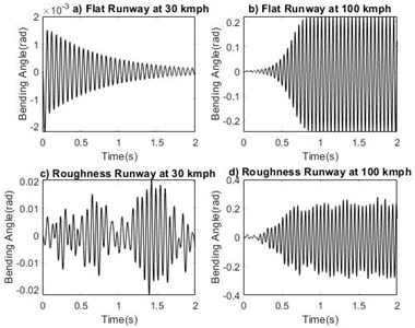
Fig. 8Phase portrait plot for bending angle δ
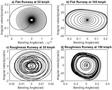
Fig. 9Time response for tire displacement xt
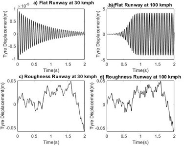
Fig. 10Phase portrait plot for tire displacement xt
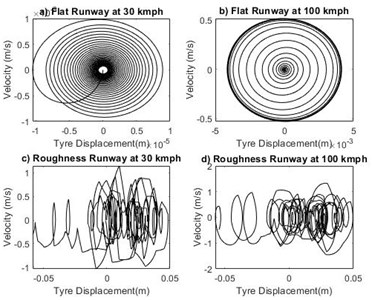
Fig. 11Time response for strut displacement, xs
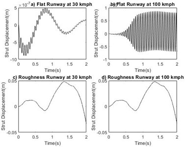
Fig. 12Phase portrait plot for strut displacement, xs
5. Conclusions
In this paper mathematical model of an aircraft nose landing gear developed with consideration of the vertical load acting on the wheel and the gyroscopic effects due to a rotation of wheel. Interaction of torsion, lateral, axial vibration of sprung mass, axial vibration of un sprung mass are investigated.
Fig. 13Time response for slip angle α
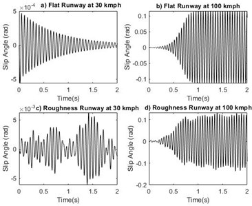
Fig. 14Phase portrait plot for slip angle α
The dynamic behaviour of shimmy model is studied for , , , , and are compared on two different runways in both stable and unstable regions of velocity. Based on the simulation results of mathematical model the following conclusions are made:
1. Critical velocity region for occurrence of shimmy enlarged when sprung mass , increases.
2. Amplitude of self-excited shimmy angle also increases by increasing sprung mass .
3. The amplitude of shimmy angle increases dramatically for random roughness runway when compared to the flat runway.
4. Dynamic responses decays when the velocity is in stable region and diverges when the velocity is in unstable region.
5. Phase portrait shows that the trajectory spiral up inwards for stable velocity regions and outward for unstable velocity regions.
6. Fatigue life of landing gear and fuselage structure may be improved if airplane is operated at velocity lower than critical velocity during ground roll.
7. Future work to study the influence of various landing gear parameters on shimmy vibration and to analyze stability nature.
References
-
S. Sivakumar, T. Selvakumaran, and B. Sanjay, “Investigation of random runway effect on landing of an aircraft with active landing gears using nonlinear mathematical model,” Journal of Vibroengineering, Vol. 23, No. 8, pp. 1785–1799, Dec. 2021, https://doi.org/10.21595/jve.2021.21915
-
Ijm Igo Besselink, “Shimmy of aircraft main landing gears,” Ph.D. Thesis, Technische Universiteit Delft, 2000.
-
C. Arreaza, K. Behdinan, and J. W. Zu, “Linear stability analysis and dynamic response of shimmy dampers for main landing gears,” Journal of Applied Mechanics, Vol. 83, No. 8, pp. 1–10, Aug. 2016, https://doi.org/10.1115/1.4033482
-
R. Morgan, “Linearization and stability analysis of nonlinear problems,” Rose-Hulman Undergraduate Mathematics Journal, Vol. 16, No. 2, pp. 67–91, 2015.
-
P. Thota, B. Krauskopf, and M. H. Lowenberg, “Shimmy in a nonlinear model of an aircraft nose landing gear with non-zero rake angle,” in 6th EUROMECH (European Mechanics Society) Nonlinear Dynamics Conference, 2008.
-
G. Somieski, “Shimmy analysis of a simple aircraft nose landing gear model using different mathematical methods,” Aerospace Science and Technology, Vol. 1, No. 8, pp. 545–555, Dec. 1997, https://doi.org/10.1016/s1270-9638(97)90003-1
-
H. Georgieva, “Modeling of shimmy oscillations in aircraft landing gear,” MATEC Web of Conferences, Vol. 133, p. 01007, 2017, https://doi.org/10.1051/matecconf/201713301007
-
N. K. Sura and S. Suryanarayan, “Lateral stability of aircraft nose-wheel landing gear with closed-loop shimmy damper,” Journal of Aircraft, Vol. 46, No. 2, pp. 505–509, Mar. 2009, https://doi.org/10.2514/1.37626
-
H. Wei, J.-W. Lu, S.-Y. Ye, and H.-Y. Lu, “Bifurcation analysis of vehicle shimmy system exposed to road roughness excitation,” Journal of Vibration and Control, Vol. 28, No. 9-10, pp. 1045–1056, May 2022, https://doi.org/10.1177/1077546320987791
-
G. Somieski, “An Eigenvalue method for calculation of stability and limit cycles in nonlinear systems,” Nonlinear Dynamics, Vol. 26, No. 1, pp. 3–22, 2001, https://doi.org/10.1023/a:1017384211491
-
L. Dai and Q. Han, “Stability and Hopf bifurcation of a nonlinear model for a four-wheel-steering vehicle system,” Communications in Nonlinear Science and Numerical Simulation, Vol. 9, No. 3, pp. 331–341, Jun. 2004, https://doi.org/10.1016/s1007-5704(02)00084-9
-
Yang Chen, “Time response simulation for nose landing gear shimmy damper design,” Thesis of Master of Applied Science, University of Toronto, 2018.
-
Freeplay, Elmas Atabay, and I. Ozkol, “On dynamics of a landing gear mechanism with torsional freeplay,” Global Journal of Researches in Engineering Aerospace Engineering, Vol. 12, No. 1, p. 16, 2012.
-
S. Sivakumar and A. P. Haran, “Aircraft random vibration analysis using active landing gears,” Journal of Low Frequency Noise, Vibration and Active Control, Vol. 34, No. 3, pp. 307–322, Jun. 2015, https://doi.org/10.1260/0263-0923.34.3.307
-
N. K. Sura and S. Suryanarayan, “Lateral response of nose-wheel landing gear system to ground-induced excitation,” Journal of Aircraft, Vol. 44, No. 6, pp. 1998–2005, Nov. 2007, https://doi.org/10.2514/1.28854
-
J. Pritchard, “Overview of landing gear dynamics,” Journal of Aircraft, Vol. 38, No. 1, pp. 130–137, Jan. 2001, https://doi.org/10.2514/2.2744
-
F. Tyan, Yu Hong, Shun-Hsu Tu, and W. Jeng, “Generation of random road profiles,” Journal of Advanced Engineering, Vol. 4, No. 2, pp. 151–156, 2009.
Cited by
About this article

The authors have not disclosed any funding.
The datasets generated during and/or analyzed during the current study are available from the corresponding author on reasonable request.
The authors declare that they have no conflict of interest.
