Abstract
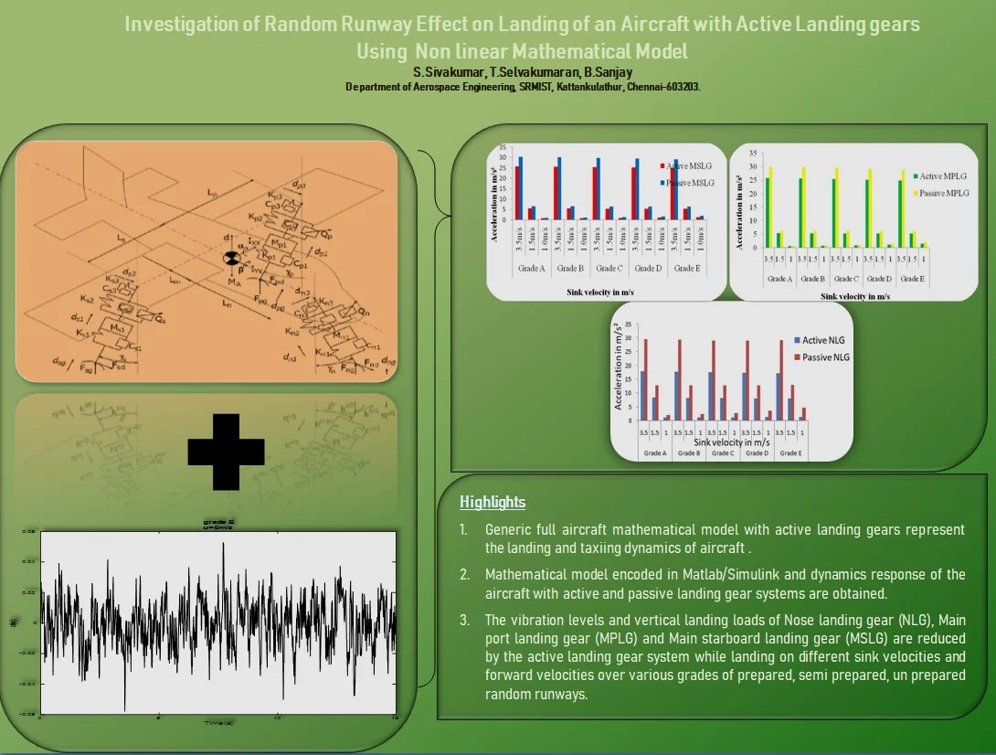
Random runway roughness effect on the dynamic response of an aircraft with landing gears has been investigated using nine degree of freedom nonlinear mathematical model. The developed mathematical model incorporates nonlinear characteristics of air spring stiffness, landing gear damping, tire stiffness and damping of the oleo pneumatic main landing gears and nose gear. Equation of motion for aircraft and each landing gear have been written considering heave, pitch, roll of aircraft and three vertical motions of landing gears respectively for landing response analysis. The equations for longitudinal motion of each landing gear are also written from the mathematical model will be helpful for longitudinal dynamics. The aircraft touchdown and roll on with variable decent velocities on Grade E random runway represented by nonstationary random process. The excitation of different grades of random runway can be considered as stationary random process when the aircraft landing at constant sink velocity. This work mainly focused on finding the dynamic responses of the aircraft such as heave, pitch, roll acceleration, vertical forces and all the three landing gears vertical vibration levels while landing on random runways. The active landing gear system performance is compared with passive landing gear system by numerical simulation in MATLAB/SIMULINK. The investigation using nonlinear model predicted that the effect of active control landing gear provides significant reduction in vibration levels and vertical reactions during landing at various vertical velocities on random runways. To validate the above mathematical model a multi-body dynamics (MBD) model has been simulated in ABAQUS/CAE and the dynamic responses of landing gear forces are compared with those obtained from the nonlinear mathematical model. The nonlinear model responses are also compared with the results of other authors. This study is more useful to adopt active control landing gear in the aircraft to reduce the landing loads transmit on aircraft structure and landing gears due to landing impact. The reduction of vibration levels and vertical forces by the active system increase the fatigue life of landing gears and structural life of airframe.
Highlights
- Generic non linear mathematical model of aircraft
- Landing dynamics for finding vertical vibrations and landing loads
- Stationary and non stationary random responses
1. Introduction
An Aircraft landing impact and excitations due to uneven runway surfaces are absorbed by the landing gear system. The successfully designed landing gear system dissipates kinetic energy generated during touchdown impact at higher sink rate and provide comfortable ride to passengers at a lower taxiing speed. The common landing gear fitted in all the aircrafts is an oleo pneumatic type behaves strongly nonlinear manner which influences the effectiveness of the landing system. Previous analytical and experimental studies [1]-[3] indicated that the potential benefits and feasibility of active control to landing gear to limit ground loads transmitted to airframe. The books of Currey, Roskam and Lomax are given the details of design principles, operation, layout and requirements of the landing gear [4]-[6]. Wang. et. al modeled a two degree of system model of active landing gear using PID controller to reduce the aircraft vibrations excited by runway undulations has been studied [7]. [8] suggested a hardware feasibility for active landing system. The ride comfort while taxiing on smooth runway with obstacles was investigated using linear model as in [9]. FAR/JAR 25. 479, 25. 491 guidelines has been used for calculation of ground loads during landing conditions for analysis. The linear and nonlinear dynamic response of high performance aircraft includes various descent cases has been studied [10]. The measurement of car vibration in three orthogonal axes transferred from road roughness was studied in [11]. The excessive vibrations due to runway roughness increase stress on landing gear components an aircraft structure which may lead to premature withdrawal or failure. It is very difficult for the pilot to focus on flight instrumentation and also controlling the control columns during landing, take off or taxiing. The dynamic response of the aircraft to runway surface irregularities increases vertical accelerations can also reduce the braking capacity. The damping capacity of conventional or passive landing gear cannot be adjustable when it encounters runway irregularities. The development of active landing gear is focused on this research work to overcome the difficulties of passive landing gear. The touchdown impact of nonlinear analysis of single landing gear was investigated by the author in [12]. In this study, the transverse drag forces at the axle are balanced by the engine thrust during three-point landing and the relationship of the drag load at the time of maximum vertical load is 0.25 and occurs at the time of maximum vertical load on the gears. These assumptions are taken for calculating ground reaction loads on the axle of the landing gears. The horizontal drag forces at the axle are producing moments during aircraft pitching motion, which are included in the equation for analysis. In this work, to predict the dynamic response on touchdown and roll out exactly, full aircraft nonlinear dynamic mathematical model has been developed considering the nonlinearities of air spring force, tire spring force and damping force of landing gears. Tire damping force is considered linear one. This investigation helps to determine the vibration levels, vertical reactions of aircraft and landing gears with active control system while landing on damaged runways. The developed nonlinear dynamic model is exactly helps to investigate the dynamic response of the active landing gear during touchdown impact by stationary and non stationary random analysis. In this work, the dynamic response of landing gear is validated with the ABAQUS/CAE multi body dynamics model. The aerodynamic drag forces and vertical drag forces at the axle are considered for deriving longitudinal equation of motions. Longitudinal dynamics and shimmy vibration analysis would be separately done in the future study.
2. Nonlinear mathematical model of Aircraft with active landing gears
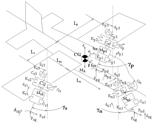
The mathematical model comprises of nine DOF, with three DOF (Heave , pitch , roll for the aircraft fuselage mass and three DOFs, , , for the vertical displacement of nose landing gear tire mass and rear main starboard, port landing gear tire masses , as shown in Fig. 1. , and represent the vertical motions due to ground unevenness applied as input , , , , , represent the nonlinear stiffness (spring force is a function of relative displacement (stroke)) and non linear damping (damping force is a function of relative displacement and relative velocity) parameters of Nose Landing Gear (NLG), Main Starboard side Landing Gear(MSLG) and Main Portside Landing Gear(MPLG) shock struts respectively. The nonlinear tire stiffness (tire spring force is a function of tire displacement) and damping parameters of tire denoted as , , , , , respectively. The longitudinal DOF , , is positive along the global x axis to represent the effect of spin up and spring back loads. , , , , , represents the bending stiffness and structural damping of nose, port and starboard landing gear respectively. , , , , , denotes the ground and drag force along vertical and longitudinal directions at the axle of NLG, MSLG and MPLG. The main landing gears fitted near to C.G of aircraft with negative rake angle , for good brake efficiency and the nose landing gear is installed with positive rake angle to steer the aircraft. Based on the reference work, rake angle ranges between 0 to 10 degrees. Whereas in this study, the rake angle considered is zero. The tricycle arrangement of oleo pneumatic landing gears considered with rigid airframe mass inertia and in the dynamic model. The lower and upper cylinder of the LG shock strut contains hydraulic oil and high pressure air/nitrogen respectively. The lateral motion of the landing gear and yaw motion of aircraft body would be considered for shimmy vibration study in future work.
Fig. 1Nonlinear mathematical model of aircraft with active landing gears
3. System dynamics
Considering assumptions such as small motions in linkages, maintaining of ground contact, ignoring gravity and measurement from equilibrium position, rigid aircraft body and linkages, no friction in the sliding members of landing gear, vertical motion alone for landing analysis, runway roughness depends on power spectral density, and operating speed, the governing equation of motion is written from the non linear mathematical model.
For Aircraft heave motion:
where, is lift of the aircraft. The lift is equal to weight of the aircraft is taken as per FAR 25.473 and , , are the active control force of NLG, MPLG, MSLG.
For Aircraft pitch motion:
where , , are radius of the tires in static loaded condition and , , are the vertical distance between the C.G of the aircraft and the LG axle respectively.
For Aircraft roll motion:
For NLG tire mass vertical motion:
For MSLG tire mass vertical motion:
For MPLG tire mass vertical motion:
The displacement and velocity functions of the attachment points of NLG, MSLG and MPLG are written as:
where and denote the distance from C.G to port and starboard side of MLG fitment, represents the longitudinal distance from the nose LG to C.G of aircraft, is longitudinal distance from C.G of aircraft to main LG fitment, is the eccentric lateral distance of NLG to C.G of aircraft.
In this work, non linear stiffness, damping characteristic is exactly considered for the vertical motion of the landing gear and tire assembly. When the tire touches the runway, spin up and spring back forces are developed and acting at the attachment of LG with the aircraft structure in the longitudinal direction.
For longitudinal motion, when the aircraft touches down, the aerodynamic drag is considered to be equally shared by NLG and MLGs. The longitudinal dynamics equations are written as in Eqs. (14-16).
For NLG tire mass longitudinal motion:
For MSLG tire mass longitudinal motion:
For MPLG tire mass longitudinal motion:
4. Active control sub system
In all the aircrafts, the centralized hydraulic system is utilized for operating the landing gear system components. The active control hydraulic circuit consists of sensors which are located in the LGs to measure the force, acceleration, velocity and displacement generated on touchdown can be supplied as input to the PID controllers of respective landing gears.
The controllers obtain the error function from the LG as the difference between reference signal and displacement, velocity and acceleration signal. The controller design is given by Eq. (17-20):
PID controllers for NLG, MSLG and MPLG are fitted individually for controlling servo actuators. The servo valve movement in the servo actuator of NLG is written as:
Similarly the movement of servo valve of MSLG and MPLG from the corresponding PID controllers as:
where the proportional gain, an integral gain, a differential gain are tuned by Ziegler-Nicholas tuning method initially and fine tuned manually to optimize the suitable control gains. The MSLG and MPLG tuned first with the gain values and NLG gain values are given in the Table 1.
Table 1Ziegler-Nichols tuning gain values of controller
Type of controller | Landing gear | |||
PID | MSLG &MPLG | 0. 724 | 0. 001 | 0. 0001 |
PID | NLG | 2. 124 | 0. 01 | 0. 0001 |
The controller sends the signals to operate the servo valve in the servo actuator. The active hydraulic circuit also accommodates reservoir, accumulator, electrically driven hydraulic gear pump, manifold, pressure relief valves, solenoid valves, fluid pipes and fittings.
The hydraulic flow through the servo actuator is determined by the Eq. (21):
The active control force is developed by the servo actuator depends on the signal from the PID controllers. The active control force is calculated by the Eq. (22) as in [13]:
When , there is a positive control force and negative control force in case of . The flow out or into the respective landing gears controlled by signal from the PID controllers. In case of failure of active control system, the passive landing gear can meet all the uncertainties during landing impact and taxiing. The safety and reliability of landing gear system is ensured by safety switch, ground locks, landing gear position indicators, and nose wheel centering and other devices fitted in the aircraft.
5. Generation of random road profiles
Power spectral density is used to specify the stationary runway roughness when airplane moves at a constant velocity v, the runway roughness can be represented as a stationary process in space domain and is the runway PSD, is the spatial angular frequency in rad/m and roughness co-efficient at the reference angular spatial frequency :
Runway waviness is considered for a range of from short to long wave length. Generally, is taken as 2. Inversion of wave length is noted as waviness. When introduce the spatial angular frequency () where is the spatial frequency .
The relationship between the angular velocity (rad/s) and the spatial angular frequency (rad/m) is described as :
where is the lowest cut off angular frequency. The equation can be considered as a response of a first order linear system to white noise excitation. From the theory of random vibration, the road roughness in frequency domain as shown:
where is the transfer function and is the PSD of white noise. According to Laplace transformation, the above equation can be written as:
It can be viewed as transfer function from white noise signal to runway roughness:
The above Eq. (27) represents transfer function from white noise signal to road roughness. The equation can be written as:
where is the road roughness, is a power spectral density is 1. The value of , the equation can be written as:
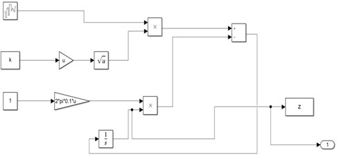
From the Eq. (29), the road roughness can be obtained. The road generator is constructed in Matlab/Simulink environment as given in Fig. 2.
Fig. 2Random road generator
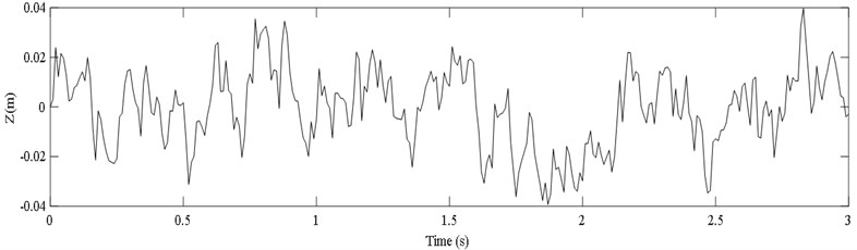
The roughness variances for various types of road surfaces are as given in [14]. The prescribed random road longitudinal profiles classification based on the International organization for standardization (ISO 8606). The ISO has proposed road roughness classification using power spectral density values. The following guidelines are taken from the ISO 8608 such as new roadway layers like asphalt or concrete layers can be assumed to have a good or even a very good roughness quality. Old roadway layers which are not maintained may be classified as having a medium roughness. Roadway layers consisting of cobble stones or similar material may be classified as medium (average) or bad (poor, very poor). Using the random road generator, the grade E random profile is generated as shown in Fig. 3.
Fig. 3Random road Grade E
6. Numerical solutions
Simulink model has been developed from the dynamic Eqs. (1-3) for aircraft heave, pitch and roll motion as sub systems. From the dynamic Eqs. (4-6), the subsystem of NLG, MPLG and MSLG are modeled. To cater the non linear stiffness and nonlinear damping characteristics of landing gear and tire, the lookup table tools are used in Simulink. The values from the non linear curves are entered in the one dimensional look up table which will retrieve input data for simulations. The displacement and velocity functions (7-13) are modeled as sub systems. The active control sub system is modeled for NLG, MPLG and MSLG as subsystems from the Eqs. (18-22). These sub systems are linked together to build full aircraft model. Matlab codes are written to define the input parameters of aircraft and landing gears for numerical simulations. A typical transport aircraft fuselage mass 22000 kg, The landing gear mass of nose = 130 kg, mass of port side main gear 260 kg, mass of starboard side 260 kg, distance from the aircraft C.G to main gears = 1.94 m, distance from C.G to nose gear = 7.76 m, distance from C.G to port side gear = 3.8425 m, distance from C.G to starboard gear = 3.8425 m, Aircraft pitch moment of inertia 100000 kgm2, Aircraft roll moment of inertia = 65000 kgm2. Non linearity of landing gear’s air spring stiffness, tire stiffness, and damping coefficient are taken from reference [9]. Tire damping of both gears considered linear as 4066 Ns/m. Horizontal drag force on the nose gear = 29026 N, horizontal drag force on the main landing gears and 41092 N, Static loaded radius of the nose gear = 0.29 m, main gears and = 0.48 m; Distance from the C.G to nose gear axle = 2.27 m, distance from the C.G to main gear axle and = 2.08 m, Aerodynamic lift of the aircraft 220000 N, The active control consists of accumulator charged with the pressure of = 2×10⁶ Pa, pressure of reservoir = 0.1×10⁶ Pa, density of hydraulic fluid = 912 kg/m3, discharge co efficient of = 0.1×10⁻⁵, area of the servo valve orifice = 0.002 m2 and is the displacement of the servo valve.
The landing response is investigated for design landing, take off condition and high rate condition as 1.5 m/s, 2 m/s, 2.5 m/s respectively in FAR 25. 723, 25. 725 and 25. 727. By using the nonlinear dynamic model, several numerical simulations have been done for aircraft and landing gears dynamic response behavior.
7. Non stationary random response on Grade E profile
Grade E profile is a very poor roughness road with a roughness co-variance of 0. 032 and road surface co-efficient 0. 127. The grade E road profile was generated by considering the aircraft forward velocity of 30 m/s as shown in Fig. 3. A number of simulations have been done in Simulink environment with sink velocities 1.5 m/s, 2 m/s, 2.5 m/s.
Figs. 4-7, shows that the acceleration and force response of the aircraft and landing gears touchdown at high sink velocity of 2.5 m/s and the nose gear land at 0.8 m/s. The forward speed of the aircraft is considered as 30 m/s. In the landing phase, first MSLG and MPLG touchdown on the runway then the NLG contacts due to pitch plane inertia after the aircraft de rotation. It is observed that responses exhibit transient oscillatory motion and subsequent damping occurs to settle at stable equilibrium position. The simulations results are tabulated in Table 2-3.
From the results indicated that aircraft heave acceleration reduced 18 % by the active system. The pitch and roll acceleration of both passive and active are almost similar below sink velocity of 2 m/s. The pitching and rolling acceleration slightly increasing at higher sink velocity by engaging the active control mode. The maximum force on the fuselage body due to heave, pitch and roll response decreased 18 % for all sink rates. The pitch and roll force reduced 24 % and 60 % respectively for lower velocities and slightly increased in case of higher velocity. From the Fig. 8, it is observed that the heave, pitch and roll displacement reduced by the active landing gear system at various landing velocities on smooth runway.
It is not able to compare exactly the results due to lack of same type of research paper. However, the current work of landing analysis compared with the results of taxiing analysis of same aircraft on random runways by the other authors. Hakan Yazici and Mert Sever [15] has obtained RMS values of a typical aircraft taxiing at a speed of 120 km/hr and 240 km/hr. The fuselage acceleration while taxiing on grade C, D, E random runway irregularities in the range of 0.112, 0.159 and 0.226 m/s² and for active landing gear using robust LQR controller is 0.038, 0.051 and 0.068 m/s² respectively. In this research work, the aircraft is landing at a descend velocity of 2.5 m/s and forward velocity 30 m/s. The fuselage heave acceleration while landing on grade C, D, E random type runway irregularities in the range of 0.659, 0.771 and 1.572 m/s² and for active landing gear using PID controller is 0.317, 0.467 and 1.246 m/s² respectively. It has been observed that there are higher acceleration levels during landing and considerable reduction of acceleration by the active system than passive one.
Fig. 4Aircraft rigid body acceleration response at sink velocity 2.5 m/s
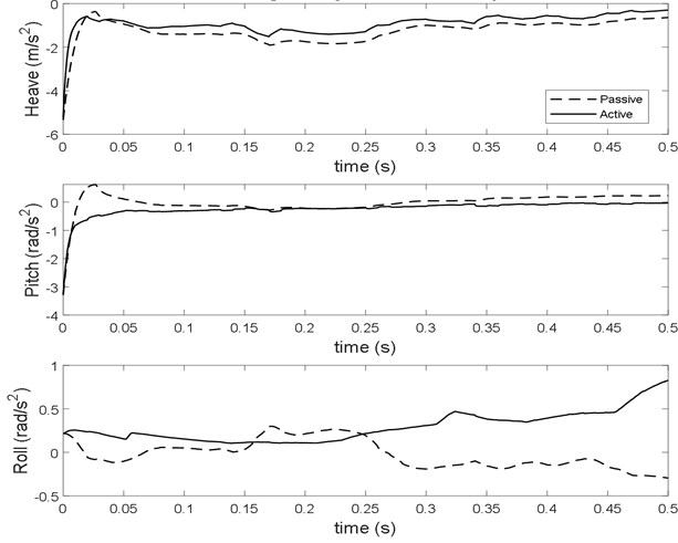
Fig. 5Aircraft rigid body force response at sink velocity 2.5 m/s
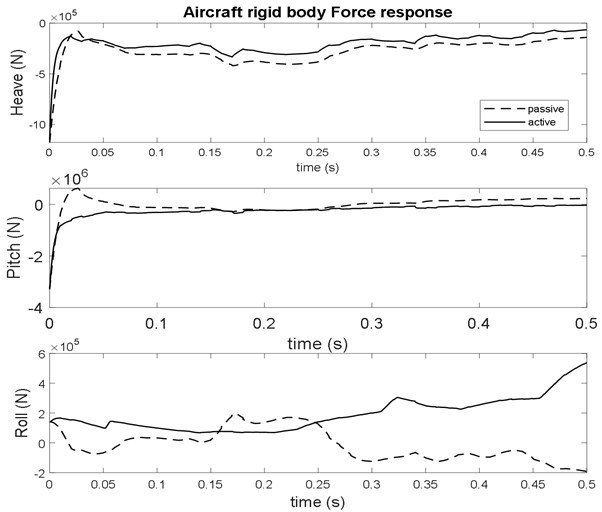
Fig. 6Landing gear vertical acceleration response at sink velocity 2.5 m/s
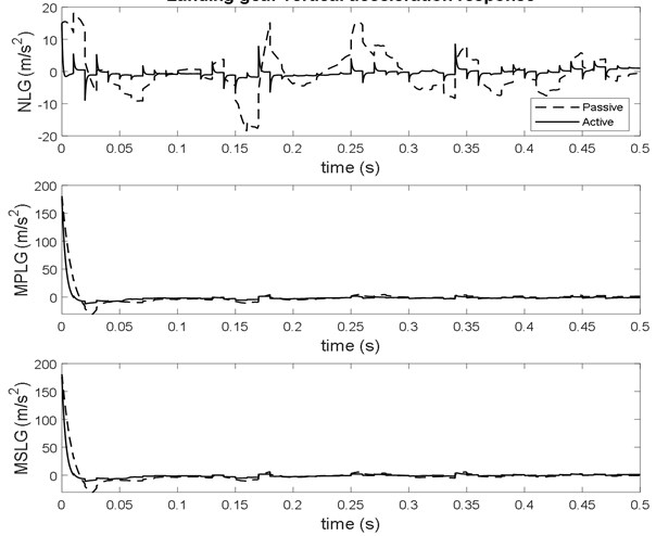
Fig. 7Landing gear vertical force response at sink velocity 2.5 m/s
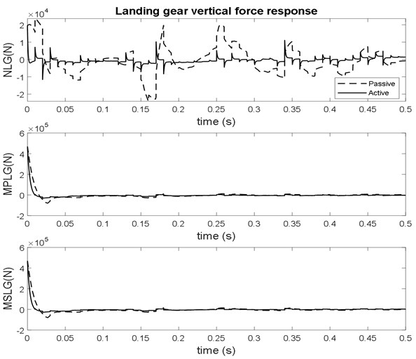
In the research work [16], the passive landing gear acceleration values for nose, right, left are 0.427, 1.529, and 2.580 m/s² and the active landing gear using LQR controller are 0.173, 0.751, and 1.423, and of same aircraft parameters while taxing meeting with bump input. During taxiing phase, the acceleration and force reduction for nose, right, left are 22.9 %, 53.33 % and 28.1 % respectively. The reduction of settling time is 25 % with the active system. In this work, From the Figs. 6-7 and Table 3, it is observed that the acceleration and force reduction of NLG, MSLG and MPLG is 56 %, 20 % and 20 % respectively obtained with the active controlled gears during touchdown on the runway. The settling time of vibration levels are also considerably reduced by the active landing gear system.
Fig. 8Variations of maximum heave, pitch, roll displacement of aircraft with sink velocity
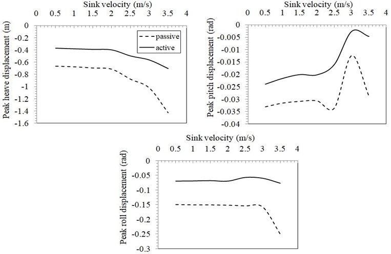
Table 2Dynamic response of aircraft to Grade E runway on landing
Acceleration | Force | |||||||||||
Heave (m/s²) (rms) | Pitch(rad/s²) (rms) | Roll(rad/s²) (rms) | Heave (N) (rms) | Pitch(N) (rms) | Roll(N) (rms) | |||||||
Sink rate | Passive | Active | Passive | Active | Passive | Active | Passive | Active | Passive | Active | Passive | Active |
1.5 m/s | 0.9695 | 0.8243 | 0.1029 | 0.6527 | 0.1860 | 0.0718 | 213290 | 181367 | 102969 | 65266 | 120962 | 46718 |
2.0 m/s | 0.9963 | 0.8259 | 0.0969 | 0.0858 | 0.1845 | 0.0742 | 219203 | 181707 | 96904 | 85834 | 119981 | 48275 |
2.5 m/s | 1.572 | 1.246 | 0.6400 | 0.6503 | 0.1609 | 0.3463 | 345842 | 225134 | 640034 | 650318 | 104625 | 225134 |
Table 3Dynamic response of landing gears to Grade E runway on landing
Acceleration | Force | |||||||||||
NLG (m/s²) (rms) | MPLG(m/s²) (rms) | MSLG(m/s²) (rms) | NLG (N) (rms) | MPLG(N) (rms) | MSLG(N) (rms) | |||||||
Sink rate | Passive | Active | Passive | Active | Passive | Active | Passive | Active | Passive | Active | Passive | Active |
1.5 m/s | 6.0853 | 2.7975 | 4. 2351 | 3. 2896 | 4. 3881 | 3. 3010 | 7910 | 3636 | 11011 | 8553 | 11409 | 8582 |
2.0 m/s | 5.8599 | 2.7203 | 5. 2792 | 4. 1903 | 5. 4146 | 4. 1997 | 7617 | 3536 | 13726 | 10894 | 14078 | 10919 |
2.5 m/s | 7.1447 | 2.7517 | 34.6702 | 28.9120 | 34.7600 | 28.8818 | 9288 | 3577 | 90142 | 75171 | 90376 | 75092 |
8. Stationary random response on different grades of runway
Different grades of random runway profiles are generated using the values given in the [14]. Considering the constant forward velocity of 30 m/s and with constant 2.5 m/s sink velocity of the aircraft, a series of landing simulations were carried out on grade C, D, E in the Matlab/Simulink Environment. The obtained values are tabulated in the Table 4. From the Table 4, it can be noted that there is a increase in vertical accelerations of aircraft and landing gear increases as the runway roughness increases. There is a considerable reduction of heave acceleration of aircraft and landing gears acceleration by the active mode control. The roll acceleration slightly increases when engaging the active system. The comparison also shows that the effectiveness of the active landing gear system for different grades of runways.
Table 4Dynamic response of aircraft and landing gears to Grade C, D and E runway
Acceleration | ||||||||||||
Heave (m/s²) (rms) | Pitch(rad/s²) (rms) | Roll(rad/s²) (rms) | NLG (m/s²) (rms) | MPLG(m/s²) (rms) | MSLG(m/s²) (rms) | |||||||
Grade | Passive | Active | Passive | Active | Passive | Active | Passive | Active | Passive | Active | Passive | Active |
C | 0.659 | 0.317 | 0.221 | 0.039 | 0.279 | 0.790 | 0.7558 | 1.023 | 1.447 | 1.423 | 1.238 | 1.215 |
D | 0.771 | 0.467 | 0.284 | 0.191 | 0.279 | 0.783 | 1.838 | 1.190 | 10.146 | 8.420 | 10.129 | 8.404 |
E | 1.572 | 1.246 | 0.640 | 0.645 | 0.160 | 0.346 | 7.144 | 2.751 | 34.670 | 28.912 | 34.760 | 28.881 |
9. Validation by aircraft landing dynamics simulation in ABAQUS/CAE
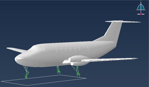
Multi-body dynamics (MBD) equivalent of the above nonlinear mathematical vibration model as shown in Fig. 9 has been simulated in ABAQUS/CAE. Similar system description holds good for the MBD model as that of the mathematical model parameters, described in Section 6. The approach in ABAQUS/CAE is a parameterized modeling of the aircraft with two main landing gears and a single nose landing gear. The multi body model is made of combined rigid and flexible parts in the same model. The nonlinear stiffness and damping characteristics of nose landing gear, main landing gears assigned in ABAQUS/CAE are the same as that given in the nonlinear mathematical model analysis in MATLAB/SIMULINK. The nose and main landing gears are modeled as beam model with the help of geometry using the parameters of the Fokker aircraft landing gear. The landing gears are modeled of beam elements and the joints are modeled by join, revolute, cylindrical and other type of connectors. The connector elements are capturing the complex kinematic behavior of mechanisms with point-to-point geometry. The cylindrical type connector has nonlinear elasticity and damping characteristic is used to model the spring and damper. Tires are modeled with a stopping behavior that is triggered when the tire comes in contact with the ground. The loads from the aircraft are transferred to the landing gears through the attachment points in the airframe during touchdown. The landing of aircraft with a sink velocity of 2.5 m/s and forward speed of 30 m/s is simulated on a smooth runway. The main landing gear touches first and the nose landing gear later during landing phase.
Fig. 9MBD model of aircraft with landing gears
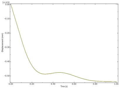
The vertical displacement and landing force due to touch down impact of the nose and main landing gear are obtained in time domain in ABAQUS simulation presented in the Figs. 10-12. The maximum total force of nose landing gear and main landing gears are 10000N and 83000 N obtained in ABAQUS tool almost similar to the responses of SIMULINK analysis results of 9288 N, 90142 N, 90376 N for NLG, MPLG and MSLG as shown in Fig. 7 and Table 3. The little variation in results may be due to the Mathematical Model landing on Grade E random runway. The vertical heave displacement of main landing gears of ABAQUS model is 575 mm and from the mathematical model is 600 mm as in Fig. 8. It is observed that the vertical displacement of the mathematical model solved by Matlab and the ABAQUS multi dynamics model have a close match. The results obtained from the ABAQUS model are similar to numerical simulation of non linear mathematical model in Matlab/Simulink analysis.
Fig. 10Response of main landing gear force (MPLG & MSLG) at sink velocity of 2.5 m/s
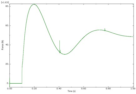
Fig. 11Response of nose landing gear force (NLG) at sink velocity of 2.5 m/s
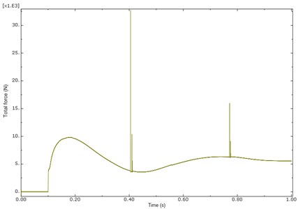
Fig. 12Response of aircraft heave displacement at sink velocity of 2.5 m/s
10. Conclusions
Landing dynamics model of nine degree-of-freedom of aircraft with active landing gears has been developed with the nonlinear spring and damping characteristics. The nonlinear governing equations of motions have been derived and modeled in Matlab/Simulink. The Landing dynamic response of the aircraft as it negotiates different grades of random runways at various sink velocities have been evaluated by numerical simulations. The vibration levels show reduction in the magnitude of aircraft heave, pitch, roll acceleration levels and landing gear forces by the active control system as compared to the passive system during landing over random runway surfaces. It is also observed that the influence of pavement roughness increases the vibration levels and considerably 56 % reduction by active NLG and 20 % reduction by active MSLG and MPLG. In order to validate the nonlinear mathematical model a multi-body dynamics model has been simulated in ABAQUS/CAE and the landing dynamic responses have been obtained compared with those obtained from the nine degree-of-freedom mathematical model. From the dynamic response results presented in this paper, it is observed that the nonlinear mathematical model developed, is a good approximation of the actual aircraft to capture the time response of vibration levels and landing forces estimation during smooth and hard landing. By using the nonlinear mathematical, theoretical evaluation of the nonlinear properties of stiffness and damping curves of landing gear component obtained during drop test can be done. This study is useful in the design spectrum to fine tune the stiffness and damping characteristics of landing gear and to ascertain the vibration levels and landing loads for the development of active landing gear system. The mathematical model can be further used for the longitudinal dynamics. The significant reductions of landing loads and vibrations by the active system increases the life of airframe structure and landing gear while landing on damaged runways.
References
-
T. Catt, D. Cowling, and A. Shepard, “Active landing gear control for improved ride quality during ground roll,” AGARD Smart structures for aircraft and spacecraft, 1992.
-
R. Freymann, “Actively damped landing gear system,” in Landing Gear Design Load Conference, pp. 16–22, 1991.
-
W. E. Howell, J. R. McGehee, R. H. Daugherty, and W. A. Vogler, “F-106B Airplane active control landing gear drop test performance,” in Aerospace Technology Conference and Exposition, No. 21, Sep. 1990, https://doi.org/10.4271/901911
-
N. S. Currey, Aircraft Landing Gear Design: Principles and Practices. Washington DC: American Institute of Aeronautics and Astronautics, 1988.
-
J. Roskam, Airplane Design. Part IV: Layout Design of Landing Gear and Systems. USA: DAR Corporation Lawrence, 1998.
-
T. L. Lomax, Structural Loads Analysis for Commercial Transport Aircraft. Washington DC: American Institute of Aeronautics and Astronautics, 1996.
-
H. Wang, J. T. Xing, W. G. Price, and W. Li, “An investigation of an active landing gear system to reduce aircraft vibrations caused by landing impacts and runway excitations,” Journal of Sound and Vibration, Vol. 317, No. 1-2, pp. 50–66, Oct. 2008, https://doi.org/10.1016/j.jsv.2008.03.016
-
M. Pirooz and M. M. Fateh, “Impedance fuzzy control of an active aircraft landing gear system,” International Journal of Dynamics and Control, Vol. 7, No. 4, pp. 1392–1403, Dec. 2019, https://doi.org/10.1007/s40435-019-00583-0
-
S. Sivakumar and A. Haran, “Mathematical model and vibration analysis of aircraft with active landing gears,” Journal of Vibration and Control, Vol. 21, No. 2, pp. 229–245, Feb. 2015, https://doi.org/10.1177/1077546313486908
-
P. Suresh, N. K. Sura, and K. Shankar, “Investigation of nonlinear landing gear behavior and dynamic responses on high performance aircraft,” Proceedings of the Institution of Mechanical Engineers, Part G: Journal of Aerospace Engineering, Vol. 233, No. 15, pp. 5674–5688, Dec. 2019, https://doi.org/10.1177/0954410019854628
-
Burdzik, Rafal, “Identification of structure and directional distribution of vibration transferred to car-body from road roughness,” Journal of Vibroengineering, Vol. 16, No. 1, pp. 324–333, Feb. 2014.
-
S. Sivakumar and M. Syedhaleem, “Non-linear vibration analysis of oleo pneumatic landing gear at touchdown impact,” Mathematical Models in Engineering, Vol. 4, No. 2, pp. 89–97, Jun. 2018, https://doi.org/10.21595/mme.2018.19895
-
Sharp J. J., Basic Fluid Mechanics. London: Butter worth-Heinemann, 1988.
-
Feng Tyan, Yu-Fen Hong, Shun-Hsu Tu, and Wes S. Jeng, “Generation of random road profiles,” Journal of Advanced Engineering, Vol. 4, No. 2, pp. 1373–1378, 2009.
-
H. Yazici and M. Sever, “Active control of a non-linear landing gear system having oleo pneumatic shock absorber using robust linear quadratic regulator approach,” Proceedings of the Institution of Mechanical Engineers, Part G: Journal of Aerospace Engineering, Vol. 232, No. 13, pp. 2397–2411, Oct. 2018, https://doi.org/10.1177/0954410017713773
-
A. Toloei, E. Aghamirbaha, and M. Zarchi, “Mathematical model and vibration analysis of aircraft with active landing gear system using linear quadratic regulator technique,” International Journal of Engineering, Vol. 29, No. 2, pp. 137–144, Feb. 2016, https://doi.org/10.5829/idosi.ije.2016.29.02b.01
Cited by
About this article

The work presented here is a sponsored research project (ARDB/01/1051911/M/1) funded by the Aeronautics Research and Development Board, DRDO Bhawan, New Delhi, India. Valuable discussions with the Structures panel of the board are gratefully acknowledged.
