Abstract
In this paper, nonlinear vibration analysis of a typical aircraft oleo pneumatic landing gear has been done. Mathematical model of the main landing gear is developed, and dynamic equations have been written incorporating the effect of lift force, friction force to study the landing gear behaviour at touchdown condition. The nonlinear effect of stiffness, damping coefficient properties are considered in the analysis. The displacement, velocity, acceleration values are obtained on different landing velocities by numerical simulations using MATLAB/Simulink. Using the same parameters of the aircraft, landing gear and tire, the dynamic analysis was also done in ABAQUS. The results obtained by the nonlinear vibration analysis using the developed model in MATLAB/Simulink have close agreement with the results obtained from ABAQUS. On the basis of the presented model, dynamic simulations of landing for large transport aircraft were performed for different sink velocities. The developed model is also helpful to fine tune the stiffness and damping properties of landing gear in the design stage itself to reduce the replacement / repair cost and increase the life of landing gear assembly.
1. Introduction
Landing is the most critical operational phase of an aircraft. Landing performance of the aircraft can be directly deteriorated by factors such as excessive sink speed, take off speed, ground effects, crosswind, runway unevenness and pilot errors. Landing gear is the critical assembly of the aircraft that protects the aircraft fuselage from the ground loads. The centre part of the landing gear assembly is called shock strut which plays an important role in absorbing the shocks and vibrations. The aircraft, during its life time, is subjected to varying operating conditions in flight and in the ground. Hence, there is a need to design efficient landing gears. The oleo-pneumatic shock absorber has a high efficiency under dynamic conditions both in terms of energy dissipation and return to normal static conditions [1]. Young [2] presented the development of conventional landing gear with respect to the design, energy absorption characteristics, landing gear geometry and types from 1940 to the present. The books of Currey [3], Roskam [4] are the standard text books which cover the whole conventional landing gear design process including locating the position of landing gear on the fuselage and/or wings, layout of shock absorbers, landing gear operation, kinematic analysis, and the selection of wheels and tires. The telescopic landing gear mathematical model was developed, and nonlinear dynamic equations were presented by Daniels [5] for controlling the landing gear by the hydraulic system externally. Jayarami Reddy et al. [6] presented second order differential equations for oleo pneumatic shock strut describing the non-linear response of a semi levered suspension type of landing gear. Somieski [7] analyzed the shimmy oscillations that are still a problem in the design and operation of landing gears. The linear and non–linear mathematical model for nose landing gear was developed to investigate shimmy vibrations. The British Aerospace funded Shepherd et al. [8] to describe a program for the analysis of aircraft landing gear interaction involving ground contact. A linear six degree of freedom full aircraft model having oleo pneumatic landing gears using PID controller was developed by Sivakumar and Haran [9] to attenuate the ground induced vibrations for passenger and crew comfort and safety while the aircraft is taxiing. Aircraft random vibration analysis has been done by the author [10] for ride comfort on different grades of runways.
Wang et al. [11] modeled a non-linear oleo pneumatic landing gear and used a PID controller to reduce the vibrations caused by runway excitations. Wang et al used non-linearity for landing gear and linear values for tire stiffness and damping coefficients and other researchers mentioned above have done the linear analysis of landing gear with different aircraft landing gear parameters. In the earlier research work by the author, the mathematical modeling of aircraft with active landing gears is formulated to analyze the dynamic response by taking linear values for stiffness and damping characteristics for landing gear system taxiing over discrete and random inputs. In this research work, the nonlinearity curves of landing gear stiffness, damping coefficient and tire stiffness, damping values are considered directly in MATLAB/SIMULINK and also in ABAQUS/CAE. Deflections, velocities and accelerations of a large magnitude can lead to high stress levels in the landing gear as well as in the airframe. Undesirable metal fatigue takes place because of higher vibration levels and it might end in a catastrophic failure of landing gear and airframe structure. The Simulink model of landing gear and approach given in this research is helpful to carry out nonlinear vibration analysis by using experimental inputs and also to fine tune stiffness and damping values of oleo pneumatic landing gear in the initial design stage itself. This will reduce the vibration levels and settling time of the landing gears to increase the life of landing gear and aircraft structure.
2. Oleo pneumatic landing gear
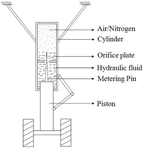
In the oleo pneumatic landing gear, the central part is called shock strut which absorbs shocks during landing. There are two cylinders in the landing gear shock strut. The lower cylinder contains hydraulic oil and high-pressure air/nitrogen is filled in upper cylinder. When the aircraft touches the ground, the hydraulic oil flows from the lower cylinder into the upper cylinder, and this fluid flow is regulated by a metering pin on the piston which goes through an orifice plate in between the upper and the lower cylinders as shown in the Fig. 1. When the shock strut is compressed, the air spring force, damping force and forces due to friction are generated. The impact energy is dissipated during landing through damping while the air spring force gives recoiling effect during ground operation. The total shock absorber force is a combination of air spring force, hydraulic damping force and friction force. A drag strut is fitted to the landing gear for longitudinal stability and a side strut for lateral stability. The torque links are necessary to maintain the alignment of the outer cylinder and inner cylinder or piston. The torque links also prevent the collapse of landing gear during high impact.
3. Non–linear landing gear model formulation
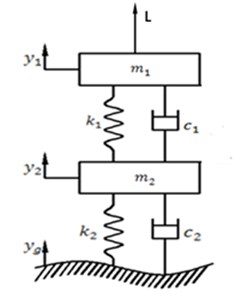
A mathematical model of a main landing gear with the important physical parameters is made. In the mathematical model 40 % aircraft body mass which is acting on one main wheel and upper parts of the landing gear such as outer cylinder, drag-strut, side-strut, orifice plate and metering pin are lumped together as a rigid mass . The mass of the piston axle, wheel, brake and tire components lumped together as a mass . A spring of stiffness and a damper with a viscous damping coefficient are used to represent the shock strut of the landing gear. A spring of stiffness and damping coefficient denotes the tire mass which comes in contact with the runway as shown in the Fig. 1. In the model , are the vertical motion of the masses and respectively. is the ground excitation. The model is assumed to have small motions in the vertical direction. The damper, springs and tire behaviour are considered to be non – linear. In this model tire damping is also considered and the ground contact is maintained. is the aerodynamic lift of the aircraft and is the friction force included in the model. Side loads due to cross wind and other factors are not included in this model. It will be studied separately.
The stiffness and damping properties of landing gear and tire is taken as nonlinear curves that are experimental values of the main landing gear of Fokker aircraft taken from [9]. Non-linear spring stiffness is obtained from air spring force in this system which is a function of relative displacement (stroke) of the piston. The damping coefficient is obtained from the damping force developed by the hydraulic fluid which is a function of the relative velocity (stroke velocity) of the piston.
Fig. 1Oleo pneumatic landing gear and its mathematical model
a)
b)
By Newtonian method, the dynamic equations are written as Eqs. (1)-(4):
The matrix representation of Eq. (2)-(4) becomes:
Eqs. (1)-(3) can be written as state space equations as in Eqs. (6)-(9):
The tire stiffness is given as nonlinear curve [9] and the tire damping coefficient is calculated in Eq. (9) by considering damping ratio 0.1 then:
In this analysis, the typical airplane mass is 22000 kg and the total landing gear mass is 650 kg. Assuming 80 % of total load is shared by two main landing gears and 20 % of load taken by nose landing gear. The main landing gear mass is taken as 8800 kg and the tire mass is 260 kg. In this analysis, only vertical loads are considered, and the side loads due to cross wind and other factors will be investigated separately.
3.1. Estimation of lift
The non-linear analysis of the landing gear is carried out from the point where the aircraft touches down the runway. Since considerable amount of lift is acting on the airplane during touchdown, it has to be accounted in the analysis. To estimate the lift at touchdown, FAR standards for landing have been followed. The nominal touchdown velocity is 1.15 times the stall velocity for a commercial airplane according to FAR standards ( 1.15 ). Once the touchdown velocity is estimated, the lift on the airplane can be calculated using the lift formula given below:
where is the air density, is the planform area of wing and is the coefficient of lift.
At touchdown, the airplane is almost in level with the ground. The lift coefficient for this condition is evaluated by summing up the lift due to the clean wing at this angle of attack and the additional lift obtained by using a high lift device called flap for maximum flap deflection. The angle of attack at touchdown for the same typical airplane can be taken approximately equal to the wing incidence which is 4 deg and the lift coefficient at this angle is 0.35:
The incremental lift coefficient from the flaps is 1.05. Hence, the total lift coefficient at touchdown using Eq. (11) is 1.4. The aircraft stall velocity is 53.65 m/s and the wing planform area is 79 m2. The lift is estimated to be 192015.23 N using Eq. (10). This component of lift acting on one main wheel is 67205.33 N.
3.2. Estimation of friction force
The friction force takes place internally in the piston cylinder arrangement of the oleo pneumatic landing gear. Here, the hydraulic oil acts as a lubricant in between the cylinder and the piston. Assuming the cylinder and the piston to be made of mild steel, the coefficient of kinetic friction between the cylinder and piston in presence of a lubricant is 0.19:
where, is the coefficient of kinetic friction and is the normal reaction. Assuming the offset of the axle length to be negligibly small, the normal force is taken as equal to the ground reaction force on that landing gear that is 86240 N from [9]. The friction force is calculated using Eq. (12) is 16385.6 N.
3.3. Simulation in Matlab/Simulink
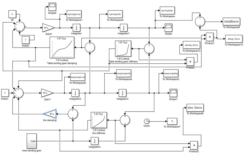
From the dynamic equations, the model of landing gear is developed in Matlab/Simulink. To cater the nonlinear stiffness and nonlinear damping features of the landing gear, the lookup tables are used. Lookup table uses an array of data to map output values to the input values using approximate mathematical functions. One dimensional look up table is used for the nonlinear landing gear spring stiffness, tire spring stiffness and damping and the data is entered with reference to the experimental values from [9]. This will help in non-linear analysis to get the input data for various conditions as Simulink will retrieve the corresponding data from the lookup table. Here the damping model is a function of velocity of the piston. The Simulink model of nonlinear landing gear is shown in Fig. 2.
Fig. 2Simulink model for nonlinear landing gear
The simulation was done with the descent velocity of 2.5 m/s and landing gear touches the runway at 1 s. The maximum displacement of 0.45 m occurs at 1.8 s and settles to 0.40 m of stable position is as shown in Fig. 3. The velocity reaches a maximum of 0.2 m/s and it may be seen that there is an initial deceleration and rebound back to zero position as shown in Fig. 4. The peak acceleration is 1.85 m/s² and the settling time is 2 s from the touchdown as shown in Fig. 5. When the landing gear tire touches the runway at 1 s, the results have shown that there is decrease in acceleration, velocity and displacement and recoil due to the damping characteristics and the oscillations settle at 4 s as shown in Fig. 3-5.
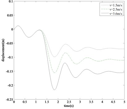
The developed Simulink model is numerically simulated for several trials by taking vertical sink velocity of 1.5 m/s, 2.5 m/s and 3.6 m/s. Results are also plotted for fuselage vertical acceleration and tire mass displacement levels as shown in Fig. 6, 7. It has been noted that response of fuselage acceleration and tire mass displacement increases with increase in sink velocity. It may be noted that a significant rebound occurs following the maximum initial displacement. The acceleration settles at 4 s for all sink velocities. In case of higher sink velocity, the peak acceleration is 2.6 m/s² and the tire mass displacement is 0.22 m as shown in Fig. 6.
Fig. 3Fuselage displacement at a sink velocity of 2.5 m/s
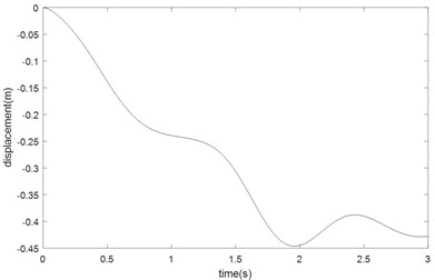
Fig. 4Fuselage velocity at a sink velocity of 2.5 m/s
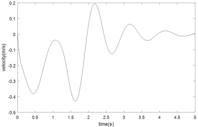
Fig. 5Fuselage acceleration at a sink velocity of 2.5 m/s
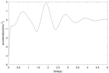
Fig. 6Fuselage acceleration at different sink velocities
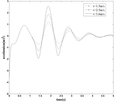
Fig. 7Tire mass displacement at different sink velocities
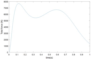
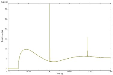
The acceleration values are directly related to the force and moment acting on the fuselage. The displacement response is also related to the ground actions. The shock strut forces are important parameters for estimating fatigue life of the landing gear. The damping force, air spring force and total force developed in landing gear during touchdown impact for sink velocity of 2.5 m/s are shown in Fig. 8-10. The peak damping force is 7800 N and peak air spring force is 3000 N.
Fig. 8Landing gear damping force
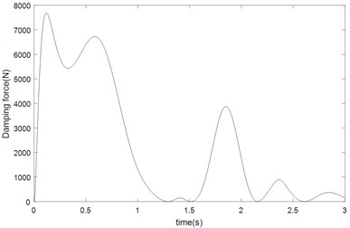
Fig. 9Landing gear air spring force
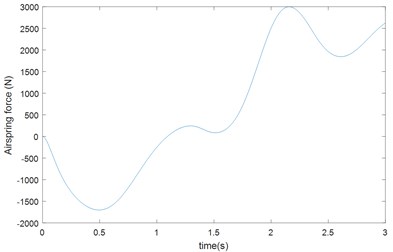
Fig. 10Landing gear total force
3.4. Validation of analysis by ABAQUS
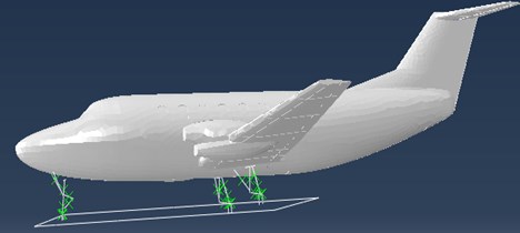
A parameterized modeling approach for analyzing landing gear in ABAQUS/CAE is presented. A conventional aircraft with two main landing gears and a single nose landing gear as shown in Fig. 11. is considered for analysis. The property of stiffness and damping coefficient of main landing gear assigned in ABAQUS are same as that given in the MATLAB/Simulink analysis.
The landing gear is modeled in ABAQUS/CAE as a beam model with the help of geometry using the parameters of the Fokker aircraft landing gear. The multibody is made up of combined rigid and flexible parts in the same model. Rigid bodies are used to represent the components of landing gear with the connector elements. The connector elements provide an easy and versatile way to model physical mechanisms with point to point geometry while still capturing complex kinematic and kinetic behavior. The landing gear is modeled of beam elements and the joints are modeled by join, revolute, cylindrical and other types of connectors. The spring and damper are modeled by a cylindrical type connector that has nonlinear elasticity and damping characteristics. Tires are modeled with connectors that are defined with a stopping behavior that is triggered when the tire comes in contact with the ground. Upon contact with the ground the loads from the aircraft are transferred to the landing gear through the attachment points in the airframe.
Fig. 11Model of a typical aircraft with oleo pneumatic landing gears
The aircraft landing is simulated with a sink velocity of 2.5 m/s on a smooth runway in ABAQUS/CAE. During landing simulation both the main landing gears touch first and the nose landing gear later. The vertical displacement, velocity responses and total force due to touch down impact of the main landing gear using ABAQUS in time domain is presented in the Figs. 12-14. The maximum displacement of ABAQUS model is 520 mm. It is observed that the vertical displacement of the mathematical model solved by Matlab and the ABAQUS multi dynamics model have a close match. The compression pattern of landing gear in ABAQUS model is similar to numerical simulation of vibration model in Matlab. Apart from the displacement, the peak velocity of 0.2 m/s and the total force of the main landing gear obtained in ABAQUS tool is almost similar to the responses shown in the Simulink analysis. Little variation in results may be due to the Multi-Body Dynamics (MBD) model and the Mathematical Model.
Fig. 12Fuselage displacement at a sink velocity of 2.5 m/s
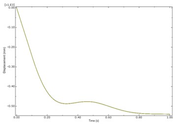
Fig. 13Fuselage velocity at a sink velocity of 2.5 m/s
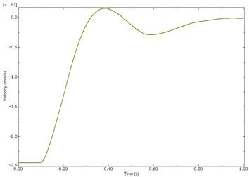
Fig. 14Landing gear total force
4. Conclusions
In this research work, a simple two degree of freedom landing gear model having nonlinear characteristics has been developed in Matlab/Simulink and in order to validate the mathematical model, the dynamic analysis of MBD model of aircraft landing has been done in ABAQUS/CAE. This numerical simulation procedure is helpful to check the vibration levels of aircraft during smooth and hard landing. The fuselage displacement, velocity, acceleration values and total shock strut force obtained by Matlab/Simulink analysis are in reasonable agreement with the results obtained in ABAQUS/CAE analysis. The dynamic responses of landing gear model at different sink velocities show that the system is capable of returning to stable position at a fast rate. The trends of displacement, velocity and acceleration remain similar for all descending velocities. By using this model, the nonlinear properties of stiffness and damping coefficient of landing gear component obtained during drop test evaluated theoretically. This method enables the designer to fine tune the design parameters of landing gear in the initial design stage itself for achieving better performance.
References
-
Jenkins S. F. N. Landing gear design and development. Proceedings of the Institution of Mechanical Engineers, Part G: Journal of Aerospace Engineering, Vol. 203, 1989, p. 67-73.
-
Young D. W. Aircraft landing gears-the past present and future. Proceedings of the Institution of Mechanical Engineers, Part D: Journal of Automobile Engineering, Vol. 200, Issue D2, 1986, p. 75-91.
-
Currey N. S. Aircraft Landing Gear Design: Principles and Practices. AIAA Education Series, AIAA, Washington, 1998.
-
Roskam J. Airplane Design, Part IV: Layout Design of Landing Gear and Systems. DAR Corporation, Lawrence, KS, USA, 1998.
-
Daniels J. N. A Method for Landing Gear Modeling and Simulation with Experimental Validation. NASA CR 201601, 1996.
-
Jayarami Reddy P., Nagaraj Vt, Ramamurti V. Analysis of a semi-levered suspension landing gear with some parametric study. Journal of Dynamic Systems, Measurement, and Control, Vol. 106, 1984, p. 218-224.
-
Somieksi G. Shimmy analysis of a simple aircraft nose landing gear model using different mathematical methods. Aerospace Science and Technology, Vol. 8, 1997, p. 545-555.
-
Sheperd A., Catt T., Cowling D. The Simulation of Aircraft Landing Gear Dynamics. 18th Congress of the International Council of the Aeronautical Sciences, Beijing, China, 1992.
-
Sivakumar S., Haran A. P. Mathematical model and vibration analysis of aircraft with active landing gears. Journal of Vibration and Control, Vol. 21, Issue 2, 2015, p. 229-245.
-
Sivakumar S., Haran A. P. Aircraft random vibration analysis using active landing gears. Journal of Low Frequency Noise, Vibration and Active Control, Vol. 34, Issue 3, 2015, p. 307-322.
-
Wang H., Xing J. T., Price W. G. An investigation of an active landing gear system to reduce aircraft vibrations caused by landing impacts and runway excitations. Journal of Sound and Vibration, Vol. 317, 2008, p. 50-66.
Cited by
About this article

