Abstract
In this paper, the mechanical admittance approach is developed to control a 6 DOF aircraft landing gear. The objective of the control system is improving both passenger comfort (PC) and aircraft handling (AH) which are considered as two important criteria in the evaluation of landing gear systems. A 6 DOF vibrational model and state-space equations are proposed for the system. Then, a control system that is comprised of two loops is proposed. The outer loop is designed for generating a suitable trajectory for body displacement subjected to the tire force. In fact, variable admittance control is used for regulating the dynamical behavior of the system. The other loop is a displacement control loop that used a PD controller to track the generated trajectory. The proposed control system and passive system are both simulated in MATLAB software and the results are compared. The results indicate the effectiveness of the control system in promoting both comfort and handling.
1. Introduction
Landing gear (LG) plays a key role during landing and taxiing in the interaction between runway and aircraft. It provides PC and makes the aircraft to handle on the runway [1]. Until present, a range of control methods is used for controlling the LG. For instance, PID control [2], optimal control [3, 4], back stepping control [5], predictive control [6, 7], and fuzzy control [8-10] are presented by researches. But in these studies, a simple 2 DOF model is used for modeling the LG. In [11, 12] a 6 DOF vibrational model is presented for LG and a PID controller is designed for the active control of LG in which the coefficients are adjusted by Ziegler-Nichols tuning rules. After that, this vibrational model is utilized by other researchers. In some studies, a PID controller was used with variable coefficients. These coefficients can be tuned by intelligent manners such as Bee algorithm, PSO or other methods [13-18].
PC and AH are considered as two opposite criterias for performance evaluation of LG. Major researchers had only focused on the PC and had ignored the handling issues. The behavior of LG is similar to mechanical admittance and impedance. Thus, the admittance control approach can be a powerful method for controlling LG. But the admittance control has not been applied to the LG system in the other researchers’ studies. Hogan introduced the concept of admittance control and impedance control for the first time [19]. These control approaches have been highly considered in robotics researches and are efficient to regulate dynamic behavior of system when interacting with its environment and lead the system to operate as a mass-spring-damper system [20]. The admittance can transform force as its input to displacement as its output and impedance control is a complement of the admittance [19]. The objective of the admittance approach is not controlling the displacement and force separately and it attempts to control the displacement of the system as well as using admittance to regulate the environment force indirectly.
Recently, in order to achieve a reasonable performance including good PC and good AH, an impedance fuzzy controller was proposed for LG. The impedance control system was able to regulate the dynamic behavior of LG [21]. The control system succeeded to decrease the vibrations and improve both PC and AH. However, in this study 2 DOF model was applied and because of the simplicity of the model, the results are not very accurate.
In this paper, first, the 6 DOF vibrational model of LG and space state equation are described. Then, the control system including the admittance control loop and the displacement control loop are designed. In section 4, the proposed control system and passive system are simulated in MATLAB software and the results are compared. The last section is dedicated to the conclusion.
2. Mathematical dynamic model of system
The 6 DOF model of the aircraft’s LG is shown in Fig. 1. These 6 DOFs include vertical displacement of the body , pitch and roll rotations of the body, and three vertical DOFs for three nose , left , and right LGs.
Fig. 1A schematic diagram of 6 DOF vibration model for LG of aircraft [12]
![A schematic diagram of 6 DOF vibration model for LG of aircraft [12]](https://static-01.extrica.com/articles/21221/21221-img1.jpg)
Using Newton-Euler equations, the dynamic equations of the system will be as follows:
In Eq. (1), . The matrix elements of refer to six degrees of freedom which was described previously. In Eq. (1) , and are the stiffness, damping, and mass matrixes which are described in Eqs. (2-4). is the vector forces of LG considered as the input of the system. Also, is the ground input which can be supposed as a kind of external disturbance. is a constant matrix that changes the dimension of :
Considering 12 state variables as , state space equations of the system will be presented as in Eq. (5):
3. Design of control system
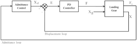
Fig. 2 indicates the block diagram of the control system that includes two interior loops. The outer loop is an admittance loop that adjusts the dynamic behavior of LG. When aircraft is passing a bump, tire force decreases the AH. On the other hand, the ground input decreases the PC. In fact, it is required that a trade-off between PC and AH as two opposite objectives should be found. The relation between the vector of tire forces and the vector of displacements can be predetermined by the impedance rules to achieve the desired behavior. In fact, a suitable trajectory is required for the displacement loop. For providing both PC and AH, finding a reasonable desired trajectory may be difficult. It is better that the desired displacement trajectory be flexible when the tire force faces changes. In this control system, mechanical admittance determines the appropriate desired displacement trajectory according to the tire force. It is able to regulate the interaction between the system and the environment. The inner loop is responsible for controlling position. In order to track the desired position, a PD controller is designed that determines the LG forces according to the error of displacements.
Fig. 2Block diagram of the control system
In order to design a wise desired trajectory for the states, the basics of impedance rules are used in this study. The goal of the controller is to track this trajectory to provide passengers comfort and AH possible, simultaneously. Admittance controller receives the measured tire forces as an input and gives back the displacements as the output. This output is the desired value for the control system and the control system should be able to track it. Tire force is transmitted through the tire from the runway surface and can be described as:
For = 1, 2, 3 the impedance rules for th LG can be proposed as:
As it is obvious in the equation, the impedance rule, for estimating tire force is considered to spot all 12 states of the system. Therefore, all effects of the two other LGs are taken into consideration in the third one. The impedance parameters are selected by the designer based on different conditions. Thus, some of them may be selected as zero.
In order to calculate the outputs, let's rewrite Eq. (7) as follows:
, and are called impedance matrix, desired stiffness matrix, and desired damping matrix, respectively which are time-variant matrices. As is not a square matrix, it is not possible to calculate the inverse of it. In order to extract from Eq. (8), it can be written:
where, is called the admittance matrix that creates a relationship between tire force and desired displacement. The admittance block formulation is clear and it is possible to calculate the states for the desired trajectory. High admittance parameters cause increasing body displacement and decreasing PC. It also leads to decreasing tires’ forces and providing AH. However, selecting low admittance parameters helps to promote PC at the expense of AH. Thus, opting for the admittance parameters depends on runway conditions. If the runway is approximately flat, AH is more prominent while in rough ground PC is a top priority. Thus, a set of reasonable matrices is presented for a variable admittance matrix and each matrix is proportionate to a special condition. They can be chosen by the control system based on which matrix is more suitable. Also, an adaptive admittance matrix can be designed by GA or other artificial intelligence methods.
For controlling the input forces of LG, the PD controllers receive error and its derivate as input and gives back the actuator’s forces. The structure of the controller is designed as:
Eq. (10) can be rewritten as follow:
In order to have a stable closed-loop control system, both admittance and position loops must be stable. To provide an admittance control loop, it's sufficient that be Hurwitz. Every eigenvalue of must possess a strictly negative real part. Also, based on Routh criteria, selecting strictly positive values for and lead to a stable position control loop.
4. Simulation results
The control system is simulated using MATLAB software. The parameters of aircraft used in the simulation are based on [11]. The ground excitations are supposed as:
Fig. 3The response of active and passive systems for different variables
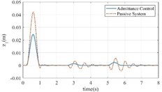
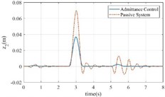
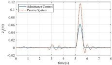
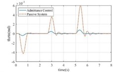
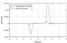
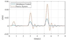
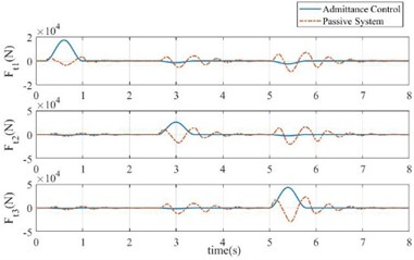
Fig. 4a) Tire forces comparison in both systems, b) the error of the admittance control system
a)
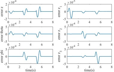
b)
In Fig. 3, the response of the control system and the passive system are compared. In the passive system, vertical and rotational body displacements have huge overshoots and noticeable oscillations. Also, there are large fluctuations and overshoots in the diagrams of the displacements of the nose and main LGs. However, the active system has smoother diagrams with small overshoots and without any oscillations and it arrives to the steady state, quickly.
Also, Fig. 4(a) indicates that the tire forces have several fluctuations and large settling times. Although the peaks in the diagram of the active system have larger values in comparison with the passive system, it has a faster response without fluctuations. Indeed, for providing a suitable PC, the active system prevents large displacements when the aircraft faces the bumps and rapidly reduces tire forces to zero, after passing the bumps to obtain good handling. The tracking errors in closed loop system are observed in Fig. 4(b). The superiority of the control system can be realized by paying attention to the negligible values of the tracking errors.
5. Conclusions
In this study, a new concept is proposed for controlling the landing gear of aircraft. The 6 DOF model of the LG is described and a mechanical admittance control system is proposed for controlling the LG of aircraft subjected to ground inputs. The control system is comprised of two loops. The outer loop is admittance control and regulates the dynamic behavior of the system. The inner loop is displacement control that tracks the desired trajectories generated by the admittance loop using a PD controller. Simulations show that in the proposed admittance control method, the number of oscillations in the graph of body position parameters, and the amplitude of them are reduced significantly, in comparison to the passive system. Moreover, the tire force is highly reduced, which means that the force transmitted to the body of aircraft due to the surfing over bumps, will be declined. As a result, the two important criterias, PC and AH, are increased in this approach. The mechanical admittance approach can be a suitable approach for controlling the landing gear of the aircraft.
References
-
Sancak Ö. F., Güçlü R. Semi active control of fighter jet landing gear comparing with PID and fuzzy logic controller equipped magnetorheological damper. Journal of Engineering and Natural Sciences/Mühendislik ve Fen Bilimleri Dergisi, Vol. 36, Issue 4, 2018, p. 1215-1234.
-
Wang H., Xing J. T., Price W. G., Li W. An investigation of an active landing gear system to reduce aircraft vibrations caused by landing impacts and runway excitations. Journal of Sound and Vibration, Vol. 317, Issues 1-2, 2008, p. 50-66.
-
Mikułowski G., Jankowski Ł. Adaptive landing gear: optimum control strategy and potential for improvement. Shock and Vibration, Vol. 16, Issue 2, 2009, p. 175-194.
-
Toloei A., Aghamirbaha E., Zarchi M. Mathematical model and vibration analysis of aircraft with active landing gear system using linear quadratic regulator technique. International Journal of Engineering-Transactions B: Applications, Vol. 29, Issue 2, 2016, p. 137-144.
-
Zapateiro M., Pozo F., Rossell J. M., Karimi H. R., Luo N. Landing gear suspension control through adaptive backstepping techniques with H∞ performance. IFAC Proceedings Volumes, Vol. 44, Issue 1, 2011, p. 4809-4814.
-
Wu D., Gu H., Liu H. Nonlinear predictive control of semi-active landing gear system. Model Predictive Control, 2010.
-
Wu D., Gu H., Hui L. I. U. GA-based model predictive control of semi-active landing gear. Chinese Journal of Aeronautics, Vol. 20, Issue 1, 2007, p. 47-54.
-
Hui L., Hongbin G., Dawei C. Application of high-speed solenoid valve to the semi-active control of landing gear. Chinese Journal of Aeronautics, Vol. 21, Issue 3, 2008, p. 232-240.
-
Krüger W. Design and simulation of semi-active landing gears for transport aircraft. Chinese Journal of Aeronautics, Vol. 30, Issue 4, 2002, p. 493-526.
-
Saxena D., Rathore H. Vibration control of MR damper landing gear. International Journal of Advanced Research in Artificial Intelligence, Vol. 2, Issue 3, 2013, p. 72-76.
-
Sivakumar S., Haran A. P. Mathematical model and vibration analysis of aircraft with active landing gears. JVC/Journal of Vibration and Control, Vol. 21, Issue 2, 2015, p. 229-245.
-
Sivakumar S., Haran A. P. Aircraft random vibration analysis using active landing gears. Journal of Low Frequency Noise, Vibration and Active Control, Vol. 34, Issue 3, 2015, p. 307-322.
-
Attaran B., Zarchi M. Oscillation control of aircraft shock absorber subsystem using intelligent active performance and optimized classical techniques under sine wave runway excitation. International Journal of Engineering, Vol. 29, Issue 8, 2016, p. 1167-1174.
-
Toloei A. R., Zarchi M., Attaran B. Application of active suspension system to reduce aircraft vibration using PID technique and bees algorithm. International Journal of Computer Applications, Vol. 98, Issue 6, 2014, p. 17-24.
-
Toloei A. R., Zarchi M., Attaran B. Vibration control of aircraft semi-active suspension system using PID-bees technique. International Journal of Computer Applications, Vol. 975, 2014, p. 8887.
-
Toloei A. R., Zarchi M., Attaran B. Numerical survey of vibrational model for third aircraft based on HR suspension system actuator using two bee algorithm objective functions. International Journal of Engineering, Vol. 30, Issue 6, 2017, p. 887-894.
-
Zarchi M., Attaran B. Improved design of an active landing gear for a passenger aircraft using multi-objective optimization technique. Structural and Multidisciplinary Optimization, Vol. 59, Issue 5, 2019, p. 1813-1833.
-
Zarchi M., Attaran B. Performance improvement of an active vibration absorber subsystem for an aircraft model using a bees algorithm based on multi-objective intelligent optimization. Engineering Optimization, Vol. 49, Issue 11, 2017, p. 1905-1921.
-
Hogan N. Impedance control: an approach to manipulation: part II – implementation. Journal of Dynamic Systems, Measurement, and Control, Vol. 107, Issue 1, 1985, p. 8-16.
-
Khalil W., Dombre E. Modeling, Identification and Control of Robots. Butterworth-Heinemann, 2004.
-
Pirooz M., Fateh M. M. Impedance fuzzy control of an active aircraft landing gear system. International Journal of Dynamics and Control, Vol. 7, 2019, p. 1392-1403.
Cited by
About this article

