Abstract
To address the issue of vibration discomfort caused by excessive vibration in the cockpit, a method that allocates vibration reduction index (VRI) to different vibration transfer paths is proposed. By combining the identified vibration contribution of vibration sources using the transfer path analysis (TPA) method with the evaluated relative difficulty levels of vibration reduction design in these paths through the fuzzy analytical hierarchy process, the allocation weights can be constructed, which enables the VRI at the target location can be allocated to these paths, and effective amplitude values of acceleration transferred by these paths can be designed. Then, the specific process of the method is illustrated by a study case on the acceleration designed at the cockpit floor-seat connection. The results show that to achieve a vibration discomfort level that cannot be felt at this location, the effective acceleration amplitudes transferred from the main landing gear compartments and the engines need to be reduced by at least 61.55 % and 77.23 %, respectively. This method can effectively allocate acceleration transferred and guide the cockpit vibration comfort design.
1. Introduction
Air travel has become a popular mode of transportation due to the relatively short time required. And passenger comfort has become a critical factor for choosing airlines, which continuously affects the profits of both airlines and aircraft manufacturers [1]. Therefore, it is essential to establish good comfort in the aircraft design stage.
Passengers' comfort includes vibration comfort and noise comfort [2], and long-term exposure to a vibrating environment can threaten the passengers' health. Therefore, it is necessary to design and evaluate the vibration environment inside the aircraft cabin [3]. However, there is currently a lack of methods for allocating VRI at the target location to these transfer paths.
The vibration transfer can be described as vibration source → transfer path → target location. The frequency-domain contributions from different vibration sources to the target location can be calculated by the TPA method [4]. When the vibration sources are independent of each other, the responses at the target location transmitted from these vibration sources are also independent, resulting in a linear superposition relationship between the square of the vibration value at this location and transferred from different vibration sources. Therefore, the method that assigns the reliability index can be used as a reference [5, 6], which can help establish the method that designs the effective acceleration at the target location from each transfer path.
In this paper, based on the contribution of vibration sources and the difficulty of vibration reduction design in each path, a VRI allocation method is proposed. Firstly, the basic theory of this method is introduced. Then, a study case for cockpit vibration is presented to demonstrate the process of this method, where the required reduction levels of effective acceleration amplitude transmitted by the main transfer paths can be designed.
2. Basic theory
2.1. Analyzing vibration contributions from vibration sources
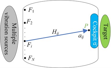
When vibration sources on the aircraft propagate towards the target location in the cockpit, the vibration transfer model is shown in Fig. 1, where the is the target location, and there are vibration transfer paths. According to the TPA method [4], the frequency-domain acceleration at the in the direction () is:
where represents the frequency-domain acceleration transferred from the -th vibration source to , means the transfer function from the -th vibration source to , and represents the frequency-domain load of the -th vibration source.
The frequency-domain acceleration can be converted to its time-domain acceleration through the Fourier inverse transform. Then, according to the weighted frequency curve under 0.5 Hz-80 Hz in the international standard ISO2631-1 [7], the weighted root-mean-square acceleration at can be calculated as follows:
where is the time-domain acceleration of frequency weighted at , and is the duration of the measurement.
The vibration total value (VTV) of the weighted root-mean-square acceleration at is usually inversely proportional to its vibration comfort, and the VTV is given by:
As the mean value of the vibration acceleration is zero, its mean square value is the same as its variance. When various vibration sources are uncorrelation, the VTV at the is the sum of the weighted values from each path. Therefore, the VTV can also be obtained as follows:
where is the time-domain acceleration of frequency weighted at the transferred from the -th vibration source, means the contribution at the from the -th vibration source.
Fig. 1Schematic diagram of the vibration transfer
Therefore, the contribution rate from the -th vibration source can be identified as follows:
If the VTV is greater than the required vibration comfort index , the required vibration comfort level cannot be met. So, the VRI of the ride vibration comfort at the is:
2.2. Designing acceleration transferred by each path
In the vibration reduction design, not only the contribution from each vibration source needs to be considered, but also the difficulty of vibration reduction design in each transfer path. The fuzzy analytic hierarchy process is adopted [8], according to the classification standard in Table 1, multiple relevant experts in the field make judgments on the relative difficulty of vibration reduction design. Thus, a fuzzy judgment matrix can be constructed as follows:
where , , .
After obtaining the fuzzy judgment matrix, it is necessary to construct the fuzzy consistency matrix , whose elements can be constructed as follows:
The relative difficulty level of vibration reduction design for the transfer path from the -th vibration source can be obtained as follows:
where mean inversely proportional to the difference degree in this relative difficulty. In this paper, is taken, which has the highest difference degree.
After normalization, Eq. (9) can be further expressed as:
Then, the allocation weight for the path from -th vibration source to the can be given by:
Therefore, the VRI allocated on this transfer path can be calculated as follows:
The designed effective acceleration amplitude transferred by this path should be reduced by:
Table 1Nine-scale classification standard
Standard | Definition |
0.5 | The difficulty levels of the two compared paths are equal. |
0.6 | In the two compared paths, the former one is relatively easier than the latter one. |
0.7 | In the two compared paths, the former one is significantly easier than the latter one. |
0.8 | In the two compared paths, the former one is clearly easier than the latter one. |
0.9 | In the two compared paths, the former one is extremely easier than the latter one. |
0.1, 0.2, 0.3, 0.4 | The non-difficulty level between factors can be calculated from . |
3. Numerical example
3.1. The VRI to be allocated
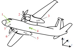
During the initial takeoff stage, the landing gear has been lowered, and the angle of attack, flight speed, and engine power are 0.48°, 61.03 m/s, and 1200 rpm, respectively. The main external vibration sources can be divided into aerodynamic loads and engine excitations. Aerodynamic loads are mainly caused by the nose landing gear compartment (NG), left main landing gear compartment (LG), and right main landing gear compartment (RG). Engine excitations mainly comes from the left engine (LE) and the right engine (RE). The main vibration sources that affect passenger comfort are shown in Fig. 2, where , , and represent the heading, lateral, and vertical directions of the aircraft, and position is the connection between the seat and floor in the cockpit.
In order to simplify the vibration reduction characteristics of the seat and cushion, the is selected as the target location for improving passenger comfort. Assuming that the effective acceleration transmissibility of the seat is 70 %, the required VTV at the is:
where is the VTV at seat surface required by the international standard ISO-2631-1.
According to the international standard ISO2631-1, when the VTV in an exposed vibration environment is less than 0.315 m/s2, it will be at the level of no discomfort. Based on Eq. (14), the required VTV at the is less than 0.450 m/s2. However, the evaluated VTV is 1.8806 m/s2, which is far greater. Thus, according to Eq. (6), the VRI () that needs to be allocated is 3.3342 (m/s2)2.
Fig. 2Main vibration sources of aircraft:1 – cockpit; 2 – LE loads; 3 – LG loads; 4 – passenger cabin; 5 – RG loads; 6 – RE loads; 7 – NG loads
3.2. Vibration contribution from each path
Based on the established and verified full-scale finite element model of aircraft, accelerations at the and the loads satisfy Eq. (1). Under the action of five vibration loads, the frequency-domain acceleration at the in , , and directions from each load can be calculated through LMS virtual lab Software, respectively. Then, their time-domain acceleration can be identified by the Fourier inverse transform. Moreover, according to Eqs. (2)-(5), the vibration contribution of the square of the VTV transmitted from each vibration source to the is shown in Table 2. It can be seen that the VTV is mainly affected by the engine excitations, and the LE has a greater influence. Due to the small contribution of the NG, there are four main vibration transfer paths in the initial takeoff stage, namely LG→P, RG→P, LE→P and RE→P.
Table 2Contribution of vibration source to the P
Contribution | NG→P | LG→P | RG→P | LE→P | RE→P |
/ (m/s2)2 | 0.0004 | 0.1087 | 0.0871 | 1.7757 | 1.5648 |
0.0001 | 0.0307 | 0.0246 | 0.5021 | 0.4424 |
3.3. Assigning reduction level of effective acceleration transferred
20 experts in related fields scored the relative difficulty of the vibration reduction design for the four main transfer paths, and taking the average, the matrix is obtained as follows:
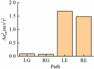
Based on Eqs. (8-10), the relative difficulty vector of vibration reduction design is (0.2367, 0.2367,0.2633,0.2633). Then, using Eq. (11) and the contribution rates in Table 2, the VRI allocation weight vector is (0.0277, 0.0223, 0.5050, 0.4450). Thus, according to VRI and Eq. (12), the VRI allocated to the four main transfer paths are shown in Fig. 3, which are 0.0926 (m/s2)2, 0.0742 (m/s2)2, 1.6837 (m/s2)2, and 1.4837 (m/s2)2, respectively. Most VRI is allocated to the paths from two engines to the P, and the left engine has a slightly higher VRI allocation result. The main reasons are that these engines are the predominant vibration sources, the contribution of the left engine is greater, and the vibration reduction design on these two transfer paths is easier. Moreover, the designed reduction vector of effective amplitude of acceleration transferred is (0.6155, 0.6155, 0.7723, 0.7723). That is, the effective amplitudes of acceleration transmitted from the two main landing gear compartment should be reduced by more than 61.55 %, and the effective amplitudes of acceleration transferred from the two engines need to be reduced by at least 77.23 %.
Fig. 3VRI allocated to main transfer paths
4. Conclusions
In order to solve how to allocate the vibration reduction index (VRI) at the target location to different transfer paths, a VRI allocation method is proposed. The specific process of the proposed method is demonstrated through a study case of cockpit vibration during takeoff. The main conclusions are as follows:
The VRI allocation weight on each transfer path can be determined by combining its contribution identified by the TPA method and the relative difficulty of vibration reduction design in this path evaluated by the fuzzy hierarchy analysis process. Based on this, the VRI can be allocated to each transfer path, and the reduction degree of effective acceleration amplitude transferred through each path can be designed.
The study case shows that in order to meet the vibration comfort level where crew do not feel uncomfortable, the effective acceleration amplitudes transferred from the main landing gear compartments and the engines to the floor-seat connection position need to be reduced by 61.55 % and 77.23 %, respectively.
In this paper, the allocated VRI and the designed reduction degree of effective acceleration transferred by main transfer paths only can be introduced. In subsequent work, specific structures of vibration reduction devices need to be devised to achieve these allocated VRI for improving the cockpit vibration comfort.
References
-
N. Ahmadpour, J.-M. Robert, and G. Lindgaard, “Aircraft passenger comfort experience: Underlying factors and differentiation from discomfort,” Applied Ergonomics, Vol. 52, pp. 301–308, Jan. 2016, https://doi.org/10.1016/j.apergo.2015.07.029
-
A. Brindisi and A. Concilio, “Passengers’ comfort modeling inside aircraft,” Journal of Aircraft, Vol. 45, No. 6, pp. 2001–2008, Nov. 2008, https://doi.org/10.2514/1.36305
-
H. Ciloglu, M. Alziadeh, A. Mohany, and H. Kishawy, “Assessment of the whole body vibration exposure and the dynamic seat comfort in passenger aircraft,” International Journal of Industrial Ergonomics, Vol. 45, pp. 116–123, Feb. 2015, https://doi.org/10.1016/j.ergon.2014.12.011
-
M. V. van der Seijs, D. de Klerk, and D. J. Rixen, “General framework for transfer path analysis: History, theory and classification of techniques,” Mechanical Systems and Signal Processing, Vol. 68-69, pp. 217–244, Feb. 2016, https://doi.org/10.1016/j.ymssp.2015.08.004
-
K. O. Kim and M. J. Zuo, “Optimal allocation of reliability improvement target based on the failure risk and improvement cost,” Reliability Engineering and System Safety, Vol. 180, pp. 104–110, Dec. 2018, https://doi.org/10.1016/j.ress.2018.06.024
-
Y.-C. Chang, K.-H. Chang, and C.-S. Liaw, “Innovative reliability allocation using the maximal entropy ordered weighted averaging method,” Computers and Industrial Engineering, Vol. 57, No. 4, pp. 1274–1281, Nov. 2009, https://doi.org/10.1016/j.cie.2009.06.007
-
“Mechanical vibration and shock-Evaluation of human exposure to whole-body vibration (part 1): general requirements,” ISO 2631-1-1997, International Organization for Standardization Technical Committees, 1997.
-
C. Q. Jia and D. Q. Feng, “Security assessment for industrial control systems based on fuzzy analytic hierarchy process,” Journal of Zhejiang University, Vol. 50, No. 4, pp. 759–765, 2016.
About this article

This research is funded by the projects of CARP (No. 2018F8).
The datasets generated during and/or analyzed during the current study are available from the corresponding author on reasonable request.
The authors declare that they have no conflict of interest.
