Abstract
The cooling of engine piston is very important, and the fluid vibration characteristics of its internal cooling oil is the key to affect the heat transfer efficiency. In order to effectively ensure that the piston temperature will not be overloaded and avoid the reduction of sealing performance, a two-phase flow model in the piston cooling chamber is established in the paper. The flow field and heat transfer characteristics of the cooling oil are simulated by finite element method using FLUENT. In terms of model selection, VOF multiphase flow calculation and SST - model are selected as turbulence model. The setting of boundary conditions combines the piston stroke characteristics of the hydraulic cylinder, so as to obtain accurate inlet parameters, and obtain the oil liquid phase proportion distribution, oil velocity field and the change law of convective heat transfer coefficient under different piston positions. The results show that the instantaneous ratio of cooling oil is closely related to the speed, and increasing the oil speed is an important means to improve the heat transfer performance. The multiphase flow model has high reliability, and there is no obvious difference between the average convective heat transfer coefficient obtained by the near-wall model method and the wall function method.
Highlights
- In order to effectively ensure that the piston temperature will not be overloaded and avoid the reduction of sealing performance, a two-phase flow model in the piston cooling chamber is established.
- The flow field and heat transfer characteristics of the cooling oil are simulated by finite element method using FLUENT.
- In terms of model selection, VOF multiphase flow calculation and SST k-ω model are selected as turbulence model.
1. Introduction
The hydraulic cylinder is an indispensable actuator component in the hydraulic system. The reciprocating movement of the piston in the cylinder can easily cause the oil temperature to be too high. In serious cases, the sealing ring will fail and the distance between the oil molecules will become larger, resulting in bubbles and causing leakage [1]. With the increase of hydraulic driving power, the effective rate and pressure of the piston in the hydraulic cylinder are significantly increased, which makes the temperature in the cylinder prone to large temperature gradient, leading to obvious thermal fatigue and thermal damage of the piston [2-4]. In order to alleviate this problem, a cooling oil chamber can be set in the piston of the hydraulic cylinder to effectively control the temperature distribution of the piston through the circulation of the oil. The improvement of the heat transfer and cooling efficiency of the piston is the hot and difficult point in the research of the engine field.
The cooling chamber of the hydraulic cylinder piston belongs to the typical gas-liquid two-phase mixing state [5]. During the periodic movement of the piston, the ratio of air and oil will change oscillatively [6]. At present, the flow field effect of only one medium is considered in the calculation of single-phase flow, and the intensity and frequency of oscillation are low. According to the structural characteristics of piston cooling oil chamber in hydraulic cylinder, only the method based on two-phase flow calculation can obtain accurate numerical solution. Therefore, based on the finite element analysis method, this paper uses the FLUENT analysis software to study the two-phase flow state and heat transfer characteristics of the cooling oil cavity in the piston of the hydraulic cylinder, providing a basis for the optimization design and performance improvement of the piston.
2. Analysis of flow field in piston cooling chamber of hydraulic cylinder
2.1. Establishment of finite element model
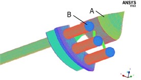
In order to ensure the sealing and lubricity of the sealing ring, the internal and external surfaces of the piston are required to have more rounded corners and sharp corners, which makes the structure of the piston very complex, resulting in great difficulties in finite element analysis. Some small and complex structures have little influence on the calculation results, but they have great influence on the mesh division, convergence verification and calculation efficiency. Therefore, it is necessary to reasonably simplify the piston structure for the analysis of gas-liquid two-phase flow field. According to the actual structural dimensions of the piston, omit the piston rod and relevant accessories, simplify the external round corners and sharp corners, and obtain the three-dimensional model of the piston as shown in Fig. 1. Through the Boolean operation of the model, the fluid model of the cooling oil chamber inside the piston can be obtained, as shown in Fig. 2. Due to the significant symmetry of the model, the 1/4 model of fluid is used for numerical calculation. In order to obtain good mesh quality and reduce mesh distortion, ICEM software is used to mesh the 1/4 model of the fluid. For the small loop structure, the grid is divided in the form of expansion layer. For large surfaces, local encryption is used to ensure the calculation accuracy. Through grid division and adjustment, the final result of grid division is shown in Fig. 3. The total number of cells in the grid is 782560, and the number of nodes is 1602365. According to the grid independence verification, the grid meets the accuracy requirements.
Fig. 1Half piston model
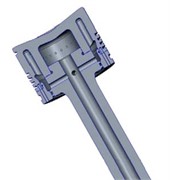
Fig. 2Piston cavity fluid model
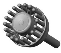
Fig. 3Mesh division of fluid 1/4 model
2.2. Selection of multiphase flow calculation model
In the aspect of numerical research, Euler-Lagrange method and Euler-Euler method are the most widely used multiphase flow calculation methods in engineering. The former method can effectively calculate the discontinuous multiphase flow distribution, especially when the proportion of each phase varies greatly, the calculation accuracy is high; The latter method is more suitable for the flow field analysis of continuous media, and each phase can be processed in the form of fusion. In the FLUENT solver, these two kinds of methods are refined and three solution models are set up: mixed multiphase flow model, Euler multiphase flow model and fluid volume (VOF) model [7].
According to the solution principle, the fluid in the cold chamber of the piston is a typical stratified flow, the gas-liquid phase is not miscible, and the liquid phase proportion is significantly larger than the gas phase. Therefore, the VOF model is selected as the multiphase flow calculation model.
2.3. Three-dimensional steady flow calculation
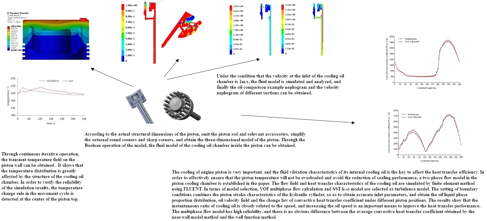
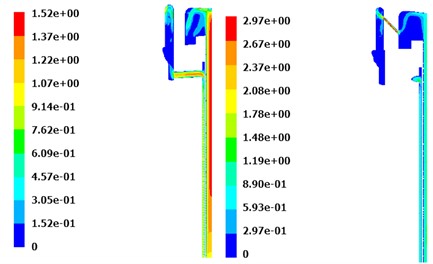
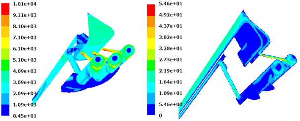
In order to establish the boundary conditions of transient calculation more reasonably, it is necessary to solve the multiphase flow model in a steady state. Although there is a certain deviation between the steady-state solution and the actual boundary conditions, it can effectively obtain the coolant ratio and the movement state of the engine piston under long-term stable working conditions. Under the condition that the velocity at the inlet of the cooling oil chamber is 1 m/s, the fluid model is simulated and analyzed, and finally the oil comparison example nephogram and the velocity nephogram of different sections can be obtained, as shown in Fig. 4 and Fig. 5 respectively.
It can be seen from Fig. 4 that although the inlet flow rate defined by the initial conditions is small, the proportion of oil in the cooling oil chamber is large, and only the front position of the piston top is not full of oil. The design of the cooling ring is relatively reasonable. According to the distribution of the oil proportion, the fillet structure in the oil chamber can be optimized to further improve the utilization of the heat exchange effect of the cooling oil. It can be seen from Fig. 5 that the oil velocity of different sections has great differences, and the maximum velocity is located in the transmission oil passage with the smallest diameter. The speed of oil directly affects the convective heat transfer coefficient. Improving the speed of oil through structural optimization is one of the important means to improve the heat transfer performance.
Fig. 4Oil phase proportion distribution
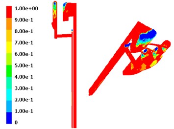
Fig. 5Velocity nephogram of different sections
2.4. Three-dimensional transient flow field calculation
The calculation of the state flow field is more complex than that of the steady state, and requires higher convergence of the model. Set turbulence model type in VOF model for multiphase flow calculation, and select - turbulence model takes the mechanical motion of the engine piston itself as the input source of fluid oscillation. Based on the UDF method, the time domain variation characteristics of inlet velocity are defined. In the process of two-way flow calculation, the analysis of oil ratio does not involve heat exchange, so the energy equation can be closed.
Fig. 6Piston stroke under different crankshaft angular displacement
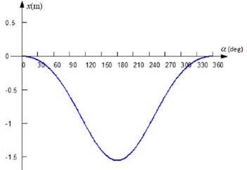
Because the piston has a specific sine motion law, it is necessary to determine the oil supply state according to the moving to the reset position. For the piston with large reciprocating speed, the cooling oil in the cavity will have obvious oscillation phenomenon, and the cooling effect will be more obvious. According to the kinematics characteristics of small gasoline engine piston, the piston stroke under different crankshaft angular displacement is set as shown in Fig. 6, and the piston displacement is in a functional relationship with the fuel supply pressure. During the reciprocating movement of the piston, in addition to the self-excited oscillation of the oil, the oil speed and flow rate at the input end and output end of the piston cooling oil chamber will also be significantly different. Therefore, the flow field in the piston cooling chamber has obvious transient characteristics.
Through continuous iterative operation, the liquid phase proportion distribution at different piston positions can be obtained as shown in Fig. 7. As can be seen in Fig. 7, when the angular displacement of the crankshaft is less than 60°, the speed direction and acceleration direction of the entire piston will not change, but under the action of the relatively high density oil, the piston will move in the opposite direction, at this time, the liquid filling of the oil is relatively large, and only at the end of the ring shows a gas-liquid mixed state. When the angular displacement of the crankshaft is in the range of 90° to 150°, the movement speed of the piston is opposite to the direction of the acceleration. Under the action of the telescopic sleeve of the hydraulic cylinder, the oil speed at the oil input end of the piston cooling chamber decreases until it increases in the opposite direction. At this time, the air ratio increases significantly and enters the cavity at the output end. When the angular displacement of the crankshaft is in the range of 180° to 270°, the piston movement speed and acceleration direction are the same again, and the cooling oil shows a relatively reverse movement trend under the inertial force, which increases the oil velocity at the oil input end. When the angular displacement of the crankshaft is in the range of 300° to 360°, the speed and acceleration direction of the piston movement are reversed again, and the oil moves towards the top of the piston chamber, and the oil proportion at this position increases.
Fig. 7Proportional distribution of liquid phase at different piston positions
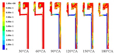
a) 30°-180° crankshaft angular displacement
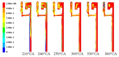
b) 210°-360° crankshaft angular displacement
When the crankshaft angle is 60°, the oil velocity field nephogram of different sections can be obtained as shown in Fig. 8. It can be seen from Fig. 8 that the velocity distribution in this state has obvious matching with the oil ratio, indicating that the two are closely related. Because the piston under this condition tends to move in the opposite direction, the input oil pressure is relatively lower, which shows that the oil velocity gradient is small and the oscillation effect is not significant.
Fig. 8Oil velocity field nephogram of different sections
3. Heat transfer calculation of piston cooling chamber of hydraulic cylinder
3.1. Turbulence model selection
According to the change rule of gas-liquid ratio in the cooling oil chamber of hydraulic cylinder piston, SST - the model simulates and analyzes the heat transfer characteristics of the fluid in the cavity. This turbulence model fully takes into account the compressibility of fluid and the transfer characteristics of shear flow. Compared with other models, it is more consistent with the real boundary. It can not only effectively obtain the change of oil movement rate under free shear conditions, but also contains orthogonal divergence terms in the equation, which can accurately call the wall function, making the difference between the calculation results of the near-wall model and the wall function model smaller. Use SST - Turbulence model is convenient for visual verification, but the calculation speed is relatively slow, and a computer with good performance is required. In addition, to verify the SST - For the calculation accuracy of the turbulence model, different boundary layer models are used to calculate the convective heat transfer coefficient. If the difference between the calculation results of different methods is not obvious, it indicates that the accuracy of the finite element model and the feasibility of the boundary conditions are good.
3.2. Calculation and analysis of convective heat transfer coefficient
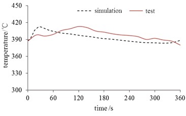
Through continuous iterative operation, the transient temperature field on the piston wall can be obtained as shown in Fig. 9. It shows that the temperature distribution is greatly affected by the structure of the cooling oil chamber. In order to verify the reliability of the simulation results, the temperature change rule in the movement cycle is detected at the center of the piston top, and the verification results are shown in Fig. 10. It shows that the simulation results and test results have good matching, and the numerical simulation results have high accuracy.
Fig. 9Transient temperature field
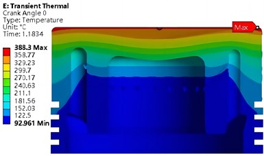
Fig. 10Temperature calibration results
Select the top plane A and B as shown in Fig. 3, and calculate the convective heat transfer coefficient of the selected plane using the near-wall model and the wall function model respectively. The comparison results of the average convective heat transfer coefficient under different boundary layer model conditions are shown in Fig. 11. It can be seen that the calculation results of the near-wall model and the wall function model have little influence on the calculation results of the convective heat transfer coefficient, and the matching degree of the two curves is very high. The forced convection heat transfer effect of plane A and B is good, and the convective heat transfer coefficient is large, but the convective heat transfer coefficient of plane A is significantly smaller than that of plane B. With the increase of the angular displacement of the crankshaft, the fluctuation amplitude of the convective heat transfer coefficient in the B plane is more significant, and the influence of the ratio and speed of the oil cooling oil is more obvious.
In essence, the reference temperature used by the near-wall model in calculating the convective heat transfer coefficient is the average temperature of the entire surface, while the wall function method uses the temperature value of the first grid node. The difference between the two results is very small, indicating that the fluid mixing effect on the surface of the piston cooling chamber is good, making the temperature difference not significant. Plane A and plane B reach the maximum convective heat transfer effect under different stroke states of the piston. When the angular displacement of the crankshaft is greater than 210°, the average convective heat transfer coefficient of different planes has a similar change trend.
Fig. 11Convective heat transfer coefficient of different plane
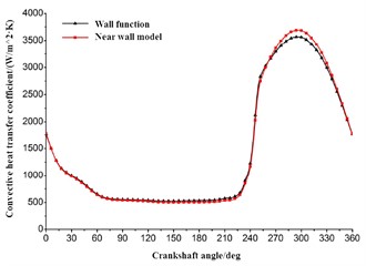
a) Convective heat transfer coefficient of plane A
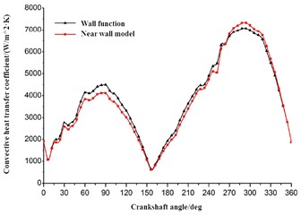
b) Convective heat transfer coefficient of plane B
4. Conclusions
The reciprocating motion of the engine piston produces large heat, and the oil circulation in the piston cooling chamber can effectively carry this heat away, thus improving the piston's ability to resist thermal fatigue. Based on the finite element method, a two-phase flow model in the cooling chamber is established to study the flow field and heat transfer characteristics in the chamber. The following conclusions can be drawn:
1) With the periodic change of piston stroke, the flow field in the cooling chamber is significantly different under different crankshaft angular displacement conditions, the transient characteristics are obvious, and the velocity distribution and the oil ratio have obvious matching, and the two are closely related.
2) According to the calculation of different boundary layer models, the heat transfer effect in the piston cooling chamber is good, and the fluid analysis model established has high accuracy.
References
-
J. Zhou, L. Ma, and Y. K. Yin, “Simulation analysis of piston movement failure of reciprocating pump hydraulic balanced launcher,” (in Chinese), Machine Tool and Hydraulic, Vol. 48, No. 10, pp. 181–184, 2020.
-
C. Dupire et al., “A proof of principle study using radiopharmaceuticals to quantify and localize container-content interactions in medical syringes,” Scientific Reports, Vol. 13, No. 1, pp. 1–9, Feb. 2023, https://doi.org/10.1038/s41598-023-29923-z
-
Z. X. Guan, Y. Cui, and X. J. Zhou, “Analysis and control of engine thermal load based on piston temperature field,” (in Chinese), Automotive Engine, Vol. 51, No. 20, pp. 37–39, 2019.
-
V. E. Scherba and A. V. Grigoriev, “Analysis of efficiency of various methods of compressible gas cooling in piston compressors with variation of key operating parameters,” Chemical and Petroleum Engineering, Vol. 58, No. 7-8, pp. 557–564, Nov. 2022, https://doi.org/10.1007/s10556-023-01129-0
-
Y. H. Zhang and F. Dong, “Study on ultrasonic testing method for void fraction of gas-liquid two-phase flow,” (in Chinese), Telecom Science, Vol. 37, No. 9, pp. 168–174, 2021.
-
A. Jacob, K. Shafi, and K. Reby Roy, “Enhancement of heat transfer in a synthetic jet actuated by piston cylinder,” Advances in Mechanical Engineering, Vol. 13, No. 9, p. 168781402110491, Sep. 2021, https://doi.org/10.1177/16878140211049139
-
L. V. Plotnikov, B. P. Zhilkin, and Y. M. Brodov, “Thermomechanical improvement of gas-air systems of turbocharged piston internal-combustion engines,” Journal of Engineering Physics and Thermophysics, Vol. 93, No. 6, pp. 1557–1566, Nov. 2020, https://doi.org/10.1007/s10891-020-02260-y
About this article

The authors have not disclosed any funding.
The datasets generated during and/or analyzed during the current study are available from the corresponding author on reasonable request.
The authors declare that they have no conflict of interest.
