Abstract
The flow-induced tangential force is crucial for the annular gas seal stability. In this paper, a three-dimensional CFD model is established to study the characteristics of the labyrinth seal. The overall of the seal section is decomposed into each seal cavity. The characteristic of each seal cavity versus rotation speed and inlet pressure is analyzed. The result shows that the sign of in each seal cavity changes from the negative to the positive along the leakage direction, resulting in a specific crossing tooth number at which 0 N. When the tooth number is smaller than , the seal stability increases with the increase of and . When the tooth number is larger than , the trend is reversed. When the tooth number equals , the seal stability is in a critical state, showing no dependency to the and . The is a novel index for the labyrinth seal stability.
1. Introduction
Annular gas seals are key components in turbomachinery to restrict leakage from high-pressure regimes to low-pressure regimes [1]. Its sealing performance direct impacts the unit efficiency. With the development of the modern turbomachinery, the flow-induced vibration caused by seals becomes prominent [2, 3]. The research on the seal stability is important for the stable operation of turbomachinery.
Labyrinth seals (LS) are widely used in turbine machinery due to their low cost, simplicity, and reliability [4]. Extensive research has been conducted on their dynamic performance. Wu and San Andrés [5] compared the rotordynamic force coefficients of a teeth-on-stator LS and an interlocking LS. The result shows that when compared to the interlocking LS, the teeth-on-stator type has a larger effective damping coefficient for operation with whirl frequency up to 30 % above the synchronous rotor speed. Zhang et al. [6] numerically studied the impact of inlet preswirl on the rotordynamic performance of three types of LSs. They found that negative preswirl is beneficial to the stability of LSs. Zhang and Gu [7] proposed a novel anti-stagnation LS with micro-nozzles on adjacent seal teeth. The high-speed jet, driven by the intrinsic pressure difference in the seal domain, is injected into the seal cavity with the direction opposed to the circumferential flow. With controlled circumferential flow, the effective damping coefficient is effectively improved. Sun et al. [8] experimentally studied the impact of a swirl brake on the dynamic performance of LS. The results indicate that the swirl brake effectively reduces the seal swirl ratio, thereby decreasing the destabilizing forces of the seal. Li et al. [9] numerically investigated the effects of operational conditions on the dynamic performance of a teeth-on-stator LS. They found that the magnitudes of all seal force coefficients are roughly proportional to the seal supply pressure but insensitive to the backpressure. Increasing rotation speed and inlet preswirl both result in a significant decrease in effective damping.
The above researches mostly focus on the overall dynamic characteristics of LSs. However, the flow field parameters such as pressure, temperature, velocity, and turbulence intensity vary greatly along the leakage direction. The impact of the flow field parameter differences along the leakage direction on the seal stability is unclear.
In this paper, a three-dimensional numerical model is established to study the flow-induced tangential force characteristics of the LS. The overall of the seal is decomposed into each seal cavity. The characteristic of each cavity versus rotation speed and inlet pressure is analyzed. Based on the characteristics, the conception of the crossing tooth number is proposed as a novel stability index for the labyrinth seal.
2. Numerical method
Fig. 1 shows the schematic diagram of the studied labyrinth seal. Table 1 provides the detailed seal dimensions. The rotor’s eccentric direction aligns with the positive direction of the -axis. When the is in the same direction with the rotor velocity, it is considered a positive value. Conversely, when the force and rotor velocity are in opposite directions, the is considered a negative value. To ensure seal stability, a negative is desired since it removes energy from the forward whirl motion.
Fig. 1Schematic diagram of the studied labyrinth seal
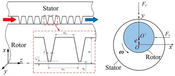
Table 1Seal dimensions
Parameter | Value |
Diameter | 60 mm |
Clearance | 0.2 mm |
Pitch | 3.8 mm |
Cavity height | 3.5 mm |
Tooth thickness | 0.25 mm |
Width of cavity top | 2.3 mm |
Eccentric value | 0.01 mm |
To solve the Reynolds-averaged Navier-Stokes equations, the commercial CFD software ANSYS CFX was used. At the inlet boundary, the total pressure and temperature were defined, while the average static pressure was specified at the outlet. The turbulence model employed was the standard -, with a turbulence intensity of 5 %. The walls of both the rotor and stator were defined as nonslip, and the scalable wall function was applied to control the value of + within 40-100. The target for convergence was set such that the root mean square residuals of the momentum equations, mass equations, energy equations, and turbulence equations were below 10-6 [10, 11]. Table 2 provides the operational parameters for the seals.
Mesh independence studies are performed for the 10-tooth case (8.9 bar, 60 krpm). The is chosen as the evaluation parameter. As shown in Table 3, the of the studied seal shows insensitivity to the increasing mesh density when the element number is larger than 2.4×10⁶ (the difference is within 1.5 % compared with the 5.6×10⁶ case). The mesh density of 2.4×10⁶ elements can meet the mesh independence. Fig. 2 shows final mesh model adopt for the study.
Table 2Operation parameters
Parameter | Value |
Inlet temperature | 287 K |
Inlet pressure | 2.9~8.9 bar |
Outlet pressure | 1 bar |
Inlet preswirl | 0 m/s |
Rotation speed | 0~60 krpm |
Table 3Mesh independence study
Mesh elements | (N) | Difference (%) |
8×10⁵ | –0.109 | 48.1 |
1.6×10⁶ | –0.181 | 13.8 |
2.4×10⁶ | –0.207 | 1.4 |
5.6×10⁶ | –0.210 | 0 (reference) |
Fig. 2Final mesh model adopt for the study
3. Results and discussions
Fig. 3 shows the trend of total flow-induced tangential force versus rotation speed (2.9 bar). The tooth number ranging from 5 to 20 is studied. It can be seen that rotor rotation is the main cause of . As the increase, the magnitude of studied seals all presents an increase trend. As the tooth number increases, the direction of changes from the negative to the positive. For the 5-tooth and 10-tooth cases, the presents the opposite direction to the rotation and the stability increases as the increases. In contrast, for the 15-tooth and 20-tooth cases, the is in the same direction of rotation. The seal stability of 15-tooth and 20-tooth LSs decreases as the rotation speed increases. Notably, for the 14-tooth case, is close to zero at all studied .
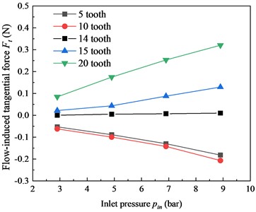
Fig. 4 shows the trend of total flow-induced tangential force versus inlet pressure ( 60 krpm). Similar to the trend of versus shown in Fig. 3, the magnitude of the studied seals also presents an increase trend as the increase. The of the 5-tooth and 10-tooth cases present the opposite direction to the rotation, and the stability increases as the increases. The of the 15-tooth and 20-tooth cases present the same direction to the rotation and the stability decreases as the increases. Similar to the result show in Fig. 3, the of the 14-tooth case is also close to 0 N at all the studied , showing no dependency to the . This phenomenon will be explained in the following section.
It can be seen that there is a crossing tooth number for the LS. When the tooth number is less than , the system stability is positively correlated with the increasing and . When the tooth number is greater than , the system stability is negatively correlated with the increasing and , and the larger the tooth number, the worse the seal stability. When the tooth number is equal to , the total is close to 0 N, showing no dependency to the and . Thus, the labyrinth seal system with different tooth numbers can be divided into the stable and unstable state based on the crossing tooth number . Combining the results from Fig. 3 and Fig. 4, it can be concluded that the of this model is about 14. The 5-tooth and 10-tooth cases are at the stable states, while the 15-tooth and 20-tooth cases are at the unstable state. The 14-tooth case is at the critical stable state.
Fig. 3Total flow-induced tangential force Ft versus rotation speed ω
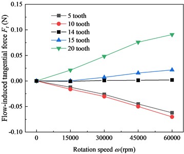
Fig. 4Total flow-induced tangential force Ft versus inlet pressure pin
The above research shows that the total has a close relationship with the tooth number of the LS. For reveal the component, the overall of the seal section is decomposed into each seal cavity. The characteristic of each seal cavity versus rotation speed and inlet pressure is analyzed. Fig. 5 shows the component of each seal cavity under different for 10-tooth and 20-tooth cases (2.9 bar). Along the leakage direction, the of the seal cavity changes from the negative to the positive. For the 10-tooth case, the negative dominates seal section, and the magnitude increases as the increases. This is the reason why the magnitude of the total (negative value) presents the increases trend as the increases shown in Fig. 3. In contrast, for the 20-tooth case, the positive dominates seal section. This explains the reverse trend of the 20-tooth case shown in Fig. 3.
Fig. 5Flow-induced tangential force Ft distribution in seal cavities under different ω
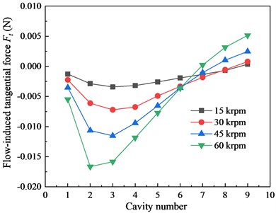
a) 10-tooth
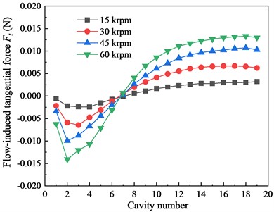
b) 20-tooth
Fig. 6 shows the component of each seal cavity under different inlet pressure for 10-tooth and 20-tooth cases (60 krpm). The effect of inlet pressure is similar to that of the rotation speed. As the increases, the magnitude of negative in each cavity of the 10-tooth case continue to increase. The seal stability is enhanced. For the 20-tooth case, the positive is the main part. Thus, the increasing exerts the negative impact on the seal stability for the 20-tooth LS. The above phenomenon coincides with the results shown in Fig. 4. According to the distribution in seal cavities of the 10-tooth and 20-tooth cases, when the tooth number equals to the 14, the negative and positive of seal cavities cancel each other. This is the reason why the total of the 14-tooth case shows no dependency to the and as shown in Fig. 3 and Fig. 4.
Fig. 6Flow-induced tangential force Ft distribution in seal cavities under different pin
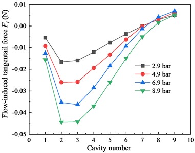
a) 10-tooth
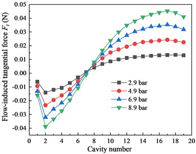
b) 20-tooth
4. Conclusions
In this paper, a three-dimensional CFD model is established to study the flow-induced tangential force characteristics for the labyrinth seals. The overall of the seal section is decomposed into each seal cavity. The characteristic of each seal cavity versus rotation speed and inlet pressure is analyzed. Conclusions are summarized as follows:
1. The total of the labyrinth seal is approximately proportional to the seal supply pressure and rotation speed.
2. The direction of the in the seal cavities changes from positive (near the inlet section) to negative (near the outlet section) along the leakage direction. For labyrinth seals with a small number of teeth, the negative dominates the seal cavities. For those with a large number of seal tooth, the positive plays a more significant role in seal cavities.
3. The labyrinth seal has a crossing tooth number . When the tooth number is smaller than , the is always negative, and the seal stability increases with an increase in rotation speed and inlet pressure. When the tooth number is larger than , the is always positive, and the seal stability is negatively correlated with an increase in rotation speed and inlet pressure. When the tooth number equals , the seal stability is in a critical state, showing no dependency on rotation speed and inlet pressure. is a novel index for evaluating labyrinth seal stability.
References
-
L. Han, Y. Wang, K. Liu, Z. Ban, and H. Liu, “Theoretical modeling for leakage characteristics of two-phase flow in the cryogenic labyrinth seal,” International Journal of Heat and Mass Transfer, Vol. 159, p. 120151, Oct. 2020, https://doi.org/10.1016/j.ijheatmasstransfer.2020.120151
-
Q. Gu, J. Yang, W. Zhang, and M. Zhang, “On the dynamic performance of a novel airfoil guider seal with the controlled circumferential flow: Numerical analysis and experimental validation,” Tribology International, Vol. 167, p. 107413, Mar. 2022, https://doi.org/10.1016/j.triboint.2021.107413
-
M. Zhang and J. Yang, “Spiral flow induced destabilizing force analysis and its reduction with a novel helix-comb gas seal,” Aerospace Science and Technology, Vol. 105, p. 105997, Oct. 2020, https://doi.org/10.1016/j.ast.2020.105997
-
K. Liu et al., “Theoretical and experimental research towards labyrinth sealing mechanism of liquid nitrogen in the cryogenic spindle,” Mechanical Systems and Signal Processing, Vol. 167, p. 108502, Mar. 2022, https://doi.org/10.1016/j.ymssp.2021.108502
-
T. Wu and L. San Andrés, “Leakage and dynamic force coefficients for two labyrinth gas seals: Teeth-on-stator and interlocking teeth configurations. A computational fluid dynamics approach to their performance,” Journal of Engineering for Gas Turbines and Power, Vol. 141, No. 4, p. 42501, Apr. 2019, https://doi.org/10.1115/1.4041123
-
X. Zhang, Y. H. Jiao, X. Q. Qu, Z. Q. Zhao, G. H. Huo, and K. Huang, “Inlet preswirl dependence research on three different labyrinth seals,” Tribology International, Vol. 176, p. 10792, 2022, https://doi.org/10.1016/j.triboint.2022
-
W. Zhang, Q. Gu, and T. Wang, “Study on the rotordynamic performance of a novel anti-stagnation labyrinth seal,” Journal of Vibration Engineering and Technologies, Vol. 8, No. 6, pp. 835–846, Dec. 2020, https://doi.org/10.1007/s42417-019-00191-4
-
D. Sun, S. Wang, C.-W. Fei, Y.-T. Ai, and K.-M. Wang, “Numerical and experimental investigation on the effect of swirl brakes on the labyrinth seals,” Journal of Engineering for Gas Turbines and Power, Vol. 138, No. 3, p. 03250, Mar. 2016, https://doi.org/10.1115/1.4031562
-
Z. Li, J. Li, and Z. Feng, “Labyrinth seal rotordynamic characteristics part I: operational conditions effects,” Journal of Propulsion and Power, Vol. 32, No. 5, pp. 1199–1211, Sep. 2016, https://doi.org/10.2514/1.b35816
-
Q. Gu, J. Yang, W. Zhang, and M. Zhang, “An accelerating sweep frequency excitation method for the rotordynamic coefficients identification of annular gas seals based on computational fluid dynamics,” Journal of Engineering for Gas Turbines and Power, Vol. 143, No. 9, p. 09102, Sep. 2021, https://doi.org/10.1115/1.4051101
-
W. Zhang, Q. Gu, J. Yang, and C. Li, “Application of a novel rotordynamic identification method for annular seals with arbitrary elliptical orbits and eccentricities,” Journal of Engineering for Gas Turbines and Power, Vol. 141, No. 9, p. 09101, Sep. 2019, https://doi.org/10.1115/1.4044121
About this article

The authors are grateful for the Grants from the National Natural Science Foundation of China (52075096).
The datasets generated during and/or analyzed during the current study are available from the corresponding author on reasonable request.
The authors declare that they have no conflict of interest.
