Abstract
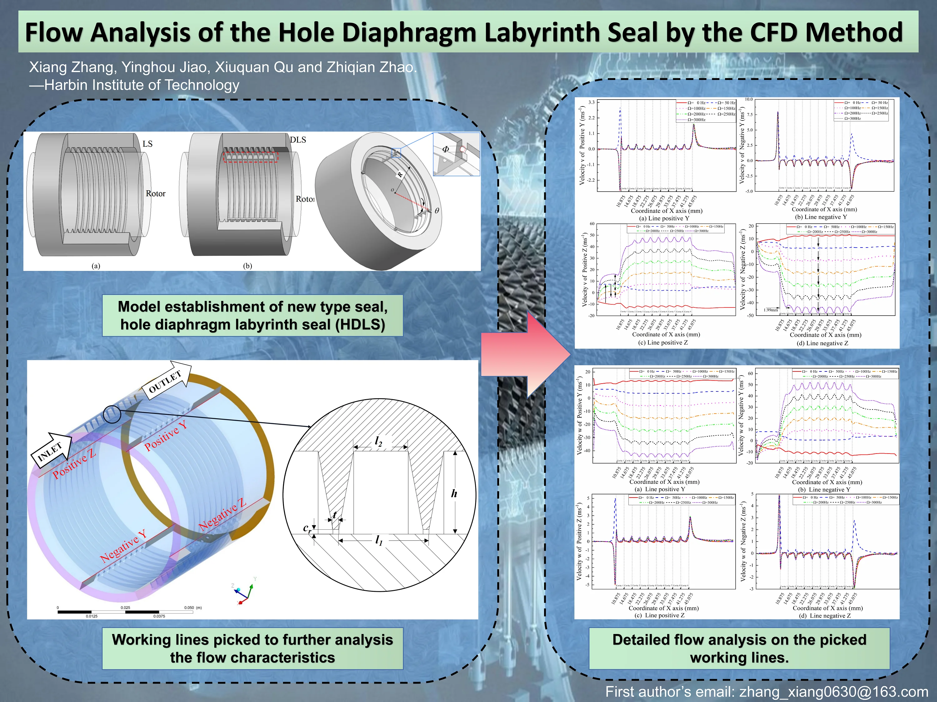
The computational fluid dynamics (CFD) method is an efficient way to reduce the obstacles in fluid studies. Good use of the CFD method on the seal-rotor system area was proven again in this paper. The flow analyses of a new type of annular seal, the hole diaphragm labyrinth seal (HDLS), were studied by Fluent. Complex working conditions were considered to further understand the flow field variation trend. The results show that the maximum velocity component was obtained in the middle cavities perpendicular to the whirl direction. The velocity distributions before the first cavity and behind the last cavity show a different trend under a 50 Hz whirl frequency than that of other whirl frequencies, which can be described by the most apparent throttling effect of the first blade and the diffuse effect behind the last blade. It is helpful to further understand different annular seal characteristics by detailed fluid information analyses.
Highlights
- New type of labyrinth seal, which can be used in steam and gas turbines, was proposed.
- Detailed flow analysis method was used to further understand the working characterstics.
- Abnormal velocity component was observed at particular working conditions.
1. Introduction
It is important to use seals to reduce leakage in gas turbines and steam turbines. The Labyrinth seal (LS) is an annular seal that is widely used for its simple structure. Traditional LS designed by a group of blades on the straight stator. The core physical mechanisms used in LS are the throttling effect between the tip of the blade and rotor surface and the vortex dissipation effect in the seal cavity.
Many studies have been conducted by scholars over the past several tens of years. Li [1] discussed the rotordynamic performance between diverse labyrinth seals, whose teeth are designed on distinct components, by the transient computational fluid dynamics (CFD) method. The advantages on leakage were found in the interlocking-tooth labyrinth seal, while the dynamic performance was also better than that of the tooth-on-rotor labyrinth seal. Similar research was studied by Savvakis [2] using the CFD method. Flow field performance under different radial clearances and tooth locations of the LS was studied by Čížek [3]. Static pressure, total temperature, total enthalpy, flow coefficient, density and kinetic energy values were compared between different clearances conditions.
A damper seal, a fully partitioned damper seal (FPDS), was designed by Li [4]. The circumferential lengths of the pockets in FPDS are basically equal, while the radial cavity lengths are periodically different. The static pressure contours of the FPDS show richer change rules than those of the LS, which results in a better frequency dependence. Fig. 1 shows the diagrams of two different labyrinth seals. Fig. 1(a) is a traditional LS, while Fig. 1(b) presents a kind of diaphragm labyrinth seal (DLS) with equal cavities, which is similar to FPDS. The difference between DLS and FPDS is that the radial cavity length is equal for DLS.
Another kind of damper seal is the honeycomb shroud seal, which combines the honeycomb seal and labyrinth seal. Yan [5] compared the leakage and flow angle between honeycomb seal, hole-pattern seal and labyrinth seal. Streamline analysis was used to study the secondary flow developments of different seals and clearance conditions using the CFD method. A similar study was conducted by Wróblewski [6]. Furthermore, visualization by the particle image velocimetry (PIV) method was studied by Denecke [7], which can directly observe the flow information.
In this paper, a new labyrinth seal is presented. A series of simulations of a new kind of hole diaphragm labyrinth seal was performed by ANSYS Fluent. Velocity component changes on picked line directions were discussed under different working conditions.
Fig. 1Diagrams of two different labyrinth seals: a) traditional labyrinth seal (LS); b) diaphragm labyrinth seal (DLS, designed with four groups of diaphragms on the circumferential direction of a traditional LS)
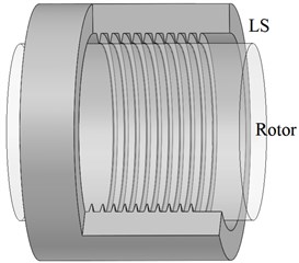
a)
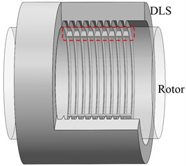
b)
2. Model establishment
A new kind of labyrinth seal, the hole diaphragm labyrinth seal (HDLS), can be obtained by combining the traditional LS and DLS. The diagram and cross-sectional view of HDLS are shown in Fig. 2 and Fig. 3. Fig. 2 shows the four picked lines that can be used to analyse the flow characteristics. The design parameters, which are marked in Fig. 2 and Fig. 3, are listed in Table 1.
Simulation works in this paper were calculated in ANSYS Fluent. Detailed calculation conditions are listed in Table 2.
Fig. 2Diagram of the hole diaphragm labyrinth seal
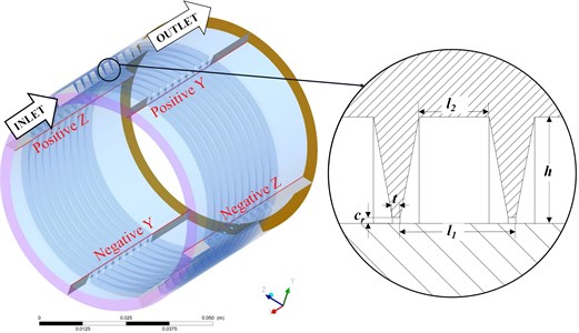
Table 1Design parameters of HDLS
Parameter name | Values |
Rotor radius / mm | 30 |
Radial clearance / mm | 0.2 |
Cavity depth / mm | 3.5 |
Cavity width / mm | 3.8 |
Blade thickness / mm | 0.25 |
Blade space width / mm | 2.3 |
Diaphragm width / ° | 2 |
Diagram of holes / mm | 1 |
Number of blades | 10 |
Fig. 3V-direction velocity curves
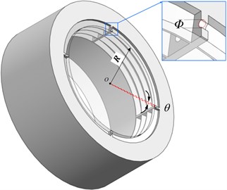
Table 2Calculation conditions
Parameters’ name | Values |
Turbulence model | Standard - |
Inlet pressure / MPa | 0.69 |
Outlet pressure / MPa | 0.1 |
Whirl radius rate / % | 5, 10, 15, 20, 25 |
Whirl frequency / Hz | 0, 50, 100, 150, 200, 250, 300 |
Rotation speed / rpm | 1000, 5000, 10000 |
Maximum flow difference / | 0.01 |
Residual control | ≤ 10-6 |
3. Results and discussions
A series of simulations were calculated under the working conditions listed in Table 2. The leakage performance and turbulence characteristics were already studied by the authors [8]. However, this new structure presents a promising advantage in the fluid seal area, which needs further research. The detailed velocity values on the considered lines can be obtained by reprocessing.
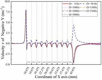
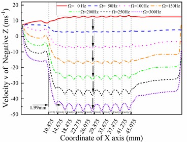
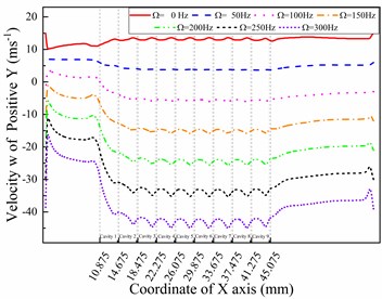
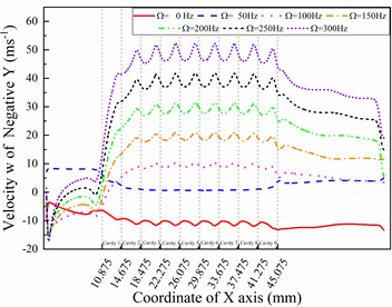
The coordinate system corresponds to the coordinate system in the CFD-POST, which is used to obtain calculated values. Fig. 4 shows the velocity components in the v-direction under different whirl frequencies. The differences between Fig. 4(a) and 4(b) show that special velocity components were observed in the positive and negative directions under a 50 Hz frequency and 5000 rpm rotation speed. The rotation speed of the rotor surface is lower than that of the positive position, which causes the low pressure area to appear on the surface of the sealing cavity. It is obvious that the direction of velocity v exhibits a reversal in cavity 1, which describes the phenomenon that the direction of the relative speed between the rotor and the seal changes here. Another obvious phenomenon is that the velocity component in the -direction reached the maximum at the first blade position on the positive and negative lines, while the second largest value was at the last blade position. Such a phenomenon cannot be found in the velocity v components of the directions, which are shown in Fig. 4(c) and 4(d). Fig. 4(c) clearly shows how the whirl frequency affects the circumferential flow velocity in the seal cavities. The velocity components show a different changing trend before the first cavity increases at 50 Hz, then decreases at 100 Hz and then keeps increasing with increasing whirl frequency; however, it keeps increasing in the second and following cavities. A similar monotonous change trend can also be found in Fig. 4(d). The velocity components in the directions reach maximum values in cavity 5 and cavity 6, which is different from Fig. 4(a) and 4(b). Moreover, the distance between the previous blade and the maximum absolute value reaches 1.99 mm, while the cavity length is 3.3 mm. The velocity of the working medium increases to the maximum in the front 60 percent distance of the cavity behind each blade because of the jet effect and expansion effect.
Fig. 4V-direction velocity curves in different directions with different whirl frequencies (ω= 5000 rpm)
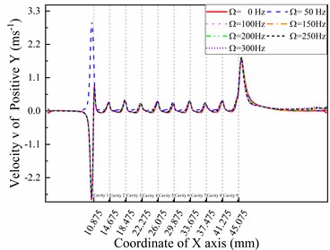
a) Line positive
b) Line negative
c) Line positive
d) Line negative
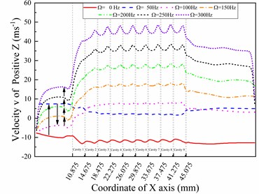
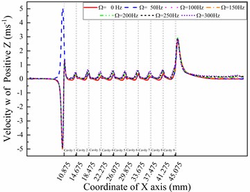
Fig. 5W-direction velocity curves in different directions with different whirl frequencies (ω= 5000 rpm)
a) Line positive
b) Line negative
c) Line positive
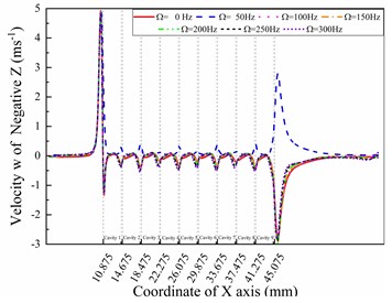
d) Line negative
Fig. 5 shows the velocity components in the -direction under different whirl frequencies. A similar phenomenon in the v-direction can also be found in the -direction, which is the opposite of the -direction. Comparing the tangential velocities in Fig. 4 and Fig. 5, which are velocity of the -direction line and velocity of the -direction line, the values at the end boundary of cavity 1 in Fig. 4(d) changed more quickly than those in Fig. 5(a). This phenomenon shows that the height of the near-wall layer decreases in the -direction because the eccentric distance is fixed in the positive direction in this paper. Meanwhile, the larger decrease in velocity values shown in Fig. 5(a) cannot be observed in the positive direction behind the last fin compared with Fig. 4(c), 4(d), and 5(b), which also provides for the above analysis. The trends in Fig. 5(c) and 5(d) are the same as those in Fig. 4(a) and 4(b), while the only difference is that the maximum value decreases on positive while increasing on negative . The reason for these differences is that the -direction is perpendicular to the -direction.
4. Conclusions
In this paper, the detailed flow information of a hole diaphragm labyrinth seal (HDLS) was studied by the computational fluid dynamics (CFD) method. Different working conditions, such as the whirl frequency, rotation speed and whirl radius rate, were discussed. The calculated lines, which are under different circumferential positions, were picked to further understand the flow characteristics in the HDLS. The results show that the maximum velocity component was obtained in the middle cavities perpendicular to the whirl direction. Special velocity values were observed at a 50 Hz whirl frequency, which can be described by the radial velocity gradient that causes the pressure gradient in a small area. Meanwhile, the comprehensive analysis of velocity components among different circumferential positions indicated that the height of the near wall layer depended on the clearance of the flow section. Detailed analysis of flow characteristics can provide further understanding of complex fluid machines. This paper is useful for researchers who focus on gas turbine and steam turbine areas to further understand the working mechanism of fluid seals.
References
-
Z. Li, J. Li, and Z. Feng, “Numerical comparisons of rotordynamic characteristics for three types of labyrinth gas seals with inlet preswirl,” Proceedings of the Institution of Mechanical Engineers, Part A: Journal of Power and Energy, Vol. 230, No. 7, pp. 721–738, Nov. 2016, https://doi.org/10.1177/0957650916668768
-
S. Savvakis, D. Mertzis, E. Nassiopoulos, and Z. Samaras, “A design of the compression chamber and optimization of the sealing of a novel rotary internal combustion engine using CFD,” Energies, Vol. 13, No. 9, p. 2362, May 2020, https://doi.org/10.3390/en13092362
-
M. Čížek, Z. Pátek, and T. Vampola, “Aircraft turbine engine labyrinth seal CFD sensitivity analysis,” Applied Sciences, Vol. 10, No. 19, p. 6830, Sep. 2020, https://doi.org/10.3390/app10196830
-
Z. Li, J. Li, and X. Yan, “Multiple frequencies elliptical whirling orbit model and transient rans solution approach to rotordynamic coefficients of annual gas seals prediction,” Journal of Vibration and Acoustics, Vol. 135, No. 3, Jun. 2013, https://doi.org/10.1115/1.4023143
-
X. Yan, X. Chen, and K. He, “Influence of shroud seal dimensions on aerodynamic performance of steam turbine stages: part I – honeycomb seal,” in ASME Turbo Expo 2016: Turbomachinery Technical Conference and Exposition, Jun. 2016, https://doi.org/10.1115/gt2016-56917
-
W. Wróblewski, D. Frączek, and K. Marugi, “Leakage reduction by optimisation of the straight-through labyrinth seal with a honeycomb and alternative land configurations,” International Journal of Heat and Mass Transfer, Vol. 126, pp. 725–739, Nov. 2018, https://doi.org/10.1016/j.ijheatmasstransfer.2018.05.070
-
J. Denecke, V. Schramm, S. Kim, and S. Wittig, “Influence of rub-grooves on labyrinth seal leakage,” Journal of Turbomachinery, Vol. 125, No. 2, pp. 387–393, Apr. 2003, https://doi.org/10.1115/1.1539516
-
X. Zhang, Y. Jiao, X. Qu, G. Huo, and Z. Zhao, “Simulation and flow analysis of the hole diaphragm labyrinth seal at several whirl frequencies,” Energies, Vol. 15, No. 1, p. 379, Jan. 2022, https://doi.org/10.3390/en15010379
About this article

This work was supported by the National Natural Science Foundation of China (No. 12072089, No. 11972131) and the National Science and Technology Major Project (2017-ⅠV-0010-0047).
