Abstract
Introducing a negative preswirl at the upstream of annular gas seals has been considered as an effective way to improve the system stability. This paper demonstrates a stability enhancement approach for a short labyrinth seal using positive preswirls. The static and dynamic characteristics of the labyrinth seal with various blade numbers (5, 10, 15), inlet preswirl ratios (–0.3, –0.15, 0, 0.15, 0.3) were studied. Results show that the inlet preswirl ratio has a dramatic effect on the circumferential location of the high-pressure spot for each seal cavity, particularly for the first cavity. The inlet preswirl ratio has opposite effects on the system stability due to the difference of high-pressure spot locations between the first cavity and the others. An increasing positive inlet preswirl could improve the system stability for the labyrinth seal with fewer blades (e.g. 5 blades). Its characteristics is mainly dominated by the first seal cavity. For the labyrinth seal with 10 blades, the system characteristics shows slight dependency on the inlet preswirl ratio. For the labyrinth seal with more blades (e.g. 15 blades), the negative inlet preswirl still increases the system stability, which agrees with the conventional conclusion. The paper provides a deeper understanding on the stability improvement of the labyrinth seal.
Highlights
- A stability enhancement approach for a short labyrinth seal could be realized by using positive preswirls.
- Inlet preswirl ratios has opposite effects on the system stability due to the difference of high pressure spot locations between the first cavity and the others.
- For the labyrinth seal with some centain blades, the system characteristics shows slight dependency on the inlet preswirl ratio.
1. Introduction
Labyrinth seals are used extensively in turbomachines to minimize the leakage flow rate by separating high pressure fluid from entering into a low-pressure region. Moreover, the rotor stability is threatened by the labyrinth seal due to the driving forces generated in the seal cavity [1]. Proposing effective approaches to improve the dynamic stability of labyrinth seals is crucial for the safety and stable operation of turbomachines [2].
Instability phenomenon resulting from labyrinth seals was reported firstly by Den Hartog [3] in 1950s. Then Thomas [4] presented a physical explanation of the occurrence of self-excited vibrations through clearance flows at the blade tips and inter-stage glands. In 1965, Alford [5] put forward the occurrence of a circumferential variation of static pressure acting on the cylindrical surface of a rotor particularly within labyrinth seals, which results in the aerodynamic exciting force on jet turbo compressors and turbines. It was concluded that unequal radial clearances at the entry and discharge have a significant effect on the excitation. However, the rotational motion of the rotor was neglected in the stability analysis. In 1974, Rosenberg et al. [6] indicated that lateral forces can be produced due to the inlet preswirl and rotating surface in case of parallel clearances when an eccentricity exists with or without the occurrence of spiral flow. Until 1970s-1980s, lots of analytical work [7-11] and experimental measurements [12-14] were consecutively carried out to predict the leakage flow rate, circumferential flow, pressure distribution qualitatively.
To suppress the circumferential velocity component and improve the rotordynamic characteristics of labyrinth seals, two methods are generally used. The first approach is setting up swirl brakes at the upstream of the seal. The second one is utilized by means of shunt injection. Circumferential flows [12, 15, 16] due to swirl brakes, shunt injection, circumferential entry velocity, and rotational shaft surface at the seal inlet have a significant effect on the system stability. It can be usually categorized into zero, positive, negative preswirl in terms of the circumferential entry direction.
In 1980, Benckert and Wachter [12] firstly reported that the inlet flow direction of the seal in the same direction of shaft rotation would destabilize the rotor-seal system, while the reversing preswirl at the seal inlet can effectively improve the stability by offsetting the circumferential flow. This phenomenon has drawn many research attentions on the negative preswirl. In 1986, Kirk [17] firstly studied the effect of the reverse jet (shunt injection) on unstable compressors and successfully overcame the subsynchronous vibration of centrifugal compressors. In 1990s, Memmott [18, 19] employed a shunt injection method to solve problems of subsynchronous vibrations of high-parameter centrifugal compressors. Shunt injection has proven to be dynamically beneficial in many cases [20], but there have been some cases in which they were not satisfactory. In 1999, Soto and Childs [21] experimentally studied the effect of shunt injection on the dynamic characteristics of a 20-tooth labyrinth seal by removing the fourth tooth. The effects of pressure ratio, rotational speed and injection direction (radial and against rotation) on seal stability were compared. It is found that the jet against rotation can effectively reduce the cross-coupled stiffness coefficient under various operating conditions and improve the effective damping of the labyrinth seal. However, a 100 % increase in the leakage flow rate was found for measured cases due to the presence of shunt injection. In 2003, Kim et al. [22] developed a quasi three-dimensional CFD perturbation model for a 19-tooth labyrinth seal with shunt injection at any axial location. The axial location of the injection appears to have only a slight effect on rotordynamic stability for the considered cases. In 2007, Gans [23] presented the effects of reversed-swirl brakes in a combined labyrinth-brush seal. The reversed-swirl brakes are intended to induce fluid rotation against shaft rotation and reduce the destabilizing effects of a combined labyrinth-brush seal. In 2012, Brown and Childs [24] investigated the rotordynamic coefficients for a hole-pattern seal with negative preswirl. Results show that the negative preswirl could reverse the sign of cross-coupled stiffness coefficients and significantly increase the effective damping coefficient. In 2016, Childs et al. [25] studied rotordynamic performance of negative-swirl brakes for a 16-tooth labyrinth seal using both prediction and experimental measurements. The negative-swirl brake produces a change in the sign of the cross-coupled stiffness coefficient with an appreciable magnitude, and the stability of forward precessional modes would be enhanced. In 2018, Untaroiu et al. [15] studied on the geometry of negative-swirl brake in order to suppress the circumferential flow and improve the stability of a 16-tooth labyrinth seal more effectively.
Published literatures demonstrated that the pre-rotation into a labyrinth seal in the direction of the rotor rotation generally creates a positive cross-coupled stiffness that would destabilize a rotor. Similarly, the pre-rotation against the direction of shaft rotation produces a negative cross-coupled stiffness coefficient that would stabilize the rotor. Note that the circumferential pressure distribution in the seal cavity could be different from that in the oil film of journal bearings. A high-pressure spot always appears in the circumferential convergent-clearance for a journal bearings. However, the high-pressure spot in the labyrinth seal may vary for each seal cavity. Some static instability phenomena [26, 27] indicate the high-pressure spot appears in the circumferential divergent-clearance of the seal cavity. Rare publications study the detailed pressure distribution for each seal cavity and discuss the contribution of each seal cavity on the overall stability, particularly for a short seal including few teeth working with preswirls. It is of interest to further study the rotordynamic performance of the labyrinth seal considering different preswirls.
This research investigates the effects of two negative preswirls, zero preswirl, two positive preswirls on the seal reaction force of each seal cavity and rotordynamic coefficient for a short labyrinth seal. Three-dimensional flow in the short labyrinth seal is simulated by solving the Reynolds-averaged Navier-Stokes (RANS) equations in a commercial software [28]. The circumferential pressure distribution for each cavity is analyzed for various whirling frequencies. The static and dynamic force coefficients are further investigated to evaluate the stability characteristics.
2. Rotordynamic model of the labyrinth seal
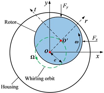
Fig. 1 depicts the rotordynamic model for annular gas seals. In the coordinate system (, ), is the stator center, is the rotor center. , denote the tangential and radial direction, respectively. The whirling orbit of the rotor can be approximately assumed as a cycle with a radius [29]. The rotational and whirling speed are , , respectively. The seal reaction force can be divided into two components, , in two orthogonal directions.
Fig. 1Rotordynamic model for annular gas seals
According the first-order perturbation of the bulk-flow governing equations by Childs [1, 30], the seal reaction force is significantly more linear function of displacement than bearings. The linearized force-displacement model for seals can be stated as:
Under small perturbations about a centered position, the seal reaction force for a gas seal can be expressed by Eq. (2):
Generally, the direct stiffness coefficient influences the system stiffness and critical speed of the rotor system. The tangential force characterized by the cross-coupled stiffness coefficient is a major contributing factor to the nonsynchronous whirl. The direct damping coefficient reflects the capacity to suppress the unstable whirling motion. An increase of is benefit for the system stability. The cross-coupled damping coefficient is insignificant to the rotor seal system.
The moving reference frame (MRF) [31] is employed to identify the dynamic characteristics of the annular seal. As shown in Fig. 2, when the rotor motion is observed from a stationary frame of reference, the relative position of rotor and stator seems to be changing all the time. Therefore, the moving grid and transient analysis are necessary. From a moving frame of reference with , the rotor becomes to be a relatively stationary position. In this case, the analysis can be simplified as a steady state problem. Compared with the transient analysis, MRF method could save more computing resources with finer mesh grids. Particularly, this method is suitable for the analysis of the labyrinth seal [31].
Fig. 2Schematic diagram of the quasi-steady state model
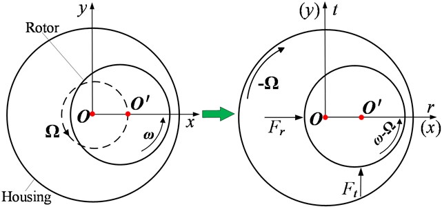
The orbit equation of the whirling rotor in the (, ) coordinate system is defined by Eq. (3):
In the rotating coordinate system, the radial component and the tangential component of the seal reaction force acting on the rotor can be expressed as Eq. (4):
Eq. (4) shows that the radial force and tangential force are composed of stiffness and damping terms. When the whirling frequency equals to 0 Hz, only the stiffness term plays a role. The cross-coupled stiffness coefficient can be expressed as Eq. (5):
3. Numerical method
3.1. Geometrical parameters
Fig. 3 shows the cross section of the test labyrinth seal. Table 1 gives its detailed dimensions. The test seal includes 10 blades and 9 cavities (#1~#9). In order to study the effect of the blade number on the dynamic characteristics, the labyrinth seal with 5 and 15 blades are also employed in the numerical simulation.
Fig. 3Two-dimensional geometry of the test labyrinth seal
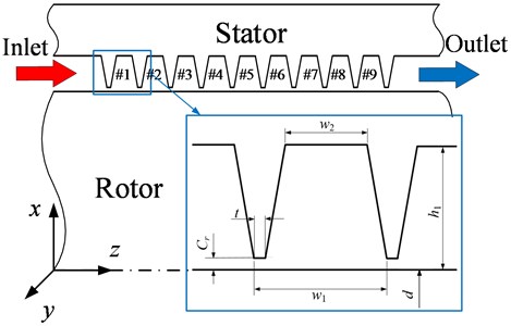
Table 1Seal dimensions
Parameter | Value |
Rotor diameter /mm | 60 |
Radial clearance / mm | 0.2 |
Cavity width / mm | 3.8 |
Cavity depth / mm | 3.5 |
Blade thickness / mm | 0.25 |
Blade space width / mm | 2.3 |
Number of blades | 5, 10, 15 |
3.2. Numerical model
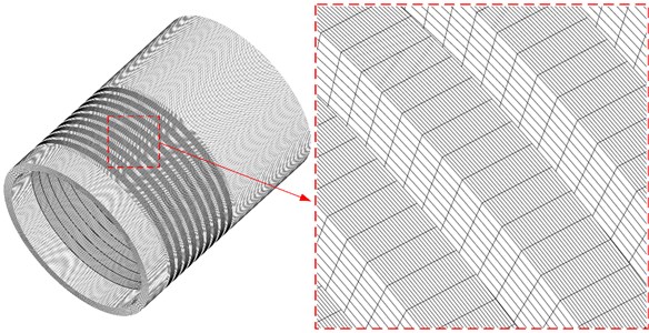
A commercial CFD software [28], which solves the compressible Reynolds-averaged Navier-Stokes equations, is employed in this paper. The standard - is used as the turbulence model with the turbulence intensity of 5 %. The scalable wall function method combines the physical quantity of the wall and the high-level turbulent zone. And the value of is controlled within 30-200. In order to investigate the effect of mesh densities for an accurate prediction of the rotordynamic coefficients, coarse and fine mesh grids were tested for the labyrinth seal. The fine mesh placed more nodes in radial and circumferential direction. For the labyrinth seal with 10 blades, the size of the coarse mesh and fine mesh are 2.4×10⁶ nodes and 5.6×10⁶ nodes, respectively. The difference of rotordynamic coefficients predicted by the coarse and fine mesh is under 1.68 %. Therefore, for the studied labyrinth seal in this paper, the mesh with nodes 2.4×10⁶ is accurate enough for the investigation. The grid distribution for the simulation(coarse) is shown in Fig. 4.
Fig. 4Grid distribution
3.3. Boundary conditions
Table 2 lists the detailed parameters for CFD calculation. The fluid (air) is assumed to be ideal gas. The inlet and outlet boundary were placed at the upstream of the inlet extension and the downstream of the outlet extension, respectively. The walls of rotor and stator are defined to be adiabatic, smooth and no slip. The total pressure and temperature are defined at the inlet boundary, while the average static pressure is specified at the outlet. The inlet preswirl ratio is defined as Eq. (6):
where, is the circumferential velocity at the seal inlet.
The desired convergent target of each numerical simulation is that the RMS residuals of the momentum and mass equations, energy equations, and turbulence equations are below 10-6.
Table 2Calculation conditions
Simulation condition | Value |
Fluid | Air (ideal gas) |
Turbulence model | Standard - |
Wall properties | Adiabatic, smooth surface |
Temperature /K | 287 |
Supply pressure / bar | 6.9 |
Discharge pressure / bar | 1 |
Inlet preswirl ratio | –0.3, –0.15, 0, 0.15, 0.3 |
Rotational speed /RPM | 15000 |
Whirling frequency /Hz | 0, 50, 100, 150 |
Whirling orbit | Circle orbit |
Whirling radius /mm | 0.01 |
3.4. Validation
In order to validate the reliability of the CFD simulation, this paper measured the static seal force acting on the rotor with various eccentric ratios, and compared the numerical results with experiments. Fig. 5 shows the experiment facility.
Fig. 5Gas facility, experiment part and testing system
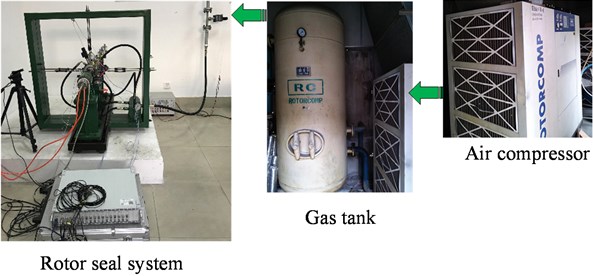
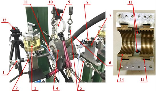
Fig. 6 shows detailed experiment device of the rotor-seal system. Two hydrodynamic bearings are used to support the rotor. The rotor diameter of the test section is 60 mm. The stator is supported by eight springs in vertical and horizontal directions. The labyrinth seal contains 10 blades, and the detailed dimension is shown in Fig. 3 and Table 1. Four inlet ports are arranged symmetrically around the middle plane of the cylindrical stator surface. High-pressure gas enters the seal from four centered inlet ports and discharges into the atmosphere. The inlet pressure is ~6.9 bar, and the rotational speed is zero. In the experiment, the zero calibration for all the test instruments is guaranteed to avoid the errors caused by their deviation.
Fig. 6Experimental device of the rotor-seal system: 1. Rotor, 2. #1 Journal bearing, 3. Turbine oil, 4. Stator, 5. Elastic support, 6. Inlet pipe, 7. #2 Journal bearing, 8. Displacement sensor, 9. Dial indicator, 10. Pressure sensors, 11. Balance disk, 12. Tachometric transducer, 13. Inlet port, 14. Blades, 15. Elastic metal insert
To improve the identification accuracy, the seal housing is supported by eight elastic springs in both horizontal and vertical directions. The dynamic response of the stator can be amplified by the supporting springs. By multiplying the stator displacement with the spring stiffness, the seal force acting on the rotor can be obtained. The stator displacement is measured by averaging 10 tests under the same working condition. Table 3 gives the comparison of the static experimental force and the results obtained by the CFD method. Because of the machining accuracy of the rotor and seal, a weak seal force can be found even the eccentric ratio is zero, which is small enough to be neglected. The difference between experiment and CFD simulation is less than 2.9 %, which verifies the accuracy of the current CFD simulation.
Table 3Comparison of the seal reaction force
Eccentric ratio | EXP / N | CFD / N | Error |
0 | 0.01 | 0 | 1.0 % |
0.05 | 0.42 | 0.41 | 2.4 % |
0.10 | 0.79 | 0.78 | 1.6 % |
0.15 | 1.12 | 1.16 | 2.9 % |
0.20 | 1.65 | 1.63 | 1.9 % |
4. Results and discussion
4.1. Static characteristics
The cross-coupled stiffness coefficient is one of the main criteria to evaluate the system stability. For a steady flow, the is the function of the tangential seal reaction force, as shown in Eq. (4). Fig. 7 shows the tangential seal reaction force vs. preswirl ratios for the labyrinth seal with different blade numbers. With the increasing preswirl ratio, the tangential seal reaction force of the labyrinth seal with 5 blades exhibits an opposite trend compared with that of the labyrinth seal with 15 blades. For the labyrinth seal with 5 blades, the tangential seal reaction force decreases with the increasing preswirl ratio, and corresponding cross-coupled stiffness coefficient becomes to be negative. From the stability viewpoint, the increasing preswirl ratio tends to enhance the stability. This result shows a contrary trend to the conventional conclusion. The tangential seal reaction force of the labyrinth seal with 15 blades increases with the rising preswirl ratio. The cross-coupled stiffness coefficient changes in signs from negative to positive, which processes the decreasing stability. One notable phenomenon for the labyrinth seal with 10 blades is that it shows little dependency on preswirl ratios and keeps an almost constant value. Above results show the tangential seal reaction force is greatly correlated with the blade number. The seal reaction force from each seal cavity is extracted to clarify the phenomenon in following section.
Figs. 8-10 show the tangential seal reaction forces inside each cavity for the labyrinth seal with 5, 10, 15 blades, respectively. For #1 cavity, the increasing preswirl decreases the tangential seal reaction force. However, the effect of preswirl on the seal reaction force inside #2~#14 cavity shows an opposite trend, and the increasing preswirl ratio tends to produce a larger seal reaction force.
Fig. 7Tangential seal reaction forces Ft vs. preswirl ratios
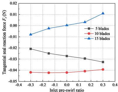
Fig. 8Tangential seal reaction forces Ft vs. seal cavities (5 blades)
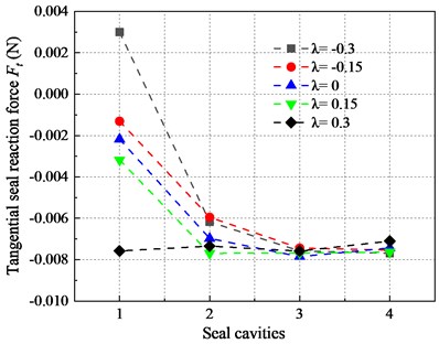
Fig. 9Tangential seal reaction forces Ft vs. seal cavities (10 blades)
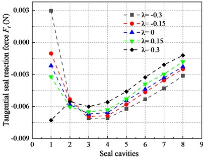
Fig. 10Tangential seal reaction forces Ft vs. seal cavities (15 blades)
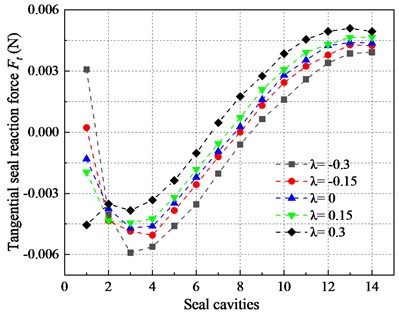
For the labyrinth seal with 5, 10, 15 blades, the preswirl mainly influences the fluid flow in #1 cavity, and it has a relatively minor effect on the flow in other seal cavities. Hence, when the number of seal cavities is relatively small (such as 5 blades in this paper), the changing trend of the tangential seal reaction force acting on the whole rotor largely depends on the force variation inside #1 cavity.
When the cavity number becomes relatively large (such as 15 blades in this paper), the tangential force inside #2~#14 cavities dominates the whole seal. The labyrinth seal with 10 blades shows little dependency on the preswirl ratio. This can be attributed to the counteracting effect of the flow forces between #1 cavity and other cavities.
Fig. 11 shows the distribution of high-pressure spots for the labyrinth seal with various blade numbers (0). is the circumferential angle of high pressure spots in spatial polar coordinate system. All high-pressure spots inside #1 cavity locate at the first quadrant (divergent gap), while in other cavities becomes more than 150°. Along the leakage direction, the high-pressure spot for each cavity continuously moves toward the rotational direction.
Fig. 11High pressure spots vs. seal cavities without inlet preswirl
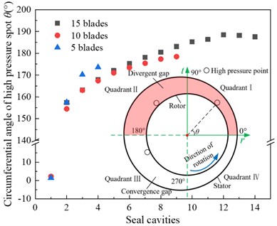
Fig. 12Effects of high pressure spots on the tangential seal reaction force
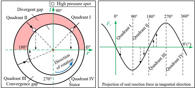
Fig. 12 depicts the direction and magnitude of the tangential seal reaction force due to the changing position of high-pressure spots affects. As the high-pressure spot locates in the first and second quadrants, the tangential seal reaction force shows a negative sign, which is consistent with the results for the labyrinth seal with 5 and 10 blades shown in Fig. 7. The shifting of high pressure spots inside cavities (except for the #1 cavity) from the second quadrant to the third quadrant results in a sign change of the tangential seal reaction force from negative to positive, which agrees with the variation of tangential seal reaction forces in Fig. 10. The main reason for the variation of the seal reaction force is that the circumferential location of the high-pressure spot for each seal cavity varies along the leakage direction.
Taking the labyrinth seal with 15 blades as an example, the variation of high-pressure spots for #1, #3, #7, #13 cavity is shown in Fig. 13. The pressure high spot shifts toward the inlet preswirl direction. Additionally, the inlet preswirl has a more dramatic effect on the seal cavity close to the inlet. Combining with Fig. 11, it’s obvious that the high-pressure spots of #1 cavity locate at the first and fourth quadrants. While the high-pressure spots of #2~14 cavities locate at the third and fourth quadrants.
Fig. 13Position of high-pressure spots vs. preswirl ratios
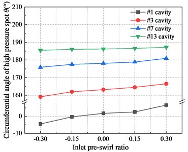
Fig. 14 presents the effect of various high-pressure spots on the tangential seal reaction force. Fig. 14(a) depicts the transition of the high-pressure spot in different quadrants. Fig. 14(b) shows the projection of the seal reaction force in the tangential direction ( axis). According to the distribution of high-pressure spots, the cavities, for which the high pressure spot locates at the first and fourth quadrant, are classified as Type A Cavity (e.g. # 1 cavity). And the other cavities, for which the high-pressure spot locates at the second and third quadrant, are classified as Type B Cavity (e.g. #2-#14 cavities). When the preswirl ratio is positive ( 0), the tangential seal reaction force in the Type A cavities shifts to be negative, while that in the Type B cavities converts to be positive. When the inlet preswirl ratio is negative ( 0), the tangential seal reaction force inside both Type A and B cavities show the opposite result. This phenomenon is consistent with the variation trend of tangential seal reaction forces shown in Fig. 10.
Fig. 14Effects of high pressure spot shifts caused by preswirls on the tangential seal reaction force
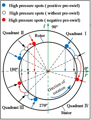
a) Hight pressure spot position
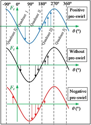
b) Projection of seal reaction force in axis
4.2. Dynamic characteristics
The effective damping coefficient is a main parameter to evaluate the system stability [32, 33], which is defined as follows:
where , , , , denote the tangential seal reaction force, radius of whirling orbit, direct damping coefficient, cross-coupled stiffness coefficient, respectively. The direct damping coefficient reveals the capacity for reducing the rotor whirling motion. The cross-coupled stiffness coefficient shows the destabilization effect. As a result, the effective damping coefficient could be employed to depict the resultant effect.
Fig. 15 presents the tangential seal reaction force inside seal cavities (15 blades) with whirling frequencies 0 Hz, 50 Hz, 100 Hz and 150 Hz. With the increasing whirling frequency, the seal reaction force in the tangential direction for each cavity becomes toward negative gradually. This is mainly because the increasing direct damping effect can suppress the whirling motion.
Fig. 15Distribution of the tangential seal reaction force inside seal cavities with different whirling frequencies (15 blades)
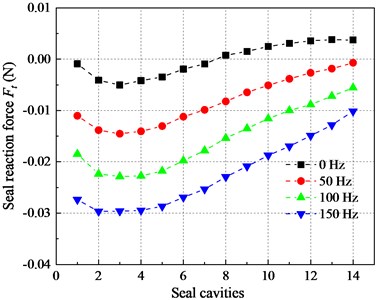
Fig. 16 shows the distribution of tangential seal reaction forces inside the cavities with a whirling frequency 50 Hz. It’s obvious that the responses of the seal reaction force inside the cavities working in dynamic conditions are similar with that working in the static condition.
Fig. 17 shows the effective damping coefficient versus inlet preswirl ratios with a whirling frequency 50 Hz. The labyrinth seal with different blade numbers differs greatly in the response to preswirl ratios. The increasing preswirl ratios enhances the stability of the labyrinth seal with 5 blades, while the labyrinth seal with 15 blades shows the opposite trend. The labyrinth seal with 10 blades shows the lowest preswirl dependency.
Fig. 16The tangential seal reaction force in seal cavities under different preswirl ratios (50 Hz)
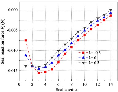
Fig. 17Effective damping coefficients for different blades numbers vs. preswirl ratios (50 Hz)
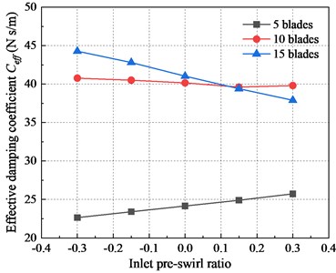
Under static and dynamic conditions, the stability of the labyrinth seal with 5 blades increases with the rising preswirl ratio, which is contrary to the traditional viewpoint. The main reason is that the circumferential position of the high pressure spot inside the #1 cavity is different from the others, which results in the different effect of the preswirl on the tangential force. When the blade number is small (e.g. 5 blades), the effect of preswirl on #1 cavity plays a dominant role, and the high pressure spot inside #1 cavity appears in the divergence gap. Meanwhile, the positive preswirl is conducive to improving the overall stability of the seal system. When the blade number is large, the effect of preswirl on #1 cavity is reduced by the other cavities, and the high pressure spot mainly appears in the convergence gap. The overall tangential seal reaction force is dominated by the downstream cavities, and the negative preswirl is beneficial to improve the system stability.
5. Conclusions
In this paper, the effect of inlet preswirls on the static and dynamic stability of the labyrinth seal with different blade numbers is studied based on experimental test and numerical simulation. Following conclusions are summarized.
The variation of the high-pressure spot for each seal cavity contributes to the change of tangential seal reaction forces in magnitude and direction. The inlet preswirl has a dramatic effect on the circumferential position of the high-pressure spot. For the labyrinth seal with different blade numbers, the difference of high-pressure spot position between #1 cavity and the others results in an opposite effect of the inlet preswirl ratio on the system stability.
For the labyrinth seal with fewer blades (e.g. 5 blades in this paper), a positive inlet preswirl could improve the system stability. For the labyrinth seal with 10 blades, it shows little dependency on preswirl ratios. For the labyrinth seal with more blades (e.g. 15 blades in this paper), a negative inlet preswirl will increase the system stability.
References
-
Childs D. W. Turbomachinery Rotordynamics: Phenomena, Modeling, and Analysis. John Wiley & Sons, 1993.
-
Childs D. W., Vance J. M. Annular gas seals and rotordynamics of compressors and turbines. Proceedings of the 26th Turbomachinery Symposium, Texas A&M University, College station, 1997.
-
Den Hartog J. P. Mechanical Vibrations. McGraw-Hill Book Co, New York, 1956.
-
Thomas H. J. Unstable oscillations of turbine rotors due to steam leakage in the clearance of the sealing glands and the blading. Bulletin Scientifique, Vol. 71, 1958, p. 1039-1063.
-
Alford J. S. Protecting turbomachinery from self-excited rotor whirl. Journal of Engineering for Power, Vol. 87, Issue 4, 1965, p. 333-343.
-
Rosenberg C. S., Orlik W. G., Marshenko U. A. Investigating aerodynamics transverse force in labyrinth seals in cases involving rotor eccentricity. C.E.Tran. 083, Translated from Energnmashinostrojohic, Vol. 8, Issue 27, 1974, p. 15-17.
-
Iwatsubo T., Matooka N., Kawai R. Flow induced force and flow patterns of labyrinth seals. NASA CP-2250 Proceedings of a Workshop at Texas A&M University, Rotordynamic Instability Problems in High Performance Turbomachinery, 1982.
-
Kostyuk A. G. A theoretical analysis of the aerodynamic forces in the labyrinth glands of turbomachines. Teploenergetica, Vol. 419, Issue 11, 1972, p. 29-33.
-
Kurohashi M., Inoue Y., Abe T., Fujikawa T. Spring and damping coefficients of the labyrinth seals. Proceedings IMechE – 2nd International Conference on Vibration in Rotating Machinery, Cambridge, England, 1980.
-
Childs D. W. Dynamic analysis of turbulent annular seals based on Hirs lubrication equation. Journal of Lubrication Technology, Vol. 105, 1983, p. 429-436.
-
Childs D. W., Scharrer J. K. An Iwatsubo-based solution for labyrinth seals: comparison to experimental results. Journal of Engineering for Gas Turbines and Power, Vol. 108, Issue 2, 1986, p. 325-331.
-
Benckert H., Wachter J. Flow induced spring coefficients of labyrinth seals for application in rotor dynamics. NASA Conference Publication 2133: Rotordynamic Instability Problems in High-Performance Turbomachinery, Texas A&M University, College Station, 1980.
-
Leong Y. M. M. S., Brown R. D. Circumferential Pressure Distributions in a Model Labyrinth Seal. NASA CP-2133, 1982, p. 222-232.
-
Thieleke G., Stetter H. Experimental Investigations of Exciting Forces Caused by Flow in Labyrinth Seals. NASA, Lewis Research Center, Rotordynamic Instability Problems in High-Performance Turbomachinery, 1991, p. 109-134.
-
Untaroiu A., Jin H., Fu G., Hayrapetiau V., Elebiary K. The effects of fluid preswirl and swirl brakes design on the performance of labyrinth seals. Journal of Engineering for Gas Turbines and Power, Vol. 140, Issue 8, 2018, p. 82503.
-
Tsukuda T., Hirano T., Watson C., Morgan N. R., Weaver B. K., Wood H. G. A numerical investigation of the effect of inlet preswirl ratio on rotordynamic characteristics of labyrinth seal. Journal of Engineering for Gas Turbines and Power, Vol. 140, Issue 8, 2018, p. 82506.
-
Kirk G. Labyrinth seal analysis for centrifugal compressor design – theory and practice. Proceedings of the 2nd IFToMM International Conference, Tokyo, Japan, 1986.
-
Memmott E. A. Tilt pad seal and damper bearing applications to high speed and high density centrifugal compressor. Proceedings of Third IFToMM International Conference, Lyon, France, 1990.
-
Memmott E. A. Stability of centrifugal compressor by application of tilt pad seals, damper bearings and shunt holes. Proceedings of 5th International Conference on Vibrations in Rotating Machinery ImechE, Bath, England, 1992.
-
Gelin A., Pugnet J., Bolusset D., Friez P. Experience in full load testing natural gas centrifugal compressors for rotordynamics improvements. ASME 1996 International Gas Turbine and Aeroengine Congress and Exhibition, 1996.
-
Soto E. A., Childs D. W. Experimental rotordynamic coefficient results for (a) a labyrinth seal with and without shunt injection and (b) a honeycomb seal. Journal of Engineering for Gas Turbines and Power, Vol. 121, Issue 1, 1999, p. 153-159.
-
Kim N., Park S. Y., Rhode D. L. Predicted effects of shunt injection on the rotordynamics of gas labyrinth seals. Journal of Engineering for Gas Turbines and Power, Vol. 125, Issue 1, 2003, p. 167-174.
-
Gans B. Reverse-swirl swirl brakes retrofitting with brush seals. Turbomachinery International, Vol. 48, 2007, p. 48-49.
-
Brown P. D., Childs D. W. Measurement versus predictions of rotordynamic coefficients of a hole-pattern gas seal with negative preswirl. Journal of Engineering for Gas Turbines and Power, Vol. 134, Issue 12, 2012, p. 122503.
-
Childs D. W., Mclean J. E., Zhang M., Arthur S. P. Rotordynamic performance of a negative-swirl brake for a tooth-on-stator labyrinth seal. Journal of Engineering for Gas Turbines and Power, Vol. 138, Issue 6, 2016, p. 62505.
-
Arghir M., Mariot A. About the negative direct static stiffness of highly eccentric straight annular seals. Journal of Engineering for Gas Turbines and Power, Vol. 137, Issue 8, 2015, p. 82508.
-
Childs D. W., Arthur S. P. Static destabilizing behavior for gas annular seals at high eccentricity ratios. ASME Turbo Expo 2013: Turbine Technical Conference and Exposition, San Antonio, USA. 2013.
-
Ansys CFX-Solver Theory Guide. Ansys, release 11.0, Canonsburg, Pennsylvania, 2006.
-
Muszynska A. Whirl and whip – rotor/bearing stability problems. Journal of Sound and Vibration, Vol. 110, Issue 3, 1986, p. 443-462.
-
Childs D. W., Nelson C. E., Nicks C., Scharrer J., Elrod D., Hale K. Theory versus experiment for the rotordynamic coefficients of annular gas seals: part 1 – test facility and apparatus. Journal of Tribology, Vol. 108, Issue 3, 1986, p. 426-431.
-
Hirano T., Guo Z. L., Kirk R. G. Application of computational fluid dynamics analysis for rotating machinery – part Ⅱ: labyrinth seal analysis. Journal of Engineering for Gas Turbines and Power, Vol. 127, Issue 4, 2005, p. 820-826.
-
Picardo A., Childs D. W. Rotordynamic coefficients for a tooth-on-stator labyrinth seal at 70 bar supply pressures: measurements versus theory and comparisons to a hole-pattern stator seal. Journal of Engineering for Gas Turbines and Power, Vol. 127, Issue 4, 2005, p. 843-855.
-
Ertas B. H., Delgado A., Vannini G. Rotordynamic force coefficients for three types of annular gas seals with inlet preswirl and high differential pressure ratio. Journal of Engineering for Gas Turbines and Power, Vol. 134, Issue 4, 2012, p. 42501.
Cited by
About this article
The authors are grateful for the Grants from the National Natural Science Foundation of China (51875361).
