Abstract
In this paper, a self-tunable energy harvester based on pendulum oscillations with a mechanical motion rectifier (MMR) system, which can convert vibration into electrical energy, is proposed. The harvester is composed of a pendulum excited by a slider-crank mechanism. The pendulum system is designed to automatically adjust its own natural frequency to match that of the imposed base excitation. Frequency adjustment in a proposed pendulum-type energy harvester is achieved by varying the length of the pendulum rod through changing the position of pendulum mass which mounted at its tip. The pendulum mass is driven by a ball screw through a stepper motor which controls the length of the pendulum automatically in accordance with the frequency of the external motion. The base motion frequency is detected by an infrared sensor. An ultrasonic distance sensor is used to detect the length of the pendulum rod and feeds this information to a microcontroller to obtain the corresponding natural frequency from a lookup table. The microcontroller calculates the frequency difference between natural frequency and excitation frequency and converts this value into a length difference through another lookup table. The microcontroller then gives instructions to drive a stepper motor through a sequence of steps to achieve the target length and keeps the device in resonance state to harvest maximum power during operation. Different time detection intervals were studied to investigate their effect on the tuning process. This study showed that the longer time intervals increase the detection accuracy for the calculation of low excitation frequency. The amount of energy consumed during the tuning process to adjust the pendulum length is presented. In this context, the consumed energy is only needed until the resonance of the device matches the excitation frequency. The harvester system was studied numerically and experimentally. Based on the findings of this work, the natural frequency of the harvester is successfully tuned below 0.7 Hz, when the length of pendulum rod is changed from 550 mm to 900 mm, generating power from 1.78 W to 4.1 W at an optimal load resistance value of 10 Ω and 3 Ω respectively at maximum excitation amplitude of 120 mm. Therefore, the proposed pendulum system can be used as an efficient harvester for producing power in low-frequency applications (< 1 Hz).
Highlights
- We present a self-tunable energy harvesting based on pendulum oscillation low-frequency vibration energy from horizontal excitations.
- The device is equipped with mechanical motion rectifier to translates bi-directional rotational motion into unidirectional rotational motion to improve the amount of power that can be harvested.
- The frequency adjustment of the system has been demonstrated experimentally by changing the length of the pendulum rod automatically through a complete control circuit to achieve a state of resonance.
1. Introduction
Energy harvesting is a process in which energy is collected from ambient sources, such as the dynamic motion of structures [1], sea waves [2], human motion [3, 4], and converting it to useful power which can be stored for powering electronic devices. There are many ways to convert the energy from ambient vibrations into electricity such as electrostatic [5], piezoelectric [6-8], and electromagnetic harvesters [9, 10]. If the harvester is designed to have a fixed resonance frequency, this will limit the bandwidth of the device [11]. In many applications, the ambient frequency fluctuates due to fabrication inconsistencies, which leads to a reduction in energy generation [12]. There are different techniques to address this problem, such as widening the bandwidth of the harvester and tuning the resonance frequency of a single generator periodically so that it matches the frequency of the ambient vibration. Bandwidth can be widened by designing the harvester to adjust its natural frequencies [13, 14] and with devices having multiple oscillators [15-17]. Moreover, several studies [18-24] have considered nonlinear behavior to increase the power generation over a wider frequency range.
Other research has focused on tuning the system’s natural frequency [25]. The resonance frequency of a cantilever structure can be tuned by applying an axial force by adjusting the distance between two permanent magnets [26, 27]. Another approach is to change the location of the proof mass mounted on the cantilever [14, 28]. Autonomous frequency tuning refers to the ability of the harvester to self-adjust its properties according to the given environmental conditions [29]. In this context, Refs. [30, 31] achieved the resonance frequency matching by straining the structure automatically. Natural frequencies can also be adjusted automatically through changing the rotary inertia of a cantilever-type energy harvester [32]. Other work [33] employed nonlinear magnetic forces to achieve a wide range of frequency tunability of the harvester. A nonlinear inertia coupling property of the X-structure harvester is used to tune the ultralow-frequency range by changing the structure parameters [34]. Other research on adjusting the frequency through changing the dimensions of the structure include [35, 36].
A review of the aforementioned research reveals that cantilever devices have been predominantly used in energy harvesting applications. These devices are known to possess natural frequencies that are higher than those encountered in large structures, such as buildings and bridges, which typically have resonances within 1 to 3 Hz. This has prompted research into the use of mechanical pendulums for energy harvesting, which can be designed to offer low natural frequencies with higher energy density [21, 22, 37, 38]. While pendulums have been proposed for energy harvesting, the design of self-tunable pendulum devices has been granted less attention.
This paper aims to develop a novel energy harvester based on pendulum oscillations to harvest low-frequency vibration energy from horizontal excitations. The proposed design is capable of altering the harvester resonance frequency by changing the length of the pendulum automatically to match the excitation frequency. The device is equipped with a mechanical motion rectifier (MMR) to convert the bidirectional movement of the pendulum into a unidirectional rotary motion. MMRs have been previously used [39-42] to improve the performance of energy harvesters.
The proposed energy harvester is relatively large and heavy, and it can be driven at frequencies less than 1 Hz, making it an ideal candidate for operation in structural applications, which have low frequency [< 1 Hz] such as bridges [43, 44]. The proposed energy harvester is designed to self-adjust its natural frequency according to the operating conditions. Frequency adjustment is attained through changing the pendulum length to tune the device to operate across a variable frequency range. An infrared sensor is used to find out the frequency of pendulum oscillation and an ultrasonic distance sensor is used to identify the position of the pendulum mass. A microcontroller is used to drive a stepper motor to maintain the system in a resonance state.
The remainder of this article is organized into three sections. Section 2 outlines the design and modeling of the electromechanical system to simulate the dynamics of a base excited pendulum and to predict the output voltage as a function of the design parameters. Section 3 presents an experimental validation of the harvested power, the proposed tuning algorithm, and the energy consumed by actuator during tuning operation, whereas Section 4 is dedicated to conclusions.
2. Design and modeling
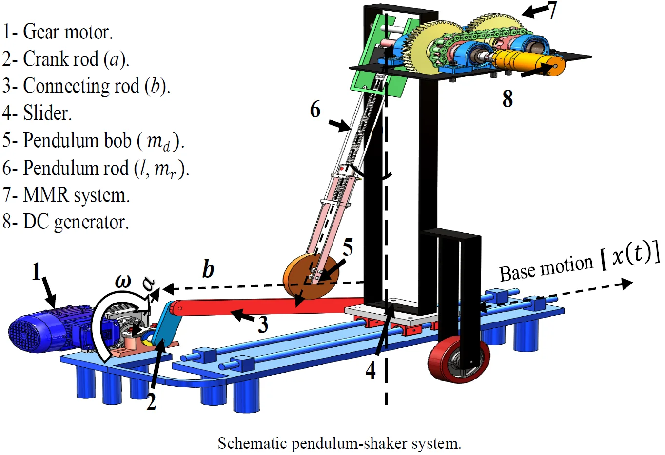
Fig. 1 shows a schematic illustration of the proposed energy harvester system. The concept depends on harvesting energy from pendulum oscillations. The pendulum consists of a bob of mass and a rod of length has a mass . The pendulum rod is composed of a ball screw connected to the stepper motor to allow the variation of pendulum length and change the bob position by a control unit. Through this way, the natural frequency of the pendulum system can be adjusted according to the excitation frequency. The angle is positively measured anticlockwise from the hanging position . The gear-motor is used to drive the crank-rod system into low-frequency reciprocating motion to the slider.
A reciprocating motion provided by a crank-rod system [45] constitutes the imposed base excited motion to the pendulum device. A crankshaft rotates at a constant frequency , following a circumferential trajectory. Such excitation gives to the pendulum system the following displacement [45]:
where is the crank rod length, is the connecting rod length. If the length of the crank is small in comparison to the length of the connecting rod, the motion becomes close to sinusoidal [46].
The DC generator coupled to the pendulum axis to extract electricity from pendulum oscillations. The MMR system is used to drive the generator shaft in the unidirectional rotational motion through two one-way bearings.
Fig. 1Schematic pendulum-shaker system
The governing differential equation of the proposed design can be set up by using Lagrange’s equation [47].
The kinetic energy of the system is given as:
The potential energy of the system is given as:
Lagrangian of the system is written as:
The second-order ordinary differential equation given by:
where is the viscous friction force. The viscous damping force in pendulum joint opposing the swing of the pendulum can be expressed as [37, 48]:
where is a damping coefficient of the pendulum joint. Now, entering the second derivative of Eq. (1) and Eq. (7) into Eq. (6), the proposed form of the equation governing the pendulum model:
2.1. Mechanical–electrical coupling model
The electromotive force (EMF) generated by the DC generator is proportional to the input speed on the generator shaft [49] thus:
where is the constant for the internal loss coefficient in the motor, is the gear ratio, is an angular velocity of a pendulum.
The proposed form of the governing equation which combining mechanical and electrical damping is given by Eq. (10):
The voltage/current relationship is given by [50]:
where – current, – armature resistance, – armature inductance, – load resistance.
The harvested power is given by [51]:
2.2. Numerical investigation
In this section, the key parameters including the change of the pendulum length and hence its natural frequency are studied to analyze their effects on the dynamic response of the energy harvester and the power output by solving Eq. (10) using numerical analysis based on a state-space representation. The power output will be discussed in detail in Sec 3.1. Values of parameters chosen for this simulation are 7 kg, 3 kg, 120 mm, and 700 mm. A series of free vibrations tests were undertaken to evaluate the viscous damping coefficient required in this simulation. The relation of the logarithmic decrement () is used to calculate the damping ratio () and get the corresponding values of viscous damping coefficient () based on the variation of the pendulum length. The range of the viscous damping coefficients is (0.5-0.8) Nms /rad according to the variation of the pendulum length in the range (550-900) mm respectively. As a sample Fig. 2(a) demonstrates the beating response of the pendulum angular displacement at pendulum length is 750 mm when the pendulum is excited with a frequency close to its natural frequency and with constant amplitude for 120 mm, whereas Fig. 2(b) shows the resonance response of the pendulum angular displacement at pendulum length 600 mm and 120 mm amplitude of excitation.
Fig. 2Time history plots of the pendulum angular displacement
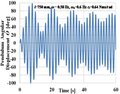
a) Beating phenomena
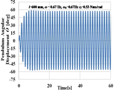
b) Resonance response
3. Experimental setup
The purpose of this section is to document the experimental work carried out to validate the mechanical and electrical model presented in Section 2. Moreover, the automatic tuning technique to modify the tuning pendulum length according to the changing excitation frequencies through a complete control circuit is discussed. The energy consumed by the actuator and the time to recover the expended energy in performing the tuning are also discussed.
As shown in Fig. 3, the whole pendulum set is mounted on crank-slider mechanism and the rotary motion of the crankshaft is produced by an electrical gear- motor of 0.75 HP. The velocity of gear- motor controlled by inverter IC5 (svo15ic5) [52]. Table 1 shows the dimensions and material properties used in experimental study.
Table 1Physical properties and dimensions of the energy harvester
Parameter | Value |
(550-900) mm | |
(50,70, and 120) mm | |
700 mm | |
7 kg | |
3 kg | |
210 GPa | |
7800 kg/m3 |
The amplitude of excitation can be changed manually by a set of screws [50, 70, and 120] mm. The pendulum rod is attached to the stepper motor shaft to allow the testing of different lengths of the tuning pendulum arm. The practical limits of a pendulum length are 550 mm to 900 mm, thus natural frequency can be varied from 0.47 to 0.68 Hz.
Fig. 3Experimental setup
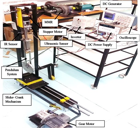
The tuning pendulum arm is attached to a shaft, which is in turn mounted on two ball bearings (bearing diameter, 12 mm) to the supporting frame. A four-phase stepper motor (NEMA 23) with a maximum torque 3 N.m is attached at the pendulum’s tip and enables automatic adjustment of the pendulum length.
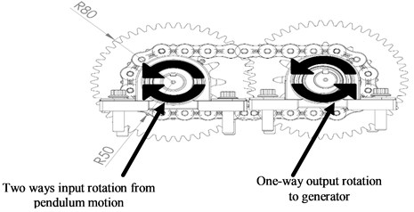
Fig. 4Working principle of MMR
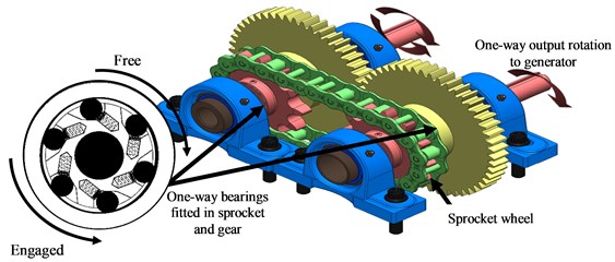
a) 3D MMR drawing
b) 2D theory concept for MMR system
The rotary motion of the pendulum is collected and then transmitted to a mechanical motion rectifier. The MMR is a device that translates bi-directional rotational motion into unidirectional rotational motion to improve the amount of power that can be harvested from the pendulum rotation. As shown in Fig. 4, the proposed MMR contains a pair of spaced-shafts having two rotary elements sprocket wheel and gear. The sprocket and the gear are engaged with two one –way bearings which allowing each shaft to rotate in one direction and slip on the other direction producing a generator shaft to rotate in one direction only.
3.1. Harvested power
An external resistance load in the range from 1 Ω to 2 kΩ is connected to analyze these effects on the output power. The load resistance should be selected to maximize the harvested power. The amount of electrical energy harvested was measured with a digital storage oscilloscope (Model TBS1064, Tektronix). These electrical loads are connected to DC generator, (80805 0X024.5Z) [53], to compare harvester performance in different working conditions. Electrical parameters of generator used for the experimental study and the simulations are given in Table 2. As an example of the result for DC voltage with the pendulum length of 750 mm, excitation frequency of 0.58 Hz and resistance load 110 Ω is shown in Fig. 5.
Table 2Electrical parameters of DC generator
Generator current | 1.45 A | |
Generator volt | 12 V | |
Electromotive force constant | 0. 43 Vs/rad | |
Coil inductance | 0.023 H | |
Coil resistance | 3.5 Ω | |
Inertia of motor | 0.083 kg m2 | |
Damping constant | 0.006 Nms/rad | |
Speed | 106 rpm | |
Gear ratio | 1:24 |
Fig. 5Experimental result of DC voltage
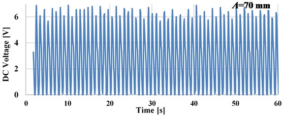
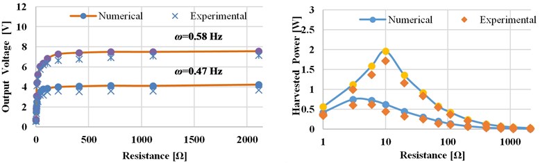
The result shows, the backlash in the gear system of MMR leads to a slight reduction in the output voltage. In this section, the performance of pendulum- energy harvester is studied and the optimum working conditions are determined to optimize the electrical power output. The key parameters including, pendulum length, excitation amplitude, and electrical load resistance are studied individually to analyze the effects on the performance of the energy harvester and the power output. As a sample Fig. 6 shows the experimental and numerical result of the output voltage and power as a function of resistance load of the pendulum length 750 mm for excitation frequencies are 0.47 and 0.58 Hz at 70 mm excitation amplitude. As shown in Fig. 6, the peak power value occurred when the pendulum system is excited near to the resonance frequency (0.58 Hz) across a resistor of 10 Ω. As shown in Fig. 6, the numerical predictions are shown to compare favorably with the experimental results.
Table 3 shows how the amplitude of base excitation affects the peak value of the harvested power at various pendulum length when the pendulum system is excited at the resonance state. The results obtained that the harvested power increases with the increase in excitation amplitude and observe that there is a linear relationship between the output voltage and the excitation vibration amplitude [54].
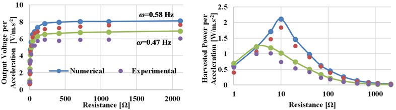
Fig. 6Numerical and experimental output voltage and power versus load resistance (at excitation amplitude A= 70 mm, pendulum length l= 750 mm)
a) Output voltage and power
b) Output voltage and power per acceleration
Table 3The variation of the experimental peak value of the harvested power according to excitation amplitude
Amplitude of base excitation [mm] | Pendulum length [mm] | Input excitation frequency [Hz] | Peak output power [W] | Optimal resistance [Ω] |
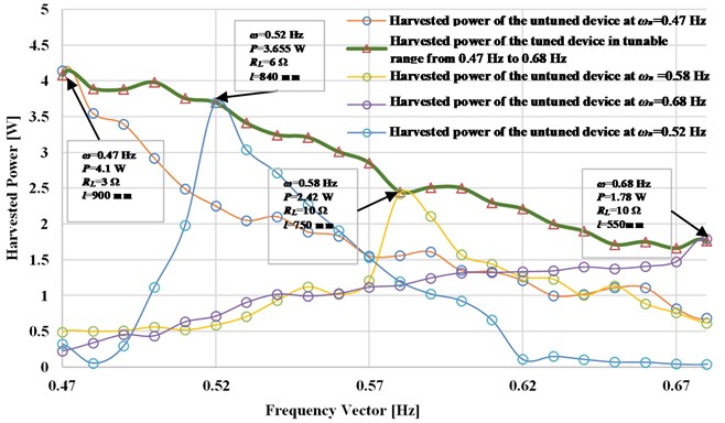
70 | 550 750 900 | 0.68 0.58 0.47 | 0.88 1.71 2.4 | 10 10 6 |
120 | 550 750 900 | 0.68 0.58 0.47 | 1.78 2.42 4.1 | 10 6 3 |
3.2. Frequency tuning
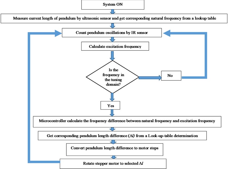
After getting a relation between tuning pendulum length () and the resonance frequency of the pendulum system, the tuning pendulum length is adjusted concerning to the base excitation frequency to keep the device in resonance state and harvest maximum power during operation, as illustrated in a flowchart in Fig. 7.
The tuning procedure in Fig. 7 starts by positioning the tuning pendulum arm to its zero degrees when the tuning system is switched ON. First, the control algorithm detects the pendulum mass position using the HC-SR04 ultrasonic distance sensor which attached in a fixed plate (as shown in Fig. 3) to transmit ultrasonic waves into the air and detects the reflected wave from the movable plate, which attached to the pendulum mass, and then get the corresponding natural frequency.
Thereafter, the IR sensor starts to detect the excitation frequency by sensing the pendulum oscillations and the microcontroller used to count the pulses during the interval time to calculate the vibration frequency. If the detected frequency is out of the domain, the system ignores the reading to avoid error pulsations in the frequency reading and keep the system response smoother. If the frequency is in tunable range, the microcontroller calculates the frequency difference and then gets the corresponding pendulum length difference from a lookup table determination. After that, the microcontroller calculates the necessary number of motor steps to achieve the target length and keep the harvester system in the resonance state. A stepper motor driver (TB6600) is used to take pulse signals from the microcontroller and converts them to motor motion.
Fig. 7Algorithm for the frequency tuning
3.2.1. Frequency detection
In this section, we will show the detailed analysis for calculating the excitation frequency. The infrared sensor is used to send a voltage pulse to the microcontroller every time its infrared ray is obstructed. The microcontroller counts the pulses during the detection interval to calculate the excitation frequency. As the pendulum rod oscillates in a sinusoidal pattern, each pair of pulses indicates a signal oscillation of the pendulum, which leads the detected frequency to be calculated as:
where is the number of pulses measured during the detection interval . When the time interval for calculating excitation frequency is changed, the resolution of the controller will also change. The resolution of the controller is the smallest segment size that the microcontroller can recognize, which can be defined in the proposed harvester as:
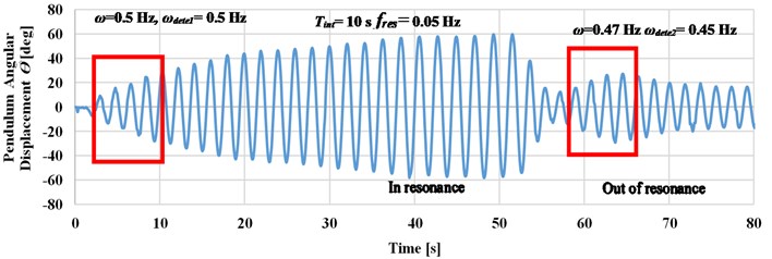
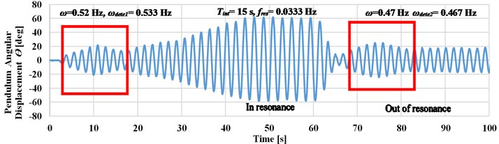
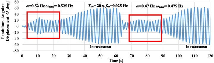
where is the frequency resolution, the dynamic response of the pendulum’s angular displacement at four different detection intervals is now studied. Fig. 8 shows four experimental cases where the system was excited at a frequency which is altered between 0.47 and 0.68 Hz. The pendulum angular displacements response is recorded for a different time interval detection of 5, 10, 15, and 20 seconds to calculate their experimental frequency measurements .
The frequency resolution corresponding to these intervals (according to Eq. (14)) are 0.025, 0.0333, 0.05, and 0.1 [Hz]. In the first of the experiment, the tuning pendulum rod was placed at its equilibrium position and the ultrasonic distance sensor is measured the position of pendulum mass and its natural frequency. If the detected frequency was subject to a tunable frequency range, the system will adjust pendulum length automatically to tune with .
Fig. 8Effect of time interval detection on the harvester response at maximum amplitude is 120 mm
a) Pendulum angular displacement response at 5 seconds
b) Pendulum angular displacement response at 10 seconds
c) Pendulum angular displacement response at 15 seconds
d) Pendulum angular displacement response at 20 seconds
As shown in Fig. 8, the longer time detection intervals leads to an accurate detection of the input frequency. This enables to decrease the value of deviation between the input frequency and the detected frequency, as in case when the excitation frequency is changed manually to 0.47 Hz as compared to cases , , and .
If the system is excited up to 0.47 Hz (at 0.5 Hz), as in case b, the deviation value reaches to zero which leads to accurate detection of the input frequency. Small deviation value has occurred as compared case d to case c when the system is excited at 0.52 Hz. Through the previous study, the detection time interval is selected to be 20 seconds to increase the detection accuracy at frequencies less than 0.5 Hz.
3.2.2. Frequency tuning control scheme
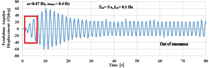
Fig. 9 illustrates the autonomous operation of the system and its capability of self-adjusting its natural frequency to match that of the incoming vibration to produce more power. The DC voltage and the pendulum angular displacement waveforms are measured by connecting one channel of the DC generator and connecting another channel with a rotary potentiometer 20 kΩ [55].
Fig. 9Time history plots for tuning operation
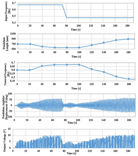
For the scenario shown, the base excitation action starts at 0 by the slider-crank mechanism. At the beginning, the energy harvester is switched ON with its pendulum rod is initially positioned at 700 mm and at excitation amplitude of 120 mm. As shown in Fig. 9, the energy harvester is first excited at 0.68 Hz, the IR sensor takes 20 s to count pendulum oscillations and calculate output frequency by the microcontroller. At the same moment, the ultrasonic distance sensor measures the current length of the pendulum and gets the corresponding natural frequency from a lookup table. After the detection interval of 20 s, the microcontroller drives the stepper motor to adjust the length automatically through a sequence of steps. After 55 s, the pendulum system is in resonance state, which leads to an increase in the output voltage. Then, the excitation frequency is changed manually to 0.47 Hz using the inverter. As a result, the output voltage decays as the system is out of resonance. After that, the IR sensor counts the new pendulum oscillations and the new output frequency is calculated. The ultrasonic distance sensor measures the new current length, and then the stepper motor takes the command from the microcontroller to adjust pendulum length automatically to match the harvester’s natural frequency with that of the incoming vibrations.
3.3. Power output versus frequency
Fig. 10 shows the output power versus frequency as obtained experimentally for three cases where the pendulum length is not adjusted (hence the harvester is tuned to a single frequency), as compared to the case where the device adjusts its length continuously to achieve resonance. When the pendulum length is not altered, the device produces maximum power at resonance, which occurs frequencies of 0.47, 0.58, and 0.68 Hz corresponding to pendulum lengths of 900, 750, and 550 mm, respectively. The output power drops significantly away from these frequencies. For the variable-length pendulum, maximum power is attained across a broader frequency band (with optimal resistive loading at each frequency) and ranges from 1.78 W to 4.1 W for an excitation amplitude of 120 mm. The power –frequency curves (illustrated with circles) for the untuned device to various resonance frequencies are shown. The thick green line (illustrated with triangles) indicates the maximum power output of the device if it were to be tuned to resonance.
Fig. 10The experimental harvested power versus resonant frequencies of the pendulum system at an excitation amplitude 120 mm
3.4. Energy consumed by the actuator
The energy required by the actuator to adjust the pendulum length is estimated experimentally as shown in Fig. 11. The energy used to drive the actuator is depend on the distance through which the pendulum mass has to be displaced to the desired position. The velocity of the actuator to drive the pendulum bob mass when subjected to a 2.5 A and 3.2 V, input to actuator, is determine to be 5 mm/s through several experiments. The time required to displace the pendulum mass to the desired location is given as:
where and are the final and initial positions of the pendulum mass and is the velocity of the actuator. Upon evaluating the time required, the total electrical energy consumed by the actuator can be given as:
where is the input voltage to the motor and is the electrical current in the motor.
Fig. 11Energy consumed by the actuator and the time taken for the device to recover the energy
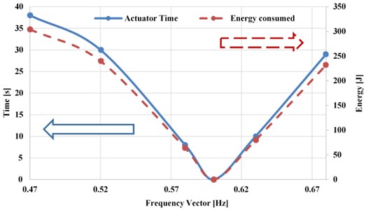
The amount of electrical energy consumed was found to be 232 J-304 J when tuned from the initial untuned resonance frequency (0.6 Hz which corresponding to pendulum length 700 mm) to 0.68 Hz and 0.47 Hz, respectively.
4. Conclusions
In this work, a self –tunable pendulum shaker energy harvesting system, capable of adjusting its resonance frequency to the excitation frequency, was modeled, developed and tested. The frequency adjustment of the system has been demonstrated experimentally by changing the length of the pendulum rod automatically through a complete control circuit to achieve a state of resonance. Additionally, the effect of time detection intervals on the accuracy of tuning operation is studied experimentally. The resonance frequency was successfully tuned in the range below 0.7 Hz by varying the pendulum length from 550 mm to 900 mm automatically with a response time of 20 seconds. The total energy consumed by the actuator is evaluated experimentally based on the distance traveled to adjust the pendulum length for resonance frequency tuning. The system was studied numerically and experimentally and was able to follow the applied frequency if it was changed arbitrarily. Experimental measurements showed that a device can generate the maximum output power of 4.1 W which corresponding to 3 Ω when the pendulum length reaches to 900 mm at a tuned resonance frequency of 0.47 Hz and excitation amplitude 120 mm. The benefit of using the control unit is to expand the bandwidth from (0.47-0.68) Hz.
References
-
Kouichi T., Eiichi S., Yusuke K. Design and parametric study on energy harvesting from bridge vibration using tuned dual-mass damper systems. Journal of Sound and Vibration, Vol. 361, 2016, p. 50-65.
-
Carlos V., Daniel T., Antoni M., Joaquin R. Sea motion electrical energy generator for low power applications. IEEE Conference Proceeding Standard on Piezoelectricity, 2013.
-
Carroll D., Duffy M. Demonstration of wearable power generator. Proceedings of the 11th European Conference on Power Electronics and Applications. Dresden, Germany, 2005.
-
Geisler M., Boisseau S., Perez M., Gasnier P., Willemin J., Ait Ali, Perraud S. Human-motion energy harvester for autonomous body area sensors. Smart Material and Structure, Vol. 26, Issue 3, 2017, p. 035028.
-
Mitcheson P. D., et al. MEMS electrostatic micro power generator for low frequency operation. Sensors and Actuators A: Physical, Vol. 115, Issue 2, 2004, p. 523-529.
-
Dutoit N. E., Wardle B. L. Experimental verification of models for microfabricated piezoelectric vibration energy harvesters. AIAA Journal, Vol. 45, Issue 5, 2007, https://doi.org/10.2514/1.25047.
-
Roundy S., Wright P. K., Rabaey J. A study of low level vibrations as a power source for wireless sensor nodes. Computer Communications, Vol. 26, Issue 11, 2003, p. 1131-1144.
-
Glynne J. P., Beeby S., White N. Towards a piezoelectric vibration-powered microgenerator. IEE Proceedings- Science, Measurement and Technology, Vol. 148, Issue 2, 2001, p. 68-72.
-
Williams C. B., et al. Development of an electromagnetic micro-generator. IEE Proceedings-Circuits Devices and Systems, Vol. 148, Issue 6, 2001, p. 337-342.
-
Glynne Jones P., et al. An electromagnetic, vibration-powered generator for intelligent sensor systems. Sensors and Actuators A: Physical, Vol. 110, Issue 1, 2004, p. 344-349.
-
Toyabur R. M., Salauddin M., Park J. Y. Design and experiment of piezoelectric multimodal energy harvester for low frequency vibration. Ceramics International, Vol. 43, Issue 1, 2017, p. 5675-5681.
-
Williams C. B., Yates R. B. Analysis of a micro-electric generator for microsystems. Sensors and Actuators A: Physical, Vol. 52, 1996, p. 8-11.
-
Youngsman J. M., Luedeman T., Morris D. J., Anderson M. J., Bahr D. F. A model for an extensional mode resonator used as a frequency-adjustable vibration energy harvester. Journal of Sound and Vibration, Vol. 329, Issue 3, 2010, p. 277-288.
-
Wang Y. J., Chen C. D., Sung C. K. Design of a frequency-adjusting device for harvesting energy from a rotating wheel. Sensors and Actuators A: Physical, Vol. 159, Issue 2, 2010, p. 196-203.
-
Shaofan Q., Shuttleworth R., Qlutunde O. S., Wright J. Design of a multiresonant beam for broadband piezoelectric energy harvesting. Smart Material and Structure, Vol. 19, Issue 9, 2010, p. 094009.
-
Ferraria M., Alghisi D., Baù M., Ferrari V. Nonlinear multi-frequency converter array for vibration energy harvesting in autonomous sensors. Procedia Engineering, Vol. 47, 2012, p. 410-413.
-
Malaji P. V., Ali S. F. Broadband energy harvesting with mechanically coupled harvesters. Sensors and Actuators A: Physical, Vol. 255, 2017, p. 1-9.
-
Arrieta A. F., Hagedorn P., Erturk A., Inman D. J. A piezoelectric bistable plate for nonlinear broadband energy harvesting. Applied Physics Letters, Vol. 97, Issue 10, 2010, p. 104102.
-
Malajia P. V., Ali S. F. Analysis of energy harvesting from multiple pendulums with and without mechanical coupling. The European Physical Journal Special Topics, Vol. 224, 2015, p. 2823-2838.
-
Junyi C., Shengxi Z., Daniel J. I., Jing L. Nonlinear dynamic characteristics of variable inclination magnetically coupled piezoelectric energy harvesters. Journal of Vibration and Acoustics, Vol. 137, Issue 2, 2015, p. 021015.
-
Dai X. A vibration energy harvester with broadband and frequency-doubling characteristics based on rotary pendulum. Sensors and Actuators A: Physical, Vol. 241, 2016, p. 161-168.
-
Jia Y. U., Yan J., Soga K., Ashwin A. S. A parametrically excited vibration energy harvester. Journal of Intelligent Material Systems and Structures, Vol. 25, Issue 3, 2013, p. 278-289.
-
Yan Z., Hajj M. R. Nonlinear performances of an autoparametric vibration-based piezoelastic energy harvester. Journal of Intelligent Material Systems and Structures, Vol. 28, Issue 2, 2017, p. 254-271.
-
Chongfeng W., Xingjian J. A comprehensive review on vibration energy harvesting modelling and realization. Renewable and Sustainable Energy Reviews, Vol. 74, 2017, p. 1-18.
-
Leland E. S., Wright P. K. Resonance tuning of piezoelectric vibration energy scavenging generators using compressive axial preload. Smart Material and Structure, Vol. 15, 2006, p. 1413.
-
Challa V. R., Prasad M. G., Shi Y., Fisher F. T. A vibration energy harvesting device with bidirectional resonance frequency tunability. Smart Material and Structure, Vol. 17, 2008, p. 015035.
-
Mohamed O. M., Mustafa H. A., Said M. M. Resonator with magnetically adjustable natural frequency for vibration energy harvesting. Sensors and Actuators A: Physical, Vol. 163, Issue 1, 2010, p. 297-303.
-
Xiaoming W., Jianhui L., Seiki K., Kia Z., Tianling R., Litian L. A frequency adjustable vibration energy harvester. Proceedings of Power MEMS, 2008, p. 245-248.
-
Sutrisno W. I., Wahied G. A. A review on frequency tuning methods for piezoelectric energy harvesting systems. Journal of Renewable and Sustainable Energy, Vol. 4, Issue 6, 2012, p. 062703.
-
Noha A. A., Mustafa H. A., Said M. M. A self-tuning resonator for vibration energy harvesting. Sensors and Actuators A: Physical, Vol. 201, 2013, p. 328-334.
-
Hoffmann D., Willmann A., Hehn T., Folkmer B., Manoli Y. A self-adaptive energy harvesting system. Smart Materials and Structures, Vol. 25, 2016, p. 035013.
-
Peter I., Omar N., Mustafa A., Yasser A. On adjusting the rotary inertia of a cantilever-type energy harvester for wideband operation. Procedia Engineering, Vol. 199, 2017, p. 3422-3427.
-
Sofiane B., Yongchen R., Arwed S., Chengdong Y., Siyang H., Fred L., Tamara B., Dennis H. System-level model and simulation of a frequency- tunable vibration energy harvester. Micromachines, Vol. 11, Issue 1, 2020, p. 91.
-
Meng L., Xingjian J. Novel tunable broadband piezoelectric harvesters for ultralow-frequency bridge vibration energy harvesting. Applied Energy, Vol. 255, 2019, p. 113829.
-
Jo S. E., Kim M. S., Kim Y. J. Passive-self-tunable vibrational energy harvester. 16th International Solid-State Sensors, Actuators and Microssystems Conference (Transducers), 2011, p. 691-694.
-
Jacek F. G., Jae H. O., Mihai H., Harshad S. S. Electromechanical Energy Harvesting System. US Patent 8,222,775 B2, 2012.
-
Michał M., Błażej W., Krzysztof J., Przemysław P., Tomasz Kapitaniaka Energy harvesting from pendulum oscillations. International Journal of Non-Linear Mechanics, Vol. 94, 2017, p. 251-256.
-
Yipeng W., Jinhao Q., Hongli J., Shengpeng Z. Piezoelectric spring pendulum oscillator for animal/human motion energy harvesting. Proceedings of the IEEE/ASME International Conference on Advanced Intelligent Mechatronics (AIM), Auckland, New Zealand, 2018.
-
Zhongjie L., Lei Z., George L., Linangjun L., Yixian Q. Electromagnetic energy-harvesting shock absorbers: design, modeling, and road tests. IEEE Transactions on Vehicular Technology, Vol. 62, Issue 3, 2013, p. 1065-1074.
-
Changwei L., You W., Lei Z. Broadband pendulum energy harvester. Smart Material and Structure, Vol. 25, 2016, p. 095042.
-
Yilun L., Lin X., Lei Z. Design, modeling, lab and field tests of a mechanical-motion-rectifier-based energy harvester using a ball-screw mechanism. IEEE/ASME Transactions on Mechatronics, 2017.
-
Changwei L., Junxiao A., Lei Z. Design, fabrication, simulation and testing of an ocean wave energy converter with mechanical motion rectifier. Ocean Engineering, Vol. 136, 2017, p. 190-200.
-
Farid U. K., Iftikhar A. Review of energy harvesters utilizing bridge vibrations. Shock and Vibration, Vol. 2016, 2016, p. 1340402.
-
Edward S., Member I., Haodong L., Darrell C., Pragasen P. Self-powered sensors for monitoring of highway bridges. IEEE Sensors Journal, Vol. 9, 2009, p. 1422-1429.
-
Jr Jhon J. D. Theory of Machines and Mechanisms. Third Edition, New York Oxford University, 2003.
-
Robert L. N. Design of Machinery. Fifth Edition, McGraw-Hill Education, 1991.
-
Thompson J., Stewart H. Nonlinear Dynamics and Chaos. Second Edition. Wiley, West Sussex, England, 2002.
-
Nelson R. A., Olsson M. G. The pendulum −rich dynamics from a simple system. American Journal of Physics, Vol. 54, Issue 2, 1986, p. 112-121.
-
Rafael H. A., Angelo M. T., Jose M. B., Airton N., Helio A. N. On nonlinear dynamics behavior of an electro-mechanical pendulum excited by a non-ideal motor and a chaos control taking into account parametric errors. Journal of the Brazilian Society of Mechanical Sciences and Engineering, Vol. 40, 2018, p. 23.
-
Chapman S. J. Electric Machinery Fundamentals. Fifth Edition, McGraw- Hill Education, New York, 2012.
-
Behnke C., Klassen A., Schomburg W. K. Energy harvesting employing a drive similar as a clock unit. Energy Harvesting and Systems, Vol. 4, Issue 3, 2017, p. 137-141.
-
User manual, SV-iC5. T-Solutions, https://inverterdrive.com/file/LS-Starvert-iC5-Manual.
-
D.C. Motors. Crouzet, http://stevenengineering.com/Tech_Support/PDFs/44MOTORS.pdf.
-
Bin Y., Chengkuo L., Wenfeng X., Jin X., Johnny H. H., Rama K. K., Siew P. L., Hanhua F. Electromagnetic energy harvesting from vibrations of multiple frequencies. Micromechanics and Micro Engineering, Vol. 19, 2009, p. 8.
-
Future Electronic, https://store.fut-electronics.com/collections/potentiometers.
About this article

