Abstract
In this paper, In order to make use of the rotating motion characteristics of the roller cage shoe structure in vertical shaft lifting guide device, a nonlinear gyromagnetic excitation piezoelectric superposition beam energy harvester with compact structure, non-contact and high energy harvester efficiency is designed. The nonlinear force between moving magnet and stationary magnet is used to transform the rotating motion of the roller cage shoe into the end vibration of the piezoelectric vibrator. In order to improve the utilization rate of the piezoelectric plate and the low-amplitude response sensitivity of the energy harvester, acrylic material is introduced to re-place the traditional metal substrate, the bottom piezoelectric vibrator is hinged with the end of the top piezoelectric vibrator, and the middle part of the piezoelectric vibrator ends are longitudinal-superimposed beam structure with chute connection. The structural parameters, gyromagnetic excitation properties and strength of the piezoelectric vibrator are optimized and analyzed through finite element simulation and experiments, and the longitudinal and transverse arrays of piezoelectric vibrators are designed. The effects of terminal connection mode, array spacing, array number and load resistance on the power generation performance of the energy harvester are investigated. The results show that when the number of vertical arrays is 8 layers and the array spacing is 1.5 mm, higher voltage output and vibration consistency are achieved. When the horizontal array is 7 groups and the load is 10 kΩ, the maximum output power of the energy harvester is 11.26 mW, which can realize the self-power supply to the wireless transmitting node.
Highlights
- Introduction of acrylic instead of metal as substrate material to improve the utilization rate of the piezoelectric plate and the low-amplitude response sensitivity of the energy harvester.
- The nonlinear force between moving magnet and stationary magnet is used to transform the rotating motion of the roller cage shoe into the end vibration of the piezoelectric vibrator, and the non-contact energy harvesting method will not change the original vibration characteristics and improve the energy harvesting efficiency.
- The longitudinal stacking design of piezoelectric vibrator saves space while obtaining a larger voltage output, and the piezoelectric vibrator is hinged at the upper and lower layers, connected by the middle layer chute to ensure the consistency of the structural vibration of the ends of each piezoelectric vibrator.
- In order to further improve the output power, the nonlinear piezoelectric superimposed beam energy harvester under gyromagnetic excitation is arranged in a transverse array.
1. Introduction
Micro-power devices are widely used in industrial production, environmental monitoring, biomedical and other fields to improve our daily life [1-5]. However, the disadvantages of traditional chemical batteries, such as large volume, short service life, regular replacement and environmental pollution, limit their application and development prospects. Vibration in the surrounding environment [6], human motion [7] and rotary kinetic energy [8-10] are collected for this type of micro-power devices, which is expected to replace traditional chemical batteries into new micro-power supplies. Rotational energy has the advantages of stability and durability, easy integration, environmental protection and no pollution, and is widely distributed in the environment. The rotary piezoelectric energy harvester is one of the important methods to collect rotational kinetic energy, and the collection methods mainly include inertial excitation [11], towing excitation [12] and rotary magnetic excitation [13]. In recent years, magnetic rotation excitation has attracted much attention due to its impact-free, contact-free and good safety performance.
Although the rotary magnetic excitation can avoid contact and improve the mechanical impact fatigue of the energy harvester, the strength and output power of the structure can still be improved. At present, most of the research uses cantilever beam type piezoelectric beam [14]. Magnets are used as mass blocks at the end of piezoelectric beam and moving magnets are fixed on the turntable. In the process of rotation, the periodic magnetic force generated between the moving and fixed magnets acts as an excitation source and causes the piezoelectric vibrator to be deformed. In order to adapt the natural frequency of the trap to the excitation frequency, the natural frequency can be adjusted by an additional mass block at the end [15]. Guan [16] et al. proposed a scheme to close the mass block to the rotating center, which can avoid the influence of centrifugal force and is suitable for relatively stable frequency applications, but its frequency band is narrow. Rui [17] further proposed that the centrifugal force of mass block is designed to make the resonance frequency automatically tune passively following the rotation frequency, which can achieve the purpose of broadening the frequency band. However, the performance of this collector requires very high parameter design. Common piezoelectric substrate materials are common metal materials, mostly copper. The use of mass block makes thin substrate easy to damage, while thick substrate deformation is small. Therefore, it is particularly critical to find a material with low stiffness and high strength to improve the safety of piezoelectric vibrators [18]. Among all kinds of rotating energy traps, Among all kinds of rotating energy harvesters, Kan [19] proposed a rotating magnetic excitation piezoelectric energy harvester structure, and studied the speed of magnets and the number of magnets. This structure has the advantages of no impact, low noise and high safety, but low output power. How to improve the output power in a limited space is a key problem to be studied.
At present, there are few researches on the energy harvester with the rotating motion of roller cage shoe. Among them, Song [20] designed a friction contact power generation device for the rotating mechanism of the roller cage shoe, which can be used for power supply of under-mine detection equipment, but it will cause large mechanical wear on the roller during long-term use. Therefore, in order to solve the power supply problem of wireless sensor network under mine [21, 22], this paper proposes a nonlinear piezoelectric superimposed beam energy harvester under gyromagnetic excitation with compact structure, non-contact and high energy harvester efficiency for the collection of rotating energy of roller cage shoe. The effects of piezoelectric vibrator substrate, the properties and intensity of nonlinear gyromagnetic excitation and load resistance on dynamic response characteristics and power generation capacity of piezoelectric vibrator are studied from theoretical simulation and experiment. At the same time, the longitudinal array of piezoelectric vibrators is designed to construct a new rotary piezoelectric energy harvester with the characteristics of compact structure, long service life and high energy harvester efficiency.
2. Structure and working principle of the energy harvester
Piezoelectric beam is the most basic structure and function unit of piezoelectric vibration energy harvester. The classical cantilever piezoelectric vibration energy harvester is the simplest beam piezoelectric vibration energy harvester. Its structure includes substrate, piezoelectric plate and mass block. But classical cantilever beam can only collect vibration energy in the environment of reciprocating vibration, while there are many rotating or torsional mechanisms in real life.
Fig. 1Schematic diagram of energy harvester structure
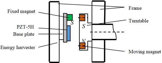
Therefore, this design uses magnetic excitation turntable structure, turntable evenly distributed a plurality of moving magnets. Fixed magnet is used as mass block at the end of the piezoelectric vibrator. During the rotating process of the turntable, the mutual forces, attraction and repulsion between the moving and stationary magnets can transform the rotating and torsional motions into reciprocating vibrations, and then the piezoelectric vibration energy harvester device is used to realize non-contact acquisition. The structural schematic diagram of the energy harvester device is shown in Fig. 1.
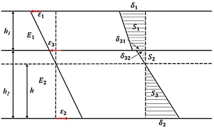
Considering that the order of magnitude of deformation of piezoelectric beam in torsional mode is much smaller than that of bending deformation, it can be ignored. Therefore, the deformation involved in this paper is all bending deformation. The stress distribution of the piezoelectric beam in the bending process is shown in Fig. 2 The stress distribution of the pure bending part of the composite beam is linear along the neutral layer, and there is a fault on the gluing bonding surface of the two materials. In the Fig. 2, the thickness of piezoelectric material and elastic substrate is and respectively, and the neutral layer is .
Fig. 2Bending stress distribution of piezoelectric beam
According to the geometric deformation relationship, it can be seen that:
According to Hooke’s law , the bending normal stress of each material in the composite beam, Young’s modulus of piezoelectric material , and Young’s modulus of elastic substrate material can be obtained, namely:
According to the pure bending static equilibrium of piezoelectric beam structure, the sum of internal stress vectors on both sides of neutral layer is zero:
The stress of each layer is obtained from the area formula:
The position of the neutral layer in bending deformation of piezoelectric beam can be obtained by simplifying the above formula:
is the width of the beam and the equivalent stiffness of the composite beam can be obtained from Eq. (6):
Specific symbols and their meanings are shown in Table 1.
Table 1Symbols and their meanings
Symbols | Meaning |
Total stress in piezoelectric sheet | |
Total stress in the substrate | |
Total stress in neutral layer | |
The thickness of neutral layer | |
The thickness of piezoelectric sheet | |
The thickness of substrate | |
Longitudinal positive strain in piezoelectric sheet | |
Longitudinal positive strain in the substrate | |
Longitudinal positive strain in neutral layer | |
Positive bending stress at the upper end of the piezoelectric sheet | |
Positive bending stress at the lower end of the base plate | |
Positive bending stress at the neutral layer of the piezoelectric sheet | |
Positive bending stress in the substrate at the neutral layer | |
Young’s modulus of piezoelectric material | |
Young’s modulus of substrate material | |
The width of the beam | |
The equivalent stiffness of the composite beam | |
Piezoelectric sheet aspect ratio |
When the equivalent stiffness of the composite beam is constant and the material of the upper part of the neutral layer is determined, that is, and are both constant, the farther the layer is from the neutral layer, the greater the deformation. So, the greater the thickness of the substrate, the greater the deformation of the piezoelectric layer.
Taking the movement law of the hoisting system of a mine in Anhui Province as the research background [23], the average speed of lifting the container is 5.9 m/s, with a 35 cm diameter roller cage shoe, then the rotation speed of the guide roller is 5.9/0.35 = 5.4 r/s. The moving magnets are evenly distributed on the right side of the hub of the roller cage shoe, and the energy harvester is installed 20 cm on the right side of the roller cage shoe. When working, the rotation of the roller cage shoe makes the force between the moving magnet and the stationary magnet change nonlinearly. Under the action of the magnet coupling force and the elastic force of the piezoelectric vibrator itself, the piezoelectric vibrator vibrates back and forth, and the bending deformation of the beam generates an alternating voltage on both sides of the piezoelectric sheet. The external circuit generates alternating current, which realizes non-contact rotational energy collection.
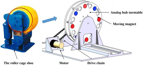
In order to facilitate the experimental exploration of the influence of the parameters of the energy harvester on the power generation performance, we simplified the structure of the roller cage shoe. The key rotating working structure is extracted, and the rotating test bench shown in Fig. 3 is designed to simulate the running state of the roller cage shoe. The turntable with a diameter of 20 cm simulates the hub part of the roller cage shoe, and 8 moving magnets are evenly distributed on the turntable. The stepping motor adjusts the speed so as to adjust the working frequency band of the energy harvester to keep at 0-50 Hz.
Fig. 3Gyromagnetic excitation test bed
3. Research on the structure of single energy harvester
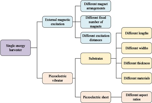
The exploration of energy harvester monomer structure mainly starts from two aspects: piezoelectric vibrator and external magnetic excitation, as shown in Fig. 4, which is the flow chart of the whole exploration of energy harvester monomer.
Fig. 4Monomer structure exploration flow chart of energy harvester
Piezoelectric material is the core part of electromechanical conversion. Its physical and chemical properties directly affect the conversion effect of the structure. In the experiment, the commonly used finished piezoelectric ceramic sheet with a thickness of 0.2 mm and a material of PZT-5H was selected. The installation of the piezoelectric vibrator the area does not exceed the magnetic excitation range. Fig. 5 shows the model of the piezoelectric plate, whose length-width ratio is the ratio between the length of the piezoelectric plate and the width of the piezoelectric plate, that is, .
Fig. 5Aspect ratio of piezoelectric plate
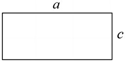
Therefore, under the condition that the material, thickness and installation range of piezoelectric materials are determined, the influence of different length-width ratios on the output voltage amplitude and peak frequency of rectangular power generation element piezoelectric ceramic plate with the same area is investigated.
Fig. 6Output voltage of piezoelectric chip with different aspect ratio
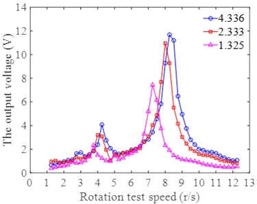
The area of the piezoelectric sheet determines the energy capture efficiency of the piezoelectric vibrator, and it is necessary to discuss the aspect ratio with a unified area. Fig. 6 shows the voltage amplitude frequency curves of piezoelectric sheets with different aspect ratios at different test speeds. In the range of aspect ratios from 1 to 5, with the increase of aspect ratio, the average output voltage increases significantly. increase in peak frequency. And the average output voltage when the aspect ratio is 4.336 is 2.77 V, which is 1.15 times that of the output voltage with an aspect ratio of 2.333, and 1.8 times that of the output voltage with an aspect ratio of 1.325. The piezoelectric sheet with a large aspect ratio has obvious advantages.
During the experiment, the vibration amplitude of the end of the piezoelectric vibrator with the smaller aspect ratio of the piezoelectric sheet is significantly larger. The first reason is that the stiffness of the piezoelectric sheet along the width section is proportional to the width. The greater the width, the greater the stiffness, resulting in a piezoelectric sheet with a smaller aspect ratio to have greater stiffness. The final manifestation is that the average deformation is small and the final output voltage is small. The second reason is: the stiffness of the piezoelectric sheet material is much greater than that of the elastic substrate material. For piezoelectric vibrators with the same substrate length, piezoelectric vibrators made of piezoelectric sheets with a larger length and width will have a short bonding area. Therefore, during the vibration process, the amplitude mainly depends on the stiffness of the cemented area, and the final performance is that the output voltage is large, the amplitude is small, and the peak frequency is high.
The research results show that the piezoelectric vibrator made of the piezoelectric sheet with a larger aspect ratio can not only effectively increase the output electric energy, but also reduce the vibration amplitude to a certain extent, which meets the design requirements.
Due to its fragile nature, piezoelectric elements need to be pasted on an elastic substrate for bending deformation to complete energy conversion. Therefore, the material of the elastic substrate has a great influence on the energy harvester performance of the energy harvester structure. The rotation speed of the roller cage shoe is 5.4 r/s, and the working frequency of the energy harvester is 0-50 Hz. In order to reduce the vibration amplitude of the structure and improve the low-amplitude vibration response sensitivity, it is necessary to study the material selection of the elastic substrate. At present, most of the commonly used energy harvester piezoelectric vibrator substrates are made of metal materials. Thin substrates are easily damaged, while thick substrates have small deformation. It can be seen from theoretical research that the greater the thickness of the substrate, the farther the piezoelectric layer is from the neutral layer, and the greater the deformation. Therefore, it is necessary to find a material with a certain thickness and strength that can maximize the efficiency of the piezoelectric sheet.
Fig. 7Stress distribution diagram of piezoelectric beams with different material substrates
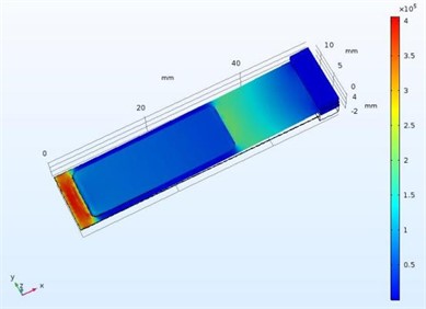
a) Copper
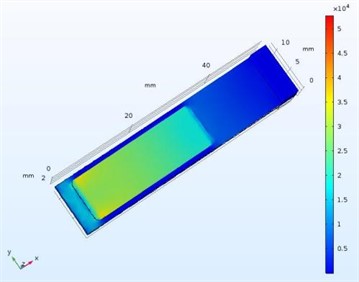
b) Acrylic
Compared with copper sheets, acrylic sheets have the characteristics of small stiffness, small amplitude, and large thickness. When the piezoelectric vibrator of the acrylic plate substrate undergoes tension and compression deformation, the surface tension of the piezoelectric plate is greater than that of the traditional copper substrate. Using the solid mechanics, piezoelectric material and circuit modules of the COMSOL multiphysics software, the statics and electromechanical coupling simulation analysis of the copper substrate piezoelectric vibrator of the same area and the acrylic substrate piezoelectric vibrator of different thicknesses are carried out. The boundary conditions are fixed-end fixed constraints, and conventional meshes are used to divide the study. It can be seen from the obtained surface stress distribution diagram of the piezoelectric vibrator in Fig. 7 that the acrylic substrate can make the bending deformation of the piezoelectric sheet more uniform than that of the traditional substrate. At the same time, Fig. 8 shows that the output voltage of the acrylic substrate reaches 22.3 V, and the utilization rate of the piezoelectric sheet is higher, which is twice that of the copper substrate. Therefore, in this study, acrylic material was selected as the piezoelectric vibrator substrate material.
Because the diameter of the rotating magnetic excitation turntable is only 20 cm, and the package size of the energy harvester structure needs to be as small as possible, that is, the structure size and vibration amplitude of the piezoelectric vibrator should not be too large. At the same time, the power output is as much as possible, and the utilization rate of the piezoelectric sheet is as large as possible. Therefore, it is necessary to comprehensively discuss the structure size of the substrate from a combination of theory and experiment to determine the optimal parameters.
The previous research shows that a larger aspect ratio of the piezoelectric sheet is beneficial to the design of the structure. In order to make the piezoelectric sheet fully fit on the substrate and reduce the width as much as possible, the article firstly explores the influence of the width of the substrate on the output voltage. It can be seen from the experimental results in Fig. 9 that the output voltage curves of piezoelectric vibrators with different substrate widths have the same trend of change, and the difference is not obvious. The output voltage difference between the three groups of substrate widths does not exceed 1 V. However, the increase in beam width increases the stiffness of the structure, resulting in an increase in the peak frequency of the structure. Taking all into consideration, the width of 12 mm is a suitable choice.
Fig. 8Output voltage of different substrate materials
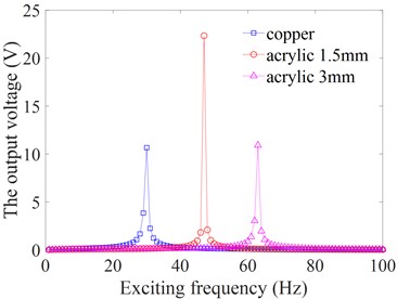
Fig. 9Output voltage of substrate with different widths
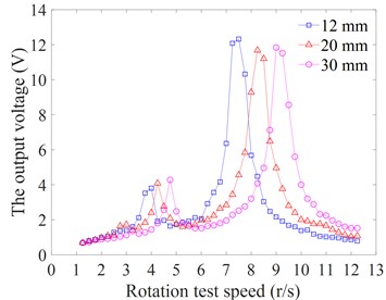
Fig. 10Output voltage of substrate with different length
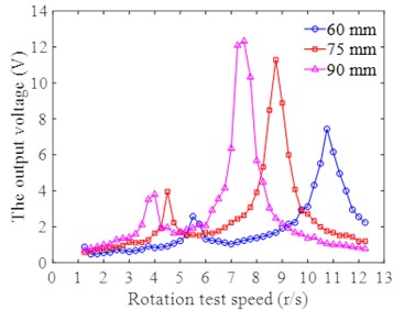
Fig. 11Output voltage of substrate of different thickness
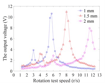
Fig. 10 is the output voltage curve of the piezoelectric vibrator with different length substrates, and the output peak value is 12.32 V at 90 mm. The experimental results show that the length has a great influence on the output voltage, and the increase of the length reduces the peak frequency of the output voltage and increases the voltage amplitude. However, during the experiment, it was found that when the length exceeds 90 mm, the voltage increase is significantly reduced, and the terminal amplitude is significantly increased. Because an excessively large length will lead to a larger unbonded area, the main deformation range will be transferred from the piezoelectric element to the unbonded elastic substrate, and the utilization rate of the piezoelectric sheet will be reduced. Therefore, the length should not be too large, and 90 mm is initially selected as the design value.
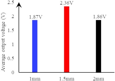
It can be seen from the output voltage curves of piezoelectric vibrators with different lengths and thicknesses shown in Fig. 11 that the output peaks of 1 mm and 1.5 mm are the same, but the increase of thickness makes the peak frequency of the output voltage gradually increase. However, in the effective output range, the output voltage with a thickness of 1.5 mm corresponds to a larger rotational speed range. In the average output voltage graph shown in Fig. 12, as the thickness increases, the average output voltage first increases and then decreases, indicating that the thickness has an optimal value. In view of the limited selection of substrate material thickness parameters, 1.5mm is initially selected as the design value.
After a series of optimization and comparison experiments, the structural parameters of the piezoelectric vibrator are finally obtained. The piezoelectric element is a PZT-5H piezoelectric ceramic sheet with a size of 52×12×0.2 mm (length×width×thickness), and the size of the acrylic elastic substrate is 90×12×1.5 mm.
Fig. 12Average output voltage of substrate of different thickness
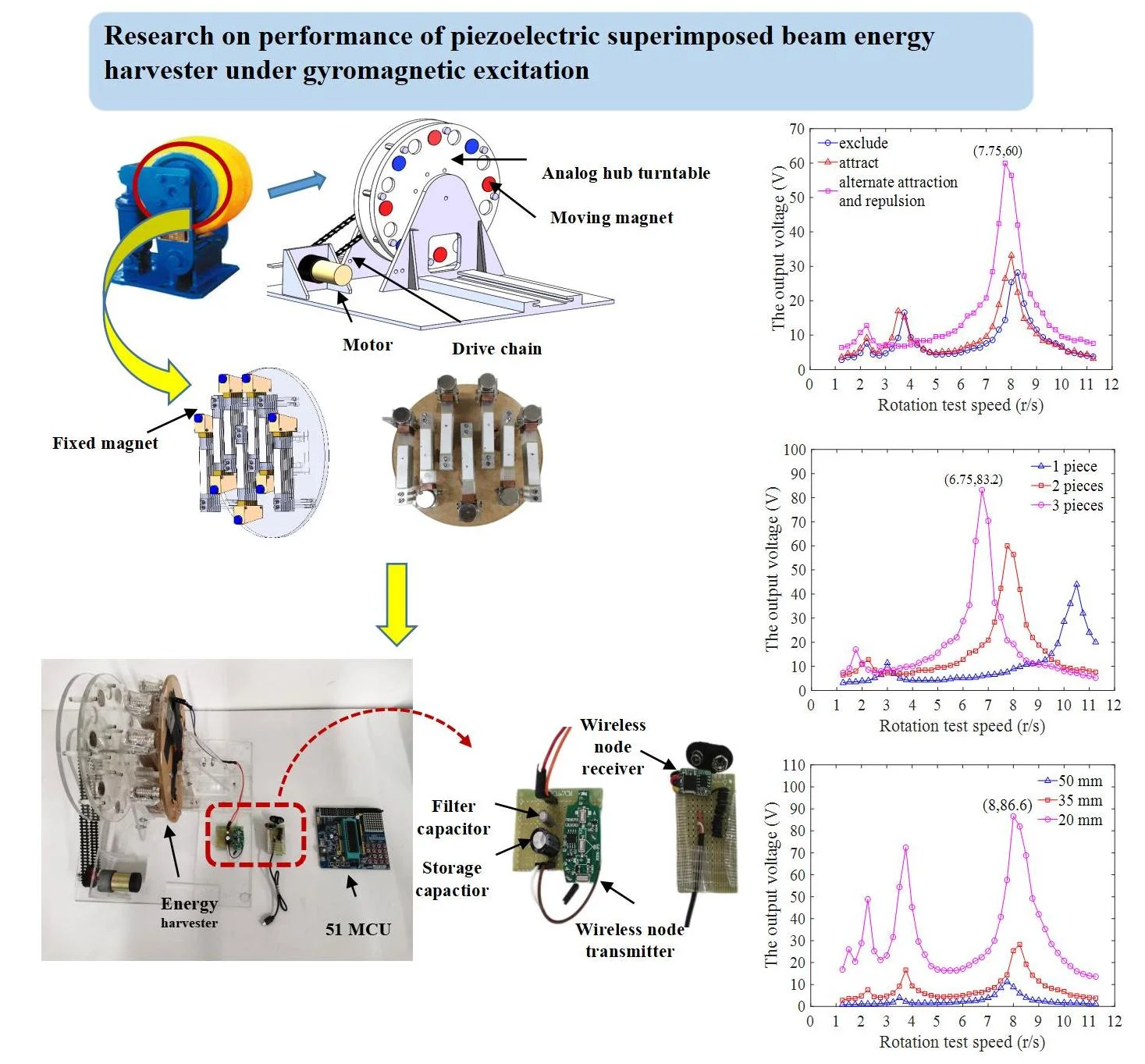
In the arrangement of the moving and stationary magnets, when the direction of the nonlinear magnetic force received by the piezoelectric vibrator is different, the force state is also different. When the structure is static, the opposite magnetic force of the same pole causes the piezoelectric sheet to be compressed or stretched. During the vibration process, the average deformation of the structure tends to be compressed or stretched, and the piezoelectric element is not fully utilized. To this end, this paper designs the situation where the N and S magnetic poles of the excitation magnets are alternately arranged. Fig. 13 shows the output voltages under the three magnet arrangements. It can be seen from the figure that the difference in the arrangement of the magnets does not change the peak voltage frequency. The maximum output voltage of the alternate arrangement reaches 60 V, and there are 4 rotational speed amplitudes greater than 30 V near the peak, which is better than the other two single arrangements. Way. The output voltage of alternating excitation is 1.92 times that of repulsive excitation and 1.69 times that of attractive excitation. The experimental results show that the alternate arrangement of N and S poles of the magnets increases the amplitude of the periodic excitation force on the excited magnet at the end of the piezoelectric vibrator to a certain extent, which can effectively improve the utilization rate of piezoelectric materials and obtain more power output.
Fig. 13Output voltage of different magnet arrangement mode
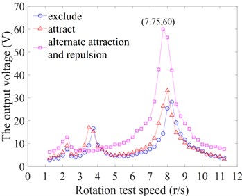
Fig. 14Output voltage of different fixed number of magnets
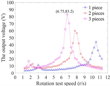
Increasing the excitation force can effectively improve the power output of the energy harvester. Therefore, the influences of fixed magnet number and excitation distance on acquisition voltage are investigated respectively. Fig. 14 shows the output of piezoelectric vibrators with different fixed magnet numbers. The increase in the number of magnets can greatly increase the output voltage. When the number of magnets is increased to 3, the maximum output voltage is as high as 83.2 V. At the same time, the increase in the number of magnets results in a substantial increase in the mass of the end, which reduces the frequency of the voltage peaks. The number of fixed magnets can be used to adjust the resonance frequency of the structure, and it should be properly selected and not too much.
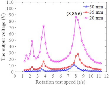
Fig. 15 shows the experimental results at different excitation distances. The experimental results show that when the excitation distance is reduced to 20 mm, the maximum output voltage is as high as 86.6 V, and there are as many as 7 test speeds where the output voltage near the peak is greater than 40 V. The reduction of the excitation distance makes the output voltage of the piezoelectric vibrator increase sharply without changing the peak frequency. This parameter can be used to adjust the output voltage. However, if the distance is too close, it is easy to cause structural interference and collision, so it should be selected reasonably according to the output needs.
Fig. 15Output voltages at different excitation distances
4. Research on the structure of array energy harvester
In this paper, the output characteristics of the single-structure piezoelectric vibrator are analyzed, but due to the material and size, the output power of the single-structure piezoelectric vibrator is limited, and an array structure design is required. In order to improve the power output while reducing the occupied area of the array structure, the limited space is effectively utilized. This paper does not use the common horizontal array structure, and proposes a vertical array superimposed beam structure design, and explores the influence of the parameters of the array structure on the power output.
In order to ensure that the piezoelectric vibrators at different positions in the array structure have vibration synchronization, the ends of the piezoelectric vibrators need to be connected. In the transverse array, the connection is usually made by sharing the end mass, but the end mass in this way can swing freely. However, the end connecting structure in the vertical array structure can only be translated, so the piezoelectric vibrator will be subjected to an additional reverse bending moment. Theoretically, the reverse bending moment will hinder the vibration of the piezoelectric vibrator, resulting in a decrease in the output voltage. For this reason, the end hinge structure is designed this time to eliminate the influence of the reverse bending moment at the end. In order to verify the influence of the terminal bending moment generated by the fixed terminal on the output voltage and the acquisition effect of the improved terminal hinged structure, the fixed terminal and hinged terminal array structures shown in Fig. 16 were designed for experiments.
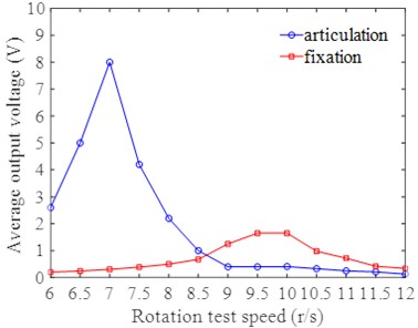
The experimental results are shown in Fig. 17. It can be clearly seen from the figure that the peak value of the test output voltage at the connected end of the articulated structure is much greater than that at the consolidated end, and the voltage peak frequency of articulated structure is obviously lower than that of consolidated structure. The reason for the above results can be explained as the reverse deformation trend at the end of the consolidated structure increases the equivalent stiffness of the structure and makes the resonance frequency of the structure higher.
Fig. 16Connection mode of terminal array
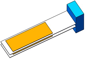
a) Consolidated end
b) Articulated end
Fig. 17Double sheet array free end connection mode
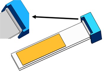
Although the end connection of the hinged structure can effectively overcome the influence of the reverse bending moment at the end. However, when making a three-layer superimposed array structure, due to a certain slight error in installation, the center of the hinged end of the three-layer piezoelectric vibrator is not in a straight line. Interference phenomenon that causes the intermediate layer to be stretched or squeezed. This situation will also strengthen the structural rigidity to a certain extent, which is not conducive to the vibration of the array. In order to improve the above structure, eliminate the interference of the intermediate layer, and make full use of the space, this paper proposes a hybrid connection method. The top and bottom two layers of piezoelectric vibrators are connected by hinges. In order to avoid manufacturing errors, the beams of the middle layer are subjected to interference effects such as tension and compression, resulting in additional stiffness. During the movement of the ends of each layer in the middle of the superimposed beam, a small amount of relative sliding can occur with the mass block support, thereby reducing the structural rigidity and ensuring the consistency of the structural vibration of the ends of each piezoelectric vibrator. The end connection makes a plurality of piezoelectric vibrators form an integral superimposed beam, and then a mass block for adjusting the overall natural frequency is placed on the mass block support at the end of the superimposed beam. As shown in Fig. 18, a comparative experiment was carried out.
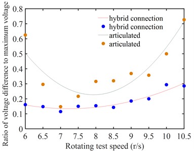
It can be seen from Fig. 19 that the output voltage of the piezoelectric vibrator of each layer under the hinged structure is lower than the output voltage of each layer under the hybrid connection. And the peak frequency of the output voltage of the hinged structure is higher than that of the hybrid connection, and the experimental results are highly consistent with the predicted results. At the same time, the voltage output of the three-piece hinged array structure is relatively scattered, while the output voltage of the hybrid connection terminal is relatively concentrated. Fig. 20 shows the ratio of the difference between the maximum peak value and the minimum peak value to the maximum peak value among the three output voltage peaks at the same test speed. This ratio reflects the consistency of the vibration of the three piezoelectric vibrators to a certain extent. The ratio of the mixed connection at the ends is generally smaller than that of the three hinged ends, and the ratio of the mixed connection ends is more stable. The experimental results fully demonstrate the superiority of the hybrid connection method.
Fig. 18End hybrid connection mode
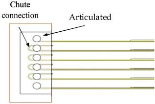
a) 2D map
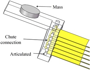
b) 3D map
Fig. 19The output voltage of three-chip array structure connection mode
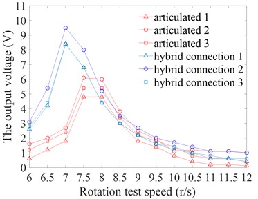
Fig. 20The output peak ratio of three-chip array structure
Among the array structure parameters, the array spacing directly affects the overall size of the array structure. Therefore, on the basis of determining the end connection structure, the array spacing was experimentally explored. The research results are shown in Fig. 21 Combined with the experimental results, it can be seen that with the increase of the array spacing, the fluctuation range of the test speed corresponding to the peak voltage is not large, but the maximum output voltage continues to decrease. Moreover, during the experiment, the continuous increase of the array spacing will cause the terminal connection structure to deflect slightly during the translation process, which will cause the upper and lower layers to deform out of synchronization, or even interfere with each other, which will reduce the output voltage. However, the overall size parameters of the structure remain unchanged, so the voltage peak frequency is basically unchanged. Therefore, under the premise of ensuring that the beams of each layer do not interfere with each other, the array spacing should be as small as possible, which can not only ensure higher voltage output, higher vibration consistency but also reduce the structure size. Therefore, the output response is best when the vertical array spacing is 1.5 mm.
Fig. 21The output voltages at different array spacing
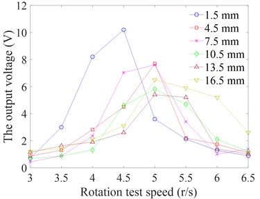
Fig. 22Average output voltage of different array numbers
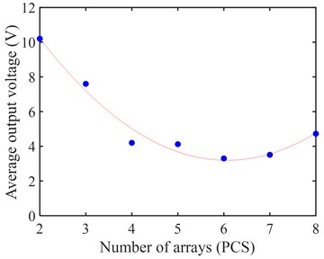
The number of structure arrays is a decisive factor in the output power of the structure. On the basis of the above conclusions of the array parameters, the effects of different numbers of vertically stacked arrays on the output voltage and structural vibration consistency were explored. It can be seen from Fig. 22 that with the continuous increase of the number of arrays, the overall average output voltage has a decreasing trend, indicating that the increase of the number of arrays will make the consistency of structural vibration worse. It means that some piezoelectric vibrators cannot fully function during the vibration process, and the number of arrays is too small to take full advantage of the structure.
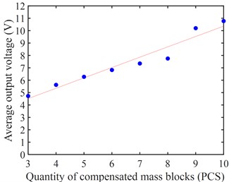
The increase in the number of arrays increases the overall stiffness of the structure, as shown in Fig. 23. The peak frequency of the output voltage increases approximately linearly with the number of arrays. The increase in stiffness reduces the structural amplitude to a certain extent, which is the main factor for the reduction of the average output voltage. In order to balance the increase in stiffness caused by the increase in the number of arrays, it is necessary to conduct mass compensation experiments on the array structure. Combined with the utilization rate and compact structure of the piezoelectric vibrator, the number of vertical stacking arrays is selected to be 8, and the mass compensation experiment is carried out. In the experiment, a magnet is used as a mass block, which increases the mass of the end and also increases the nonlinear excitation magnetic force, thereby improving the power output. Fig. 24 is the trend curve of the maximum output voltage of each layer in the array under different compensations. It can be seen from the figure that with the increase of compensation mass, the average output voltage increases linearly with the increase of compensation mass. It reflects that the overall structure has good vibration consistency. As can be seen in Fig. 25, the peak frequency of the output voltage decreases linearly with the increase of the compensation quality, achieving a good increase and frequency reduction effect.
Fig. 23The peak frequency of different array numbers
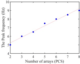
Fig. 24Average output voltages for different compensation masses
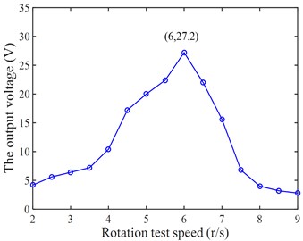
After determining the number of arrays and compensation quality parameters, we measured the output voltage of the nonlinear gyromagnetic excitation piezoelectric superimposed beam energy harvester in the range of 2-9 r/s rotation test speed. The results are shown in Fig. 26 The peak frequency of the overall output voltage of the energy harvester is 6 r/s, which is more consistent with the working speed of the tank ear in the research background of 5.4 r/s. The effective speed range is 5-6 r/s, and the output is stable and at a high level. The output range is 20-27.2 V. The stable output voltage ensures the stable operation of subsequent micro-power devices, which has certain research significance.
Fig. 25The peak frequency of different compensated masses
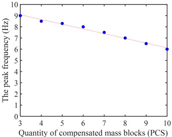
Fig. 26Output voltage of beam array in mixed connection mode
5. Acquisition performance of piezoelectric superimposed beam lateral array structure
Considering this application background, the lateral area of the energy harvester can continue to be used. In order to further improve the output power, the nonlinear piezoelectric superimposed beam energy harvester under gyromagnetic excitation is arranged in a transverse array. The overall acquisition performance was experimentally explored and its output was impedance matched to explore optimal workload and maximum output power.
Fig. 27Piezoelectric superimposed beam lateral array structure
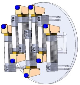
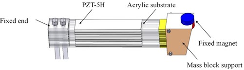
Fig. 27 shows the structure of the nonlinear piezoelectric superimposed beam energy harvester under gyromagnetic excitation array structure, each energy harvester is evenly distributed on the surface of the acrylic material fixed plate. Make full use of the effective space and combine the circular arrangement of the moving magnets, and arrange 7 groups horizontally to obtain the best output power. Two common array structure circuit connection modes are series output of rectifier circuit and parallel output of rectifier circuit. The series output circuit diagram of the rectifier circuit of the energy trap is shown in Fig. 28(a). The output voltage of each piezoelectric vibrator is connected in series, and a voltage stabilizing capacitor is connected in parallel at the total output to reduce voltage fluctuation. Finally, the output electric energy is stored in the energy storage capacitor. The parallel output principle of the rectifier circuit of the energy trap is shown in Fig. 28(b) to ensure that the rectifier output terminals of each piezoelectric vibrator are connected in the same polarity. After parallel output, the structure is similar to that of the series connection, and the terminal is connected in parallel with the voltage stabilizing capacitor and energy storage capacitor.
Fig. 28Parallel output schematic diagram of rectifier circuit of energy harvester
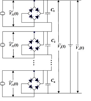
a) Schematic diagram of series output of energy capture rectifier circuit
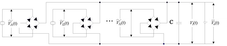
b) Schematic diagram of parallel output of energy capture rectifier circuit
In order to obtain more conveniently and quickly, more suitable for the rectification circuit connection mode of the superposed beam type gyromagnetic excitation piezoelectric energy capture array structure proposed by us, and reduce the use of experimental materials, we use or CAD software to conduct circuit simulation to simulate the output voltage and load power of different load resistance values under the two connection modes.
Fig. 29Output power of different loads in series and parallel output mode
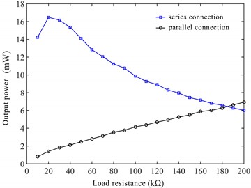
First, the circuit is drawn in the software, the solution parameters are set, the external load RL is parametrically scanned, and the voltage at both ends of the load is recorded. Finally, after post-processing the data, the maximum output voltage and power corresponding to each load resistance in the series and parallel modes are obtained, as shown in Fig. 29.
In Fig. 29, when the load resistance is less than 180 k Ω, the advantage of parallel output is obvious; Therefore, LX10M ultra small patch rectifier bridge is selected to parallelize each independent standard rectifier circuit.
The parallel output of the energy harvester is accompanied by changes in the capacitance value of the piezoelectric material and the fluctuation frequency of the output voltage, which is comprehensively manifested as a change in the equivalent impedance. When the external load is connected, the power consumption of the load also changes with the change of the impedance of the energy harvester array, and the load power directly determines the utilization rate of the energy converted by the energy harvester. Therefore, it is necessary to carry out a load matching experiment on the energy harvester array. The experimental setup is shown in Fig. 30.
Fig. 30Experimental device drawing of energy harvester (photo taken by Tianbing Ma on April 5th, 2022, at State Key Laboratory of Mining Response and Disaster Prevention and Control in Deep Coal Mines, Anhui University of Science and Technology)
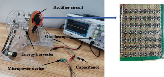
Fig. 31 is the output power amplitude frequency curve for different load sizes. As the load resistance increases, the output power first increases and then decreases, and there is an optimal value, which is not the greater the power consumed. The change of load does not change the peak frequency. At 6 r/s rotation speed, the output power reaches 11.236 mW at the maximum when externally connected to 10 kΩ, and even at 0.5 kΩ, the minimum output power reaches 1.095 mW. Compared with the paper of Zou [11], we have more advantages, as shown in Table 2.
Fig. 31Parallel output power curves of different loads
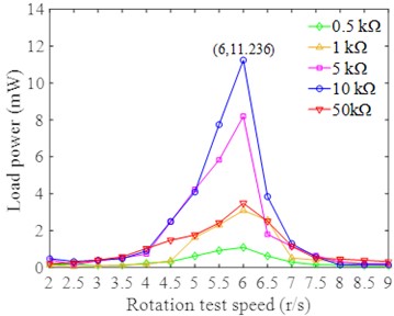
Table 2Comparison with results of other papers
This article | Minimum power | 1.095 mW | Maximum power | 11.236 mW |
Other article | Minimum power | 535.3 uW | Maximum power | 564 uW |
6. Power supply test of energy harvester
The goal of this structural design is to realize the rotational energy conversion of the rotating mechanism such as the roller cage shoe, to supply energy for some low-power sensors, and to reduce the use of chemical batteries and the frequency of manual battery replacement. From the experimental research in the previous part, we obtained the output power of the nonlinear piezoelectric superimposed beam energy harvester under gyromagnetic excitation array structure after optimizing the parameters. The theoretical output of 11.236 mW can meet the energy supply requirements of some micro-power devices, but still experiments are required to test its accuracy. This time, the micro-power wireless node is used as the experimental verification object. The specific execution program has been programmed in it, and it is controlled by the on-off command. The working voltage is 3.7-12 V, and the normal transmission distance is 30 m.
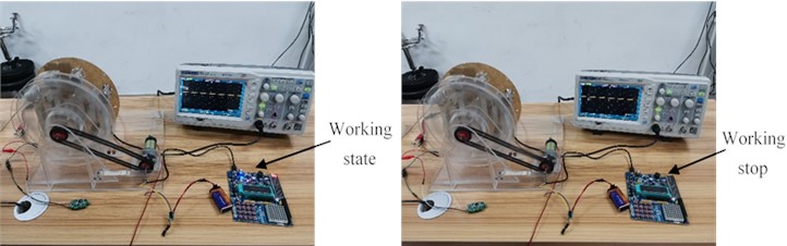
The gyromagnetic excitation test bench works to simulate the rotation state of the roller cage shoe. The energy harvester is connected to a 450 μF 16 V temporary energy storage capacitor to collect rotating energy. The positive and negative poles of the capacitor are connected to both ends of the wireless transmitter module for power supply. Both ends of the wireless receiving module are normally powered and connected to the 51 single-chip microcomputer. As shown in Fig. 32 and Fig. 33, the rotational energy collected by the energy harvester can provide normal power for the wireless transmitter. Press the open command button, the receiver responds, and the single-chip microcomputer starts to work. Press the close command button, and the single-chip microcomputer stops working. It can be seen that the nonlinear piezoelectric superimposed beam energy harvester under gyromagnetic excitation can realize the self-powering function of the wireless sensor.
Fig. 32Wireless node self-powered device
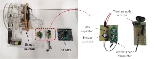
Fig. 33Wireless node working status (photos taken by Tianbing Ma on April 5th, 2022, at State Key Laboratory of Mining Response and Disaster Prevention and Control in Deep Coal Mines, Anhui University of Science and Technology)
7. Conclusions
In this paper, a piezoelectric superimposition beam energy trap with nonlinear gyromagnetic excitation is proposed for energy acquisition of the rotary mechanism of the can ear. The main source of vibration excitation is the nonlinear coupling force between the moving and fixed magnets. It is proposed for the first time to use acrylic materials instead of traditional metals as the base plate, which improves the utilization of piezoelectric chips and makes the average output voltage of piezoelectric vibrator as high as 2.36 V. At the same time, in order to improve the output power, the piezoelectric vibrator is hinged at the upper and lower layers, connected by the middle layer chute, and the transverse array of piezoelectric superimposed beam energy capture device excited by nonlinear gyromagnetism is arranged. When the number of arrays is 7 and the external load is 10 k Ω, the maximum real-time output power reaches 11.236 mW. When simulating the working state of the tank ear, the nonlinear gyromagnetic excitation piezoelectric superposition beam energy trap can realize the power supply to the wireless transmitting node, and the wireless transmission distance is greater than 30 m, which has strong practical application value.
References
-
H.-X. Zou et al., “Mechanical modulations for enhancing energy harvesting: Principles, methods and applications,” Applied Energy, Vol. 255, p. 113871, Dec. 2019, https://doi.org/10.1016/j.apenergy.2019.113871
-
X. Mei, S. Zhou, Z. Yang, T. Kaizuka, and K. Nakano, “A tri-stable energy harvester in rotational motion: Modeling, theoretical analyses and experiments,” Journal of Sound and Vibration, Vol. 469, p. 115142, Mar. 2020, https://doi.org/10.1016/j.jsv.2019.115142
-
H. Shi, Z. Liu, and X. Mei, “Overview of human walking induced energy harvesting technologies and its possibility for walking robotics,” Energies, vol. 13, no. 1, p. 86, dec. 2019, https://doi.org/10.3390/en13010086
-
J. Wang, S. Zhou, Z. Zhang, and D. Yurchenko, “High-performance piezoelectric wind energy harvester with Y-shaped attachments,” Energy Conversion and Management, Vol. 181, pp. 645–652, Feb. 2019, https://doi.org/10.1016/j.enconman.2018.12.034
-
L. M. Oliveira and J. J. Rodrigues, “Wireless sensor networks: a survey on environmental monitoring,” Journal of Communications, Vol. 6, No. 2, pp. 143–151, Apr. 2011, https://doi.org/10.4304/jcm.6.2.143-151
-
L. Zhao and Y. Yang, “Comparison of four electrical interfacing circuits in wind energy harvesting,” Sensors and Actuators A: Physical, Vol. 261, pp. 117–129, Jul. 2017, https://doi.org/10.1016/j.sna.2017.04.035
-
Y. Kuang, Z. Yang, and M. Zhu, “Design and characterisation of a piezoelectric knee-joint energy harvester with frequency up-conversion through magnetic plucking,” Smart Materials and Structures, Vol. 25, No. 8, p. 085029, Aug. 2016, https://doi.org/10.1088/0964-1726/25/8/085029
-
D. Al-Yafeai, T. Darabseh, and A.-H. I. Mourad, “A state-of-the-art review of car suspension-based piezoelectric energy harvesting systems,” Energies, Vol. 13, No. 9, p. 2336, May 2020, https://doi.org/10.3390/en13092336
-
H. Fu and E. M. Yeatman, “A methodology for low-speed broadband rotational energy harvesting using piezoelectric transduction and frequency up-conversion,” Energy, Vol. 125, pp. 152–161, Apr. 2017, https://doi.org/10.1016/j.energy.2017.02.115
-
P. Micek and D. Grzybek, “Experimental analysis of the arrays of macro fiber composite patches for rotational piezoelectric energy harvesting from a shaft,” Energies, Vol. 14, No. 16, p. 4815, Aug. 2021, https://doi.org/10.3390/en14164815
-
H.-X. Zou et al., “Design and experimental investigation of a magnetically coupled vibration energy harvester using two inverted piezoelectric cantilever beams for rotational motion,” Energy Conversion and Management, Vol. 148, pp. 1391–1398, Sep. 2017, https://doi.org/10.1016/j.enconman.2017.07.005
-
J. Zhang, Z. Fang, C. Shu, J. Zhang, Q. Zhang, and C. Li, “A rotational piezoelectric energy harvester for efficient wind energy harvesting,” Sensors and Actuators A: Physical, Vol. 262, pp. 123–129, Aug. 2017, https://doi.org/10.1016/j.sna.2017.05.027
-
H.-X. Zou et al., “Design, modeling and experimental investigation of a magnetically coupled flextensional rotation energy harvester,” Smart Materials and Structures, Vol. 26, No. 11, p. 115023, Nov. 2017, https://doi.org/10.1088/1361-665x/aa8eb8
-
Y. Zhang, R. Zheng, K. Nakano, and M. P. Cartmell, “Stabilising high energy orbit oscillations by the utilisation of centrifugal effects for rotating-tyre-induced energy harvesting,” Applied Physics Letters, Vol. 112, No. 14, p. 143901, Apr. 2018, https://doi.org/10.1063/1.5019907
-
Z. Liang et al., “Optimization of cantilevered piezoelectric energy harvester with a fixed resonance frequency,” Science China Technological Sciences, Vol. 57, No. 6, pp. 1093–1100, Jun. 2014, https://doi.org/10.1007/s11431-014-5556-7
-
M. Guan and W.-H. Liao, “Design and analysis of a piezoelectric energy harvester for rotational motion system,” Energy Conversion and Management, Vol. 111, pp. 239–244, Mar. 2016, https://doi.org/10.1016/j.enconman.2015.12.061
-
W. Yu-Jen, C. Tsung-Yi, and Y. Jui-Hsin, “Design and kinetic analysis of piezoelectric energy harvesters with self-adjusting resonant frequency,” Smart Materials and Structures, Vol. 26, No. 9, p. 095037, Sep. 2017, https://doi.org/10.1088/1361-665x/aa7ad6
-
X. Fu and W.-H. Liao, “Modeling and analysis of piezoelectric energy harvesting with dynamic plucking mechanism,” Journal of Vibration and Acoustics, Vol. 141, No. 3, p. 03100, Jun. 2019, https://doi.org/10.1115/1.4042002
-
J. Kan, J. Fu, S. Wang, Z. Zhang, S. Chen, and C. Yang, “Study on a piezo-disk energy harvester excited by rotary magnets,” Energy, Vol. 122, pp. 62–69, Mar. 2017, https://doi.org/10.1016/j.energy.2017.01.059
-
K. B. Singh, V. Bedekar, S. Taheri, and S. Priya, “Piezoelectric vibration energy harvesting system with an adaptive frequency tuning mechanism for intelligent tires,” Mechatronics, Vol. 22, No. 7, pp. 970–988, Oct. 2012, https://doi.org/10.1016/j.mechatronics.2012.06.006
-
K. F. Wang, B. L. Wang, and J. E. Li, “Electromechanical model of layered flexoelectric energy harvesters with strain gradient effect,” Energy, Vol. 191, p. 116560, Jan. 2020, https://doi.org/10.1016/j.energy.2019.116560
-
S. Saadon and O. Sidek, “A review of vibration-based MEMS piezoelectric energy harvesters,” Energy Conversion and Management, Vol. 52, No. 1, pp. 500–504, Jan. 2011, https://doi.org/10.1016/j.enconman.2010.07.024
-
C. Tang et al., “Impact cushioning device of wireless sensor node for emergency rescue system in underground coal mine,” Advances in Mechanical Engineering, Vol. 10, No. 1, p. 168781401775248, Jan. 2018, https://doi.org/10.1177/1687814017752481
About this article

The authors would like to thank the State Key Laboratory of Mining Response and Disaster Prevention and Control in Deep Coal Mines, Anhui University of Science and Technology and Anhui University of Science and Technology.
The research was funded by the University Natural Science Research Program of Anhui Province under Grant KJ2020A0281, the Anhui Provincial Natural Science Foundation under Grant 2008085ME178, the Top Talent Program of Anhui Province under Grant gxbjZD202020063, the Anhui Provincial Key Research and Development Plan under Grant 202104a07020005 and the Supported by the Independent Project of State Key Laboratory under Grant SKLMRDPC20ZZ01 and the University Synergy Innovation Program of Anhui Province under Grant GXXT-2022-019.
The datasets generated during and/or analyzed during the current study are available from the corresponding author on reasonable request.
Conceptualization: Fei Du and Tianbing Ma; Methodology: Menghan Yin; Software: Nengyong Wang; Validation: Nengyong Wang; Formal analysis: Zhihao Zhang; Resources: Zhihao Zhang; Data curation: Nengyong Wang; Writing-original draft preparation: Nengyong Wang; Writing-review and editing: Fei Du; Supervision: Zhihao Zhang; Funding acquisition: Tianbing Ma. All authors have read and agreed to the published version of the manuscript.
The authors declare that they have no conflict of interest.
