Abstract
Energy Harvesting (EH) is the science that studies the conversion of energy dispersed in environment into a different and more useful form of energy, mainly the electrical one. In recent years, several energy-harvesting devices using piezoelectric materials have been developed to transform environmental vibrations into electrical energy. Since most piezoelectric energy harvesters are in form of cantilevered beams, the aim of this paper is to model and simulate a cantilever beam as energy harvester from wind-induced vibrations. The behavior of a cantilever beam with a fixed configuration (dimensions, materials, boundaries and shape) subjected to wind pressure was observed in an experimental apparatus and the reaction of the same device was described with a mathematical model based on piezoelectric constitutive equations and mechanical equilibrium equations. The device was simulated with the Comsol Multiphysics software that implements the equations of the mathematical model by the Finite Element Method (FEM). The experimental results were used to validate the simulation environment and their comparison with calculated results allows an appropriate choice of the most suitable piezoelectric material, among natural crystals, piezo ceramics, piezo polymers and piezocomposites, for this type of cantilever.
1. Introduction
In recent years, the increasing production of low-power electronic devices, such as wireless sensors, has been accompanied by increased research about their powering with something different from the traditional batteries, whose recharging or replacement is often expensive or very difficult and sometimes impossible because of their placing. The reduced life of batteries influences and reduces the life of electronic devices when they could still work, having a natural life longer than that of their suppliers [1, 2].
A solution to the described problem has been proposed by Energy Harvesting (EH), defined by Heung Soo et al. as the process that tries to capture “minute amounts of energy from one or more of the surrounding energy sources, accumulating them and storing them for later use” [2].
Energy is wasted everywhere in the environment and according to Sirohi and Mahadik [3] there are several ways to harvest energy, such as the energy harvested from base-excited vibrations, or flow induced vibrations or flutter due to wind flow. This enables vibrations to become an “endless” source of not expensive and non-polluting energy because of the conversion of kinetic energy into electrical one. Piezoelectric materials well fit with this purpose because of their natural property of producing electrical potential when they are mechanically stressed and piezoelectric transducers are more suitable than their electrostatic and electromagnetic counterparts for the conversion kinetic to electric energy because of their higher energy density [4, 5]. Moreover, they have a simple structure and often they have the form of unimorph (with one piezoelectric layer) or bimorph (with two piezoelectric layers) cantilevered beams: the harvester beam is located on a vibrating host structure and the dynamic strain induced in the piezoceramic layers results in an alternating voltage output across their electrodes [6].
Wind is an important renewable energy source, available everywhere in the world and each wind energy harvester can be used and applied universally. EH researchers have been designed different solutions to exploit wind energy, using piezoelectric devices. In 2013, a panel made of wind sensors to convert the wind-induced vibrations into electric energy, called ‘Vibro-Wind’ technology, was proposed and realized by a group of researchers at the Cornell University [7]. Yang et al. presented a rotational piezoelectric energy harvester in which impact-induced resonance is used to enable effective excitation of the intrinsic mode of vibration of piezoelectric cantilevers: this implies an optimum deformation of cantilevers themselves, which is beneficial for the transformation of kinetic into electric energy. The small windmill was realized with piezoelectric bimorph cantilevers locked at one end and placed as a polygon, which has inside some elastic balls. When the wind causes the rotation of device, the balls strike the piezoelectric layers, producing electric potential because of the piezoelectric effect [4]. In the same field of small-scale windmills Rezaei et al. proposed a topology for piezoelectric EH consisting of a lift-based wind turbine and a piezoelectric beam with contactless vibration mechanism. This structure enables to harvest energy from a wide range of wind speeds [8].
The aim of this paper is to validate the modeling and simulation of a wind-stressed piezoelectric cantilever beam, making a comparison between experimental and calculated data. The former ones were detected on a cantilever beam made of Polyvinylidene Fluoride (PVDF) and silver and subjected to wind force; the latter data were obtained from a software simulation of the same device. The validated model can be used to enlarge the number and the range of case studies so enabling the analysis of situations that are difficult to realize experimentally.
In the first section, the paper describes the approach used to validate the simulation environment: the equations and the software used to simulate the behavior of cantilever under wind effect and all elements useful to simulation, such as boundary conditions, are qualified. The section ends with the description of experimental apparatus and the exhibition of numerical results obtained. The last section of paper proposes a comparison between results produced by different materials, belonging to natural crystals, piezo ceramics, piezo polymers and piezocomposite, in order to choose the optimal piezoelectric material for this kind of cantilever. This last study is carried out by characterizing the constitutive matrices for the piezoelectric material in testing and implementing the equations of the mathematical model for each different material.
2. Model validation
2.1. Mathematic model
The mechanical equilibrium equations are useful to describe the behavior of a cantilever beam that experiences a deformation because of wind pressure and develops electric potential:
where is the stress, is the volume force, is the surface force, is the pressure, is the normal vector to surface where pressure is applied. The direct piezoelectric effect, due to the PVDF layer, is mathematically described by constitutive equations of piezoelectric materials expressed in the stress-charge form:
where the superscript denotes the transpose matrix, is the elasticity matrix (evaluated at constant electric field); is the piezoelectric stress matrix or coupling matrix, and is the dielectric matrix (evaluated at constant mechanical strain ) of the piezoelectric material and is the electric displacement vector.
2.2. Comsol Multiphysics simulations
Simulations described in this paper have been implemented using Comsol Multiphysics, a general-purpose software platform, based on advanced numerical methods, for modeling and simulating physics-based problems. Comsol Multiphysics reproduced in simulation all situations analyzed with the experimental apparatus, using the previous Eqs. (1), (2), (3) and (4). The cantilever used was built with the same shape, dimensions and materials of that used in experimental apparatus. Fig. 1, realized with Comsol Multiphysics, shows the geometry of cantilever in initial status, without any pressure applied.
Fig. 1The simulated cantilever (Comsol Multiphysics, all dimensions in millimeters)
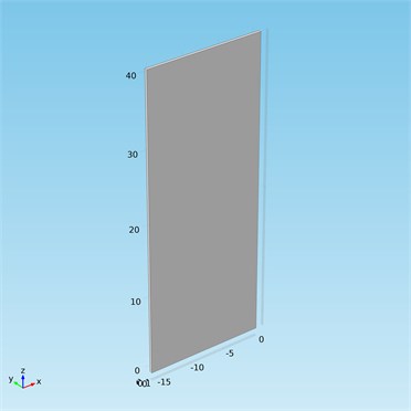
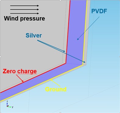
Fig. 2Boundary conditions
In order to solve Eqs. (1), (2), (3) and (4) and to study piezoelectric materials opportunely, Comsol Multiphysics needs all coefficients of matrices , and , as input data. PVDF coefficients were calculated for this work expressly, using an appropriate algorithm. The relations between the coefficients of the four sets of constitutive equations for piezoelectric materials, proposed by IEEE Standard of Piezoelectricity [9], were applied to the coefficients known in literature [10] and the algorithm provided the unknown coefficients. Despite the approximations due to numerical computation, the obtained results had an overall error considerably low and PVDF coefficients used for simulations described in this paper are reported in Eq. (5), (6) and (7), with appropriate units. PVDF belongs to the mm2 crystal class of the orthorhombic system so its constitutive matrices have 17 independent coefficients.
Since the analysis involves piezoelectric material, there are two different kinds of boundary conditions to set: mechanical and electrical ones, depicted in Fig. 2. In terms of mechanical conditions, the device is ‘free’ to move under loads caused by wind, except for its lowest surface that is locked. For the electric boundary conditions, the cantilever has at ‘zero charge’ the nearest surface to silver layer where wind pressure is applied and at ‘ground’ the nearest surface to the other silver layer.
2.3. Experimental apparatus
Fig. 3-4 show the cantilever beam used in the experimental apparatus and its pattern. It is a unimorph piezoelectric device because it has only one layer of PVDF put like a sandwich between two layers of silver ink.
Fig. 3Meas LDT1-028k transducer made of PVDF and silver
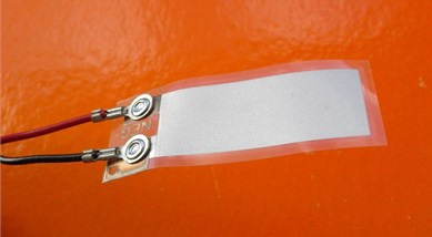
Fig. 4Pattern of cantilever beam
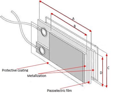
The screen-printed electrodes were supplied with a thin protective coating over the active electrode area to prevent oxidation to the top surface of the silver ink. Its dimensions and properties (Table 1) are provided by its manufacturer [11]. The thickness of protective coating is considered negligible.
Wind bumps the cantilever that reacts deforming itself and generating electrical energy because of the direct piezoelectric effect of PVDF.
Table 1Dimensions and properties of the cantilever beam
Parameter | Value | Unit | |
Metallic beam | Short length B | 30 | mm |
Width | 12 | mm | |
Thickness | 6+6 | µm | |
PVDF | Length A | 41 | mm |
Width | 12 | mm | |
Thickness | 28 | µm | |
Piezo strain constant | 23×10-12 | C/N | |
Piezo strain constant | –33×10-12 | C/N | |
Piezo strain constant | 216×10-3 | Vm/N | |
Piezo strain constant | –330×10-3 | Vm/N | |
Electromechanical coupling factor | 0.12 | ||
Plastic coating | Thickness | Negligible |
Fig. 5Cantilever on anemometer and wind direction
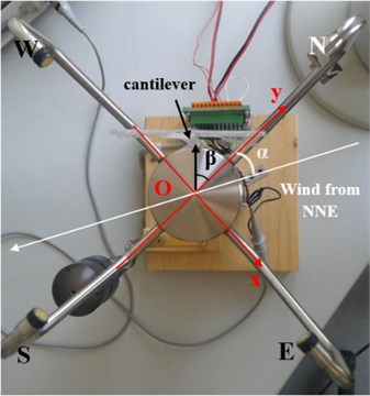
The experimental apparatus was also composed of an ultrasound-based digital anemometer (a Thies Clima’s model US2D, in Fig. 5 as seen from above), an oscilloscope and a pc. A purposely-developed C# .NET application provides velocity and direction of wind impressed on cantilever and, at the same time, it provides the root mean square (RMS) value, the minimum and the maximum value of voltage detected by a digital oscilloscope connected to the cantilever output.
In Fig. 5 angle 45° indicates the position of cantilever relative to north.
To convert measured values of wind speed into values of wind pressure useful for simulation, Eqs. (8) and (9) proposed by the IEEE National Electrical Safety Code [12] were used:
where wind pressure is expressed in Pound-force per square foot in Eq. (8) and in Pascal in Eq. (9), while is the wind velocity expressed in mile per hour in Eq. (8) and in meters per second in Eq. (9).
2.4. Numerical results
In the experimental setup, the induced electrical potential was analyzed in function of different initial wind velocity whose values are shown in Table 2. In the simulated environment, the wind velocity of the experimental situation was converted in wind pressure using Eq. (9). Table 2 provides all values of measured wind velocity, calculated wind pressure and the RMS value of developed electric potential, both measured and calculated on the left PVDF surface, after endured deformation.
Table 2Comparison between measured and calculated data
Measured wind velocity (m/s) | Calculated wind pressure (Pa) | Measured RMS of electrical potential (mV) | Calculated RMS of electrical potential (mV) | Mean percentage error |
4.1 | 10 | 38.89 | 33.88 | 12.8 % |
4.1 | 10 | 30.32 | 33.88 | 9.1 % |
5.3 | 17.2 | 54.08 | 58.27 | 7.7 % |
5.3 | 17.2 | 57.14 | 58.27 | 1.98 % |
5.3 | 17.2 | 51.15 | 58.27 | 13.9 % |
6.7 | 27.6 | 98.21 | 93.51 | 4.7 % |
6.7 | 27.6 | 95.64 | 93.51 | 2.2 % |
The simulation realized is neglecting mechanical effects due to the plastic film that covers the cantilever and it is neglecting higher order dynamics effects, such as resonance or damping on the cantilever itself. Moreover, the wind velocity has been converted in wind pressure and this implies approximations in calculation of pressure. Even though these approximations, the average error rate, shown in Table 2, is reasonably low and this confirms the quality of the model and simulation implemented.
3. Simulations with different materials
The aim of this section is to find a piezoelectric material with the best electric response for the cantilever analyzed. The validated model was exploited to realize new simulations where the harvester device used had the same shape and dimensions of that used in previous simulation but it was made of three different piezoelectric materials: Quartz (natural crystal), Lead Zirconate Titanate-5H or PZT-5H (piezoceramic) and Cadmium Sulfide or CdS (piezocomposite). All results obtained with new simulations were compared with those obtained with initial cantilever beam made of PVDF that belongs to piezo polymers class. Other parameters of simulation (metallic material used for cantilever beam, pressure applied and boundary conditions) were not changed. Table 3 shows electric values of results obtained.
Table 3Comparison between calculated electric potential for different materials
Calculated RMS value of electrical potential (mV) | Calculated MAX of electrical potential (mV) | Calculated MIN of electrical potential (mV) | |
Quartz | 0.17 | 520 | –160 |
PZT-5H | 1.96 | 30 | –170 |
CdS | 19.06 | 400 | –700 |
PVDF | 33.88 | 70 | –30 |
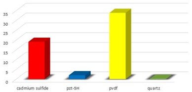
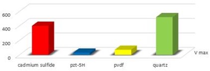
Fig. 6 shows a plot of comparison among the four RMS absolute values of electric potential developed by the different piezoelectric materials in the situation described above, while the histograms of Fig. 7 show also the minimum and the maximum absolute value of electric potential.
Even if the minimum and maximum value developed of electric potential derives from CdS and Quartz respectively, the comparison of RMS values leads to individuate as the best compromise the polymeric material PVDF for the proposed situation. This is due to the flexibility of this material that induces the cantilever beam to a greater deformation than those realized with the other materials: this implies a higher developed voltage.
Fig. 6Comparison of RMS values of electric potential developed with different piezoelectric materials
Fig. 7Comparison of electric potential developed with different piezoelectric materials
a) RMS (mV)
b) (mV)
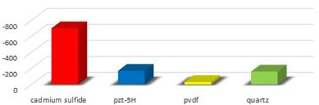
c) (mV)
4. Conclusions
In this paper, a study to model and simulate a piezoelectric cantilever beam subjected to wind pressure was described. The study was lead comparing the behavior of a cantilever beam, made of silver and PVDF and subjected to wind force, observed with an experimental apparatus, with that of a FEM model of a device with the same features. The behavior of cantilever was modeled using constitutive equations of piezoelectric materials and mechanical equilibrium equations. The comparison of values of electrical potential developed, because of deformations of beam caused by wind allowed the validation of the simulated device with its geometry, boundaries conditions, constraints and pressure applied. Other simulations were done with different piezoelectric materials to find the best one that allows the cantilever to provide the best values of electrical potential under wind stress, in the fixed analyzed configuration. Comparison leads to individuate as best compromise the polymeric material because of the best RMS value of potential and the less expensive cost.
Ongoing research will investigate a more complex model including laminar flow to simulate wind flow acting on cantilever. Finally, an appropriate electric circuit to store and reuse energy developed by the device described in this paper is going to be realized.
References
-
Anton S. R., Sodano H. A. A review of power harvesting using piezoelectric materials (2003-2006). Smart Materials and Structures, Vol. 16, Issue 3, 2007, p. 1-21.
-
Heung Soo K., Joo-Hyon, Jaehwan K. A review of piezoelectric energy harvesting based on vibration. International Journal of Precision Engineering and Manufacturing, Vol. 12, Issue 6, 2011, p. 1129-1141.
-
Sirohi J., Mahadik R. R. Harvesting wind energy using a galloping piezoelectric beam. Journal of Vibration and Acoustics, ASME, Vol. 134, Issue 1, 2011, p. 1-8.
-
Yang Y., Shen Q. L., Jin J. M., Wang Y. P., Qian W. J., Yuan D. W. Rotational piezoelectric wind energy harvesting using impact-induced resonance. Applied Physics Letters. Vol. 105, Issue 5, 2014.
-
Cook-Chennault K. A., Thambi N. Sastry Powering MEMS portable devices – a review of non-regenerative and regenerative power supply systems with special emphasis on piezoelectric energy harvesting systems. Smart Materials and Structures. Vol. 17, Issue 4, 2008, p. 1-33.
-
Erturk A., Inman D. J. Piezoelectric Energy Harvesting. John Wiley and Sons, Ltd., Chichester, UK, 2011.
-
Kluger J. M., Moon F. C., Rand R. H. Shape optimization of blunt body vibro-wind galloping oscillator. Journal of Fluids and Structures, Vol. 40, 2013, p. 185-200.
-
Rezaei N., Tabesh A., Dehghani R., Aghili A. An efficient piezoelectric windmill topology for energy harvesting from low speed air flows. IEEE Transactions on Industrial Electronics, Vol. 62, Issue 6, 2015, p. 3576-3583.
-
An American National Standard. IEEE Standard on Piezoelectricity. ANSI/IEEE Std 176, The Institute of Electrical and Electronics Engineers Inc., New York, USA, 1988.
-
Roh Y., Varadan V. V., Varadan V. K. Characterization of all the elastic, dielectric and piezoelectric constants of uniaxially oriented poled PVDF films. IEEE Transactions on Ultrasonics, Ferroelectrics, and Frequency Control, Vol. 49, Issue 6, 2002, p. 836-847.
-
http://www.meas-spec.com/.
-
Clapp A. L. National Electrical Safety Code. IEEE Standard Information Network, 1972.
Cited by
About this article

