Abstract
The researches of wind energy harvesting have been more and more popular in recent years. In the paper, a vibration energy caused by a breeze is harvested with a cantilevered beam using a piezoelectric patch. When a swaging fan applies a breeze environment, the alternating voltage generates from the piezoelectric patch. Moreover, by designing a full wave rectifier, the alternating voltage from the piezoelectric patch is transformed as a DC voltage. Through some experiments, the amplitude of the alternating voltage is about 2.70 V and its frequency is 2.60 Hz (the first natural frequency of the cantilevered beam). And the gained DC voltage is about 2.45 V and can be made a luminous diode be on. These experimental results indicate that vibration energy caused by the breeze can be harvested with a full wave rectifier.
Highlights
- Vibration energy caused by a breeze is harvested with a cantilevered beam with a piezoelectric patch
- An alternation voltage (its amplitude 2.7V) generated from the piezoelectric patch is transformed as a DC voltage (2.45V)
- The DC voltage can make a white diode be light
1. Introduction
With modern electronic technology’s faster and faster development, the circuit system has become more to miniaturization and integration [1]. That can promote the micro-electro- mechanical system application (for example, micro sensor, MEMS contact lenses, capsule endoscopy, intelligent terminal) in various fields (such as medical, military and consumer electronic and so on) toward the light, thin, short and small characteristics of the development. Now, the traditional power supply of these MEMS equipment is polymer battery [2]. The traditional power supply mode has the characteristics of short life time, high cost, and even cause great pollution to the surrounding environment. It will further affect more widely application of the MEMS in various fields. Therefore, looking for new supply energy will be very meaningful [3].
In recent years, various forms of energy collection, including solar energy, mechanical energy, and fluid kinetic energy and so on, have attracted more and more attention from researchers at home and abroad [4-6]. However, wind energy is a kind of clean and renewable energy and is widely existed in the surrounding environment, especially the low-speed breeze. Large wind turbine not only has complex structure, but also has low feasibility and efficiency under long working conditions [7]. Therefore, the fluid kinetic energy collection of low-speed breeze is easier to realize than the energy conversion of large rotating wind turbines. Micro-wind energy collection application is to supply power to micro-small self-powered energy system [8]. By combining wind-induced vibration structure and smart material to form a wind energy collector, the collector can convert fluid kinetic energy into mechanical energy and then into electrical energy [9]. Compared with rotational structures, the study of wind induced vibration energy collection is the main trend [10].
The rest of this paper is organized as follows. The cantilevered beam is introduced in Section 2. Some experimental results and discussion are displayed in Section 3. Finally, conclusions are presented in Section 4.
2. The cantilevered beam with a piezoelectric patch
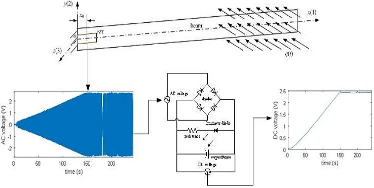
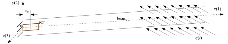
Fig. 1 shows a cantilevered aluminum beam with a piezoelectric sensing patch under a wind environment. is the distance from the fixed end of beam to the piezoelectric patch. The piezoelectric patch is served as an energy converter. When the wind is coming and the wind force acts on the beam, the cantilevered beam wags its free end of the beam. Then, a strain generates in the root end of the beam with the wagging movement. Furthermore, a voltage generates across the piezoelectric patch with the root strain of the smart beam. Therefore, the generated voltage from the piezoelectric patch is observed and explored with some tests in the paper.
Fig. 1Cantilevered beam with a piezoelectric sensing patch under a wind environment
Because the beam is a cantilevered structure, the bending displacement along the direction is expressed as:
where is a vibration mode function, is the generalized coordinates.
The converting energy principle is written with an equation set as [11]:
where , and are the density and the across area respectively of the beam, is the length of beam, and are damping coefficient and natural frequency respectively, is the electromechanical coupling, is the effective capacitance of the piezoelectric sensing layers, and is a load’s resistance.
Table 1Corresponding parameters
Beam | Piezoelectric |
0.4770 m, 21.35×10⁻⁶, 2.77×10³ kg/m3, ×2.6 rad | 2.0 cm, –1.7×10⁻¹⁰ C/N, 420 Ω, 25.7 nF |
3. Experimental results and discussions
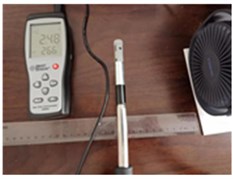
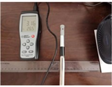
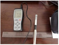
The experimental setup of the breeze energy harvesting validation is shown in Fig. 2. The breeze environment is supplied with a small fan. And the fan has three gears of wind speed (2.48 m/s, 3.16 m/s and 4.10 m/s). The wind speed is measured with a anemometer with a distance about 10 cm from the fan in Fig. 3, and the wind speed of the breeze is 3.4 m/s-5.4 m/s. Moreover, the fan has an alternating rotational movement round the axis. The rotational alternating frequency is equal to about the first order natural frequency of beam. Therefore, the third gear of the fan will offer an alternating breeze wind environment.
Fig. 2Experimental setup
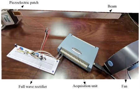
Fig. 3Measuring wind speed
a) First gear
b) Second gear
c) Third gear
Fig. 4Circuit diagram of full wave rectifier
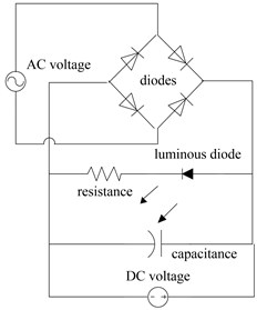
When an alternating breeze wind force is applied on the free end of the beam, resonance will occur for the smart beam. The amplitude of the swaging movement for the smart beam is larger, and then the voltage generated from the piezoelectric patch will be larger. Furthermore, the generated voltage from the piezoelectric patch is an alternating signal. Using a full wave rectifier in Fig. 4, the alternating voltage is transferred a DC voltage. To gain the output DC voltage, a data acquisition unit is using collect the output DC voltage and the collected voltage data is saved with LABVIEW Software in computer, as shown in Fig. 2.
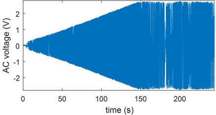
Fig. 5 shows the alternating voltage from the piezoelectric patch when a breeze acts on the free end of the cantilevered beam. Moreover the amplitude of the alternating voltage is about 2.70 V and its frequency is equal to the first natural frequency (about 2.60 Hz) of the cantilevered beam. When the alternating voltage is processed by the full wave rectifier in Fig. 4, the output voltage of the rectifier is a DC voltage. By the DC voltage, the white luminous diode is flashing compared with the unlit diode in Fig. 6(a), and then the output DC voltage (about 2.45 V) is shown in Fig. 6(b).
Fig. 5AC voltage from piezoelectric patch
Through an experimental setup, an alternating voltage generated from a piezoelectric patch is collected with the vibration of the cantilevered beam when an alternating breeze acts on the free end of the smart beam. By a full wave rectifier, the alternating voltage is transferred as a DC voltage. The DC voltage is about 2.45 V and makes a white luminous diode be on.
Fig. 6Output DC voltage under a breeze environment
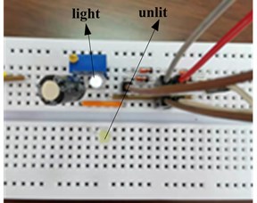
a) White luminous diode
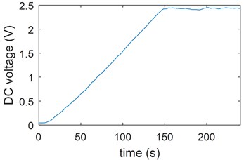
b) Output DC voltage
4. Conclusions
In the paper, a vibration will generates when a breeze acts on the free end of the cantilevered beam. Moreover, the root strain of the beam is the largest by the vibration of beam caused when the alternating frequency of the breeze is near the first natural frequency of the cantilevered beam. Then, there is an alternating voltage in the piezoelectric patch with its piezoelectric property. Through the principle, a full wave rectifier is designed to transfer the alternating voltage (its amplitude is 2.70 V and its frequency is about 2.60 Hz) in the piezoelectric patch into a DC voltage. Through experimental results, the DC voltage (about 2.45 V) can make a white luminous diode be on.
References
-
He Ming, Wang Sheng, Zhong Xiang, et al. Study of a piezoelectric energy harvesting floor structure with force amplification mechanism. Energies, Vol. 12, Issue 18, 2019, p. 3516.
-
Grzybek Dariusz, Micek Piotr Piezoelectric energy harvesting based on macro fiber composite from a rotating shaft. Physica Scripta, Vol. 94, Issue 9, 2019, p. 095802.
-
Stanton Samuel C., Mcgehee Clark C., Mann Brian P. Nonlinear dynamics for broadband energy harvesting: Investigation of a bistable piezoelectric inertial generator. Physica D-Nonlinear Phenomena, Vol. 239, Issue 10, 2010, p. 640-653.
-
Kim Heung Soo, Kim Joo Hyong, Kim Jaehwan A Review of piezoelectric energy harvesting based on vibration. International Journal of Precision Engineering and Manufacturing, Vol. 12, Issue 6, 2011, p. 1129-1141.
-
Liu Huicong, Tay Cho Jui, Quan Chenggen, et al. Piezoelectric MEMS energy harvester for low-frequency vibrations with wideband operation range and steadily increased output power. Journal of Microelectromechanical Systems, Vol. 20, Issue 5, 2011, p. 1131-1142.
-
Jung Seok-Min, Yun Kwang-Seok Energy-harvesting device with mechanical frequency-up conversion mechanism for increased power efficiency and wideband operation. Applied Physics Letters, Vol. 96, Issue 11, 2010, p. 111906.
-
Kim Sang-Gook, Priya Shashank, Kanno Isaku Piezoelectric MEMS for energy harvesting. MRS Bulletin, Vol. 37, Issue 11, 2012, p. 1039-1050.
-
Cao Dongxing, Gao Yanhui, Hu Wenhua Modeling and power performance improvement of a piezoelectric energy harvester for low-frequency vibration environments. Acta Mechanica Sinica, Vol. 35, Issue 4, 2019, p. 894-911.
-
Li Xiangyang, Upadrashta Deepesh, Yu Kaiping et al. Analytical modeling and validation of multi-mode piezoelectric energy harvester. Mechanical Systems and Signal Procession, Vol. 124, 2019, p. 613-631.
-
Iqbal Muhammad, Khan Farid Ullah Hybrid vibration and wind energy harvesting using combined piezoelectric and electromagnetic conversion for bridge health monitoring applications. Energy Conversion and Management, Vol. 172, 2018, p. 611-618.
-
Ramalingam Usharani, Gandhi Uma, Mangalanathan Umapathy, et al. A new piezoelectric energy harvester using two beams with tapered cavity for high power and wide broadband. International Journal of Mechanical Sciences, Vol. 142, 2018, p. 224-234.
About this article

This work was supported by the Shanghai Innovation Training Project for College Students (cs1901002) and the National Natural Science Foundation of China (11702168).
