Abstract
Aiming at improving vibration performance of 1.5 MW wind turbine blades, the theoretical model and the calculation process of vibration problems under geometric nonlinearity and unidirectional fluid-structure interaction (UFSI) were presented. The dynamic stability analysis on a 1.5 MW wind turbine blade was carried out. Both the maximum brandish displacement and the maximum Mises stress increase nonlinearly with the increase of wind speed. The influences of turbulent effect, wind shear effect and their joint effect on displacement and stress increase sequentially. Furthermore, the stability critical curves are calculated and analyzed. As a result, the stability region is established where the wind turbine blade can run safely.
1. Introduction
In recent years, wind turbine is developing towards single high power and large scale, which makes the blade design confront with numerous new theories and technical problems. The sea wind field becomes very complicated under the influence of wind shear and turbulence, which can easily cause vibration damage and dynamic instability of wind turbine blades [1, 2]. Therefore, it is particularly important to avoid the stability destruction problem of the blades under the actual working conditions.
In the aspects of turbulent effect (TE), wind shear effect (WSE) and stability, some researches have been conducted with a focus on individual one of above three issues. Huang et al. [3] analyzed the dynamic response of wind power tower under the storm load, and the results show that the horizontal displacement at the top of wind power tower is greater than allowable deformation at fluctuating wind situation. Han et al. [4] carried out a numerical simulation on 3D steady flow around a 1.3 MW wind turbine at different wind speeds under wind shear condition, and it was found that the non-uniformity from the speed variation at different vertical height should not be ignored with increasing diameter of wind turbine rotors. Abdel-Magid et al. [5] studied the dynamic stability of a single wind-turbine generator under widely varying loading conditions. Eggleston et al. [6] analyzed aerodynamic stability of an elastic blade by the finite element method. Riziotis et al. [7] introduced some application examples of stability calculation methods for variable pitch and stall-regulated wind turbines. Larsen et al. [8] established the brandish shimmy torsion coupling model of a blade by finite element method to study the internal resonance of brandish shimmy, and parameters stability and stochastic stability under the general situation. Thomsen et al. [9] discussed the brandish shimmy stability of a blade by utilizing the blade central articulated model. Zhao et al. [10] conducted modal and stability analysis of a wind turbine blade by ANSYS software, obtained the first 10 order frequencies, and analyzed the blade stability under the ultimate load. Chaviaropoulos et al. [11, 12] studied the blade stability problem of the brandish-shimmy flutter induced by stall using the eigenvalue method of the frequency domain. Kwon et al. [13] investigated the effects of rotating speed, tilt angle, and pitch angle on dynamic stability characteristics of a wind turbine blade. Jeong et al. [14] investigated the effects of torsional stiffness on the dynamic stability of a wind turbine blade under fluid-structure interaction.
As it has been shown above, TE and WSE have a certain influence on the vibration of the blade structure, and the blade stability researches have been mainly confined to eigenvalue method to solve static stability problem and to the characteristic value method in frequency domain to study flutter stability problem of the blades. Therefore, in order more realistically to reveal dynamic instability phenomena of the wind turbine blades, it is necessary to consider the influence of both TE and WSE on the geometrically non-linear blade structure.
In this work, the stability region in relation to material properties, wind speed, TE and WSE is explored under complicated offshore wind working conditions to meet the instability criterion of blades. The quantitative relationships among the maximum brandish displacement, the maximum Mises stress, elastic modulus and the wind speed are determined where the instability of the wind turbine blades occurs. The results provide the technical guidance for the safe and reliable operation of the blades.
2. Theoretical model
2.1. Physical model
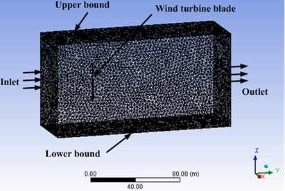
For the uni-direction fluid-structure interaction (UFSI), the force on the fluid-structure interface, which is applied to the structure to cause its deformation, is got by the calculation on fluid field. Fluid-structure interaction model of three dimensional flow fields is displayed in Fig. 1.
2.2. Control and discrete equations in fluid domain
The basic conservation laws of fluid domain include the mass conservation law, the momentum conservation law and the energy conservation law. In order to analyze these equations easily and solve them by using the same program, the general form of governing equations is established. is the general variable, which indicates the direction of velocity component , , , and it can be expressed as [15]:
where, , , respectively are the air density, the generalized diffusion coefficient and the generalized source term. For the continuity equation, 1; for the momentum equation, , where and are the velocity component in each direction; for the two-equation - turbulence model, . The indicator values of , are 1, 2 and 3 respectively, and , are ascertained according to .
Fig. 1The meshing and interaction diagram of fluid-structure field
The control equation uses finite volume discretization according to the computational grid. Integral operation is conducted on the control volume and time frame , and Guass divergence theorem is introduced. The general form of the discrete equations is as follows [15]:
in which is the adjacent node, ; is the coefficient; comes from source item.
2.3. Wind load calculation
2.3.1. Wind shear determination
The influence of WSE on the blade becomes larger and larger with increasing diameter of the wind turbine rotor. Generally, an exponential model is employed to describe the wind speed under the WSE [16-18]:
where is the wind speed at which is vertical height from the ground; is average wind speed of standard reference height which is 10 m in Chinese Standard; is the wind shear index which is selected as 0.12 by experience because the geomorphologic situation of the blade is similar to the offshore region [19].
2.3.2. Turbulence determination
First of all, fluctuating wind spectrum needs to be simulated under the certain condition to consider the influence of TE on wind turbine blades. Davenport spectrum is the average value of 90 times vertical turbulent power spectrum based on different locations, different heights around the world, and the expressions are given as [20]:
where and are power spectrum and circle frequency of the fluctuating wind, respectively; is the ground roughness coefficient. According to the theory of random vibration and Chinese load specification, the formula of can be written as:
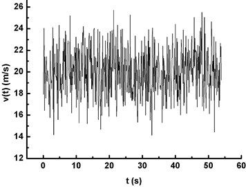
The frequency domain was converted into the time domain by the self-programmed program based on the harmonic synthesis method and Eq. (4), and the time domain curve of the fluctuating wind speed was obtained. When 20 m/s and 0.36587 Hz are selected, the variation relationship of fluctuating wind velocity with time is simulated and shown in Fig. 2.
Fig. 2Time history of fluctuating wind velocity
In the case of average wind velocity (AWV), TE and WSE, Eq. (2) is solved by iterative method. Velocity field satisfying the continuity equation is obtained, and so wind pressure distribution on the blade surface is calculated.
2.4. Nonlinear dynamics equation and discrete equation in structure domain
The blade meets the geometrically nonlinear equation [21]:
where is stress tensor, is the blade displacement vector, is the blade material density and is the body force vector. The constitutive equation and the relationship between displacement and strain for the geometrically nonlinear elastic body are respectively written as:
in which , are shear modulus of elasticity and LAME coefficient respectively, and is the unit tensor.
In general case, the discrete motion differential equation of geometrically nonlinear structure domain is:
where , are mass matrix and damping matrix, respectively; ; is the wind load column vector at ; is the nonlinear term of equation, it can be expressed as:
where is the tangential stiffness matrix calculated by node displacement at .
For the discrete motion differential Eq. (10), the displacement, velocity and acceleration at are calculated by Newmark method and Newton-Raphson iterative method [22].
2.5. Modal analysis
When the natural frequency of the blade structure is solved, the classical eigenvalue equation is expressed as [23]:
where and ( 1, 2, 3,…) are the feature vector and the natural frequency of the th order modal.
3. Entity modeling and finite element analysis of wind turbine blade
3.1. Entity modeling and parameter setting
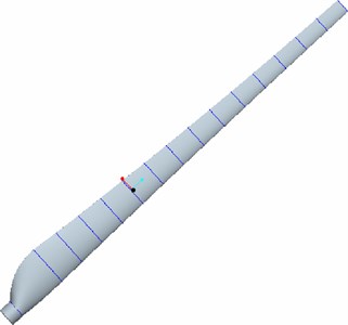
The correct establishment of entity model directly affects the accuracy and reliability of numerical results in the process of the finite element analysis by using ANSYS software. The design parameters of 1.5 MW wind turbine chosen in this paper are shown in Table 1. The blade entity model set up by the Pro/E software is listed in Fig. 3.
Table 1Main parameters of the wind rotor
Diameter | Blade number | Rated wind speed | Rated revolution | Cut-out wind speed | Blade section |
86 m | 3 | 7.93 m/s | 14.4 rpm | 25 m/s | NACA44 |
Nowadays, the glass-fiber reinforced plastics (GRPs) are commonly used to manufacture the commercial wind turbine blade, because of their light weight, high strength and good rigidity. Specific material parameters are shown in Table 2 [24].
Table 2Material parameters of GRP for the wind blade
Elasticity modulus (GPa) | Poisson’s ratio | Shear modulus (GPa) | Density (g/cm3) |
17.6 | 0.17 | 2.08 | 1.70 |
Fig. 3The entity model of the 1.5 MW wind blade
3.2. Finite element mesh
Model meshing, which directly affects the accuracy of the subsequent numerical results, is the basis for differential equation discretization and numerical solution. The overall grid of fluid-structure field is shown in Fig. 1.
With the increase of the unit grid quantity, it is found that the maximum brandish displacement of the blade is convergent, as shown in Table 3. On the premise of achieving both the calculation precision and the speed, the grid quantities of fluid-structure domain are determined to be 430847 and 9656, respectively.
Table 3Grid independent verification of the fluid-structure domain
Region | Grid unit number | Maximum displacement (m) | Relative error (%) |
Structure field | 9656 | 1.109 | – |
12320 | 1.105 | 0.36 | |
16020 | 1.103 | 0.18 | |
Fluid field | 430847 | 1.109 | – |
454282 | 1.107 | 0.18 | |
483263 | 1.108 | 0.09 |
4. Numerical results and discussion
4.1. Model validation
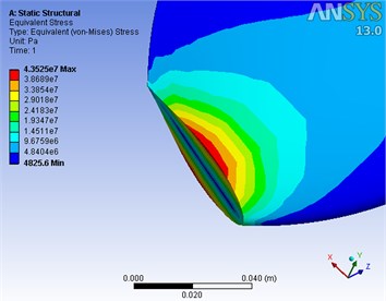
The numerical program is degenerated into the cantilever blade structure corresponding to the reference [25] in which the maximum Mises stress of blade root portion is 42.70 MPa, while the one calculated in this work is 43.53 MPa as shown in Fig. 4. The relative error is only 1.94 %, which verifies the reliability of the present theoretical method, the entity modeling and finite element method.
4.2. The natural frequencies of wind turbine blade
The actual percentage contribution of each order mode calculated by modal analysis is different from the system brandish vibration, and the brandish vibration mode is mainly concentrated in the first six modes. The first six natural frequencies are listed in Table 4.
Table 4The first six natural frequencies of the wind turbine blade
Mode number | 1 | 2 | 3 | 4 | 5 | 6 |
Frequency (Hz) | 0.36587 | 1.1409 | 1.8303 | 2.4671 | 4.3673 | 5.3353 |
Fig. 4Maximum Mises stress contour
4.3. Blade vibration analysis under periodic wind speed
The dynamic stability of the wind turbine blade under the action of fluid structure interaction is emphatically discussed in this work. The stability region is determined by calculating the critical curves of dynamic instability, and the characteristic of instability is the vibration divergence. Therefore, the frequency of the periodic wind speed is set close to the first-order natural frequency of the blade, and the dynamic stability analysis is carried out with UFSI taken into account. AWV effect (0.36587 Hz), TE (0.36587 Hz) and WSE & TE (0.36587 Hz) are respectively denoted by Condition I, Condition II and Condition III. The vibration divergence curves of maximum displacement and Mises stress are obtained under above three conditions, as shown in Fig. 5.
Fig. 5 depicts the vibration divergence curves of maximum displacement and Mises stress under three conditions with UFSI considered, and it is clear that:
1) The peak of maximum displacement gradually increases with time and the vibration divergence phenomenon appears under each condition, as shown in Fig. 5(a), (c) and (e).
2) The maximum Mises stress of the blade also increases with time and divergence phenomenon becomes visible (see Fig. 5(b), (d) and (f)).
3) The peak value of the displacement and the Mises stress under Condition III is the largest, which indicates that WSE & TE has the significant impact on the wind turbine blade. Therefore, WSE & TE should not be ignored in the process of numerical simulation, otherwise simulation result will deviate from the real one.
When the vibration divergence of the blade occurs, the relationship among the maximum displacement, the maximum Mises stress and wind speed () in the specified computation period under three conditions is shown in Fig. 6 and Fig. 7. It can be seen that:
1) Both the maximum displacement and the Mises stress increase with the increase of wind speed under three conditions and the curve under each condition shows nonlinear upward trend. The value difference between two neighbouring curves also increases, which means that wind speed has significant influences on the blade stability.
2) The displacement and the stress under Condition III show a maximum, and the variation gradient also keep the maximum changing with wind speed, which implies that the TE & WSE has an obvious effect on the stability of the blade.
3) At the same wind speed, the difference in either displacement or stress between Condition II and Condition III represents the contribution from WSE, and the one under Condition I and Condition II from TE. It is obvious that the influence of WSE on displacement and stress is greater than that of TE, and this trend becomes more and more significant with the increase of wind speed.
4.4. Search of blade instability region
In order for the wind turbine to operate safely under actual working condition, it is necessary to ensure that the maximum displacement does not exceed the horizontal distance between the blade and tower. In this study, two horizontal distances of 1.5 m and 1.0 m are chosen as the maximum allowable displacement of the blade to meet the safe design requirements. When the dynamic instability phenomenon takes place, the quantitative relationship between Mises stress and elasticity modulus of blade under three different conditions is determined according to the safe horizontal distance criterion. This relationship provides the safety reference for the materials selection of wind turbine blades.
Fig. 5The divergent response curves of the blade under three different conditions
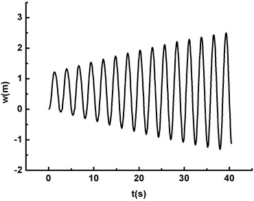
a) The maximum displacement under Condition I (20m/s, )
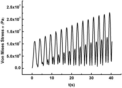
b) The maximum Mises stress under Condition I (20 m/s, )
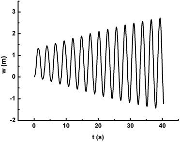
c) The maximum displacement under Condition II (20 m/s, )
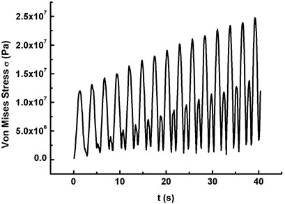
d) The maximum Mises stress under Condition II (20 m/s, )
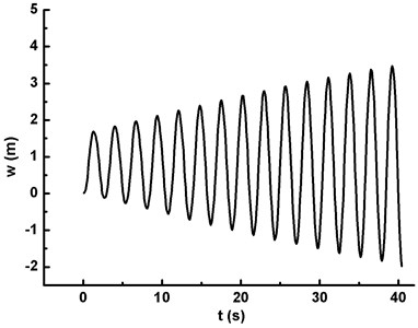
e) The maximum displacement under Condition III (20 m/s, )
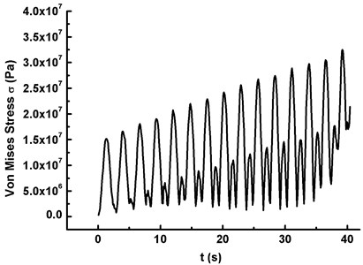
f) The maximum Mises stress under Condition III (20 m/s, )
Fig. 6The maximum displacement versus wind speed under three conditions
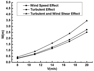
Fig. 7The maximum Mises stress versus wind speed under three conditions
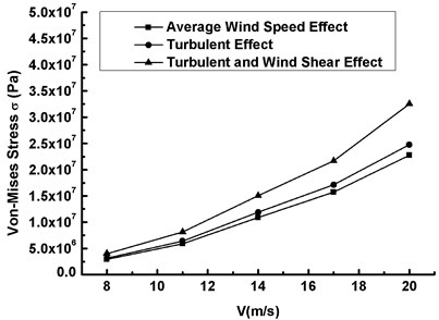
Fig. 8The maximum Mises stress versus elasticity modulus under AWV (V-= 20 m/s, ω=ω1)
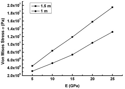
Fig. 9The maximum Mises stress versus elasticity modulus under TE (V-10= 20 m/s, ω0=ω1)
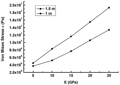
Fig. 10The maximum Mises stress versus elasticity modulus under TE & WSE (V-10= 20 m/s, ω0=ω1)
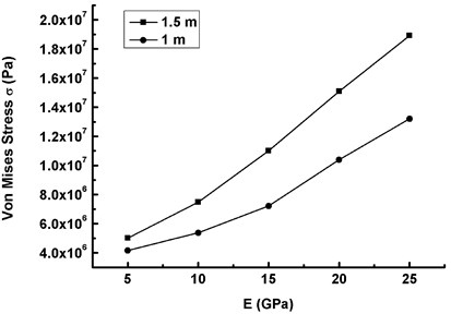
When the vibration diverges, Figs. 8, 9 and 10 represent the critical curves of the maximum Mises stress of the blade versus elastic modulus at two safe horizontal distances 1.5 m and 1.0 m. It can be drawn that:
1) Both two curves under three working conditions are the critical dynamic stability curves which determine whether the wind turbine blade can operate safely. When the maximum Mises stress calculated by material elastic modulus at each condition stays above the critical curve, the elastic dynamic instability happens and the blade cannot operate safely. Otherwise, the dynamic response of the blade is stable.
2) The critical curves under three working conditions have the nonlinear trend with the increase of the elasticity modulus at 1.0 m safe horizontal distance, and the maximum Mises stress is between 3.16 MPa to 13.40 MPa.
3) At 1.5 m safe horizontal distance, the critical curves under three working conditions basically present a linear upward trend with the increase of the elasticity modulus, and the gradient of the critical curve of the maximum Mises stress decreases slightly from Condition I to Condition III.
5. Conclusions
The dynamic stability calculation of the blade is conducted under UFSI. Both the divergence of the response curve and the maximum allowable displacement between the blade and tower are regarded as the instability criterion. The influence law of the coming wind speed and the material elastic modulus on the dynamic stability of the blade under different working conditions is found, and the critical curves between the maximum Mises stress and the elastic modulus are established. Conclusions are drawn as follows:
1) The first six natural frequencies of wind turbine blade are obtained by the modal analysis. The response curves of displacement and stress show a divergent trend when the wind speed frequency is close to the first natural frequency of the blade structure, which means that the dynamic instability occurs.
2) Under the dynamic instability of the blade, the quantitative relationship among displacement, Mises stress and wind speed is obtained, and it is also found that the contribution of WSE to displacement and stress is more than that of TE.
3) According to the stability criterion that vibration does not diverge and the maximum displacement does not exceed horizontal distance between the blades and tower, the dynamic stability region of the blade is calculated at two safe horizontal distances, i.e. 1.0 m and 1.5 m, respectively.
4) On the basis of the results in this study, it’s easier and wiser to select the suitable blade material. At the same time, the blind design of the technical personnel can be avoided in the design stage, and the selection of material parameters is optimized.
References
-
Herbert Joselin G. M., Iniyan S., Sreeyalsan E., Rajapandian S. A review of wind energy technologies. Renewable and Sustainable Energy Reviews, Vol. 11, Issue 6, 2007, p. 1117-1145.
-
Philippidis T. P., Vionis P. S. Composite rotor blade model verification by means of full-scale static and model testing. Proceedings of EUWEC, 1996, p. 946-949.
-
Huang S., Song B., He S., Wei W. Numerical analysis of dynamic response and in-site monitoring of wind power tower considering the influence of the fluctuating wind load. China Civil Engineering Journal, Vol. 45, 2012, p. 102-106.
-
Han Z. H., Li Y., Ji J. Numerical study on 3D steady flow of a 1.3 MW wind turbine considering wind shear factor. Journal of Chinese Society of Power Engineering, Vol. 31, Issue 10, 2011, p. 779-783.
-
Abdel-Magid Y. L., El-Amin I. M. Dynamic stability of wind-turbine generators under widely varying loading conditions. International Journal of Electrical Power and Energy Systems, Vol. 9, Issue 3, 1987, p. 180-188.
-
Eggleston D. M., Stoddard F. Wind turbine engineering design. Structural Dynamic, Vol. 7, 1987, p. 35-59.
-
Riziotis V. A., Voutsinas S. G. Aeroelastic Stability of wind turbines the problem, the methods and the issues. Wind Energy, Vol. 7, 2004, p. 373-392.
-
Larsen J. W., Iwankiewicz R., Nielsen S. R. K. Nonlinear stochastic stability analysis of wind turbine wings by Monte Carlo simulations. Probabilistic Engineering Mechanics, Vol. 22, 2007, p. 181-193.
-
Thomsen K., Petersen J. T. A method for determination of damping for edgewise blade vibrations. Wind Energy, Vol. 3, 2000, p. 233-246.
-
Zhao N., Li X. J., Li C. L. Model analysis and stability analysis of wind turbine blades based on Ansys modeling. Fiber Reinforced Plastics/Composites, Vol. 6, 2010, p. 14-17.
-
Chaviaropoulos P. K. Flap/lead-lag aerolastic stability of wind turbine blade sections. Wind Energy, Vol. 2, 1999, p. 99-112.
-
Chaviaropoulos P. K., Soerensen N. N., Hansen M. O. L. Viscous and aerolastic effects on wind turbine blades, the VISCEL project, part II: aerolastic stability investigations. Wind Energy, Vol. 6, 2003, p. 387-403.
-
Kwon S., Chung J., Yoo H. H. Structural dynamic modeling and stability of a rotating blade under gravitational force. Journal of Sound and Vibration, Vol. 332, Issue 11, 2013, p. 2688-2700.
-
Jeong M. S., Lee I., Yoo S. J., Park K. C. Torsional stiffness effects on the dynamic stability of a horizontal axis wind turbine blade. Energies, Vol. 6, Issue 4, 2013, p. 2242-2261.
-
Zhang J. P., Pan L. L., Hu D. M., Zhuang J. X. Influence of offshore average wind speeds on dynamic responses of the wind turbine blade. East China Electric Power, Vol. 39, Issue 4, 2011, p. 636-639.
-
Dale S. L. D., Lehn P. W. Simulation model of wind turbine 3p torque oscillations due to wind shear and tower shadow. IEEE Transactions on Energy Conversion, Vol. 21, Issue 3, 2006, p. 717-724.
-
Xiong L. J. Wind Power New Technology and Power Generation Engineering Design, Operation, Maintenance and Standard Specification of Practical Manual. China Science and Technology Culture Press, Beijing, China, 2005.
-
Spera D. A. Wind Turbine Technology. ASME Press, New York, US, 1994.
-
Building Structures Specification GB50009-2001. Chinese National Standards (CNS), Building Industry Press, Beijing, China, 2002.
-
Davenport A. G. The spectrum of horizontal gustiness near the ground in high winds. Royal Meteoral, Vol. 87, 1961, p. 194-211.
-
Bai X. Z. Magnetoelasticity, thermal magnetoelasticity and their applications. Advances in Mechanics, Vol. 26, Issue 3, 1996, p. 390-406.
-
Zhang J. P., Li Z. N. Dynamic instability of magnetoelastic coupling interactions of cantilever conductive thin plates. Journal of Zhejiang University (Engineering Science), Vol. 40, Issue 3, 2006, p. 414-418.
-
Gao Q. Z., Zhang D. L., Sun Q. Modal analysis of planet gear for cutting unit of road header based on Pro/E and ANSYS. Mechanical Research and Application, Vol. 1, Issue 26, 2013, p. 15-17.
-
Zong N. N. Design and FE Analysis of the Blade for Small Horizontal Axis Wind Turbine. Master Thesis, Shanghai Jiaotong University, Shanghai, 2009.
-
Cao R. J., Liu D. X. Experimental investigation on static structural characteristics of a horizontal axis wind turbine. Acta Energiae Solaris Sinica, Vol. 22, Issue 4, 2001, p. 436-439.
About this article

This work was supported by various research funds including National Natural Science Foundation of China (11572187); Innovation Program of Shanghai Municipal Education Commission (14ZZ154); Foundation of Science and Technology Commission of Shanghai Municipality (14DZ2261000, 13160501000).
Jianping Zhang and Wenlong Chen built the theoretical model. Tingjun Zhou performed the numerical simulation and relevant analysis. Jianping Zhang and Tingjun Zhou wrote the paper. Helen Wu, Danmei Hu and Jianxing Ren reviewed and edited the manuscript. All authors read and approved the manuscript.
