Abstract
An experiment was performed in a deep-water basin to investigate VIV mechanisms under shear flow. Lift force, drag force, and tension response were obtained. Results show that multiple frequencies are appeared for nonuniform vortex shedding frequency and interaction between the IL and CF vibrations. Beat phenomenon is observed in time history of lift force, and decreased with the increasing riser pretension. Dominant frequencies of riser tension are consistent with the IL and CF dominant frequency, and amplitudes of the tension are not uniform. VIV is inhibited with increasing riser pretension and the dominant frequencies also increase with increasing riser tension.
1. Introduction
When current flows across marine risers, a vortex forms on both sides of these risers. The vortex shed on the riser may induce forces, which include lift and drag forces. Vortex-induced lift force is in the cross-flow (CF) direction, whereas vortex-induced drag force is in the in-line (IL) direction. Under the effect of lift and drag forces, the riser vibrates in both the CF and IL directions, which is called vortex-induced vibration (VIV). When the vortex shedding frequency approaches the natural frequency of the risers, the lock-in phenomenon occurs. Under this condition, the vibration is significant and has a potentially destructive effect on risers.
Several studies have focused on VIV under uniform flow over the past several decades [1-13]. Despite the large number of studies on VIV under uniform flow, we should note that current is not uniform, but sheared, under real marine conditions. Therefore, investigating the VIV mechanism under the influence of shear flow is necessary.
Kiya et al. [14] investigated vortex shedding from a circular cylinder in a uniform shear flow with the Reynolds number ranging from 35 to 1500. They found that the critical Reynolds number when the VIV occurred was higher than that in a uniform stream. Kwon et al. [15] showed that the drag coefficient decreased with increasing Reynolds number, whereas the Strouhal number increased with increasing shear parameter in laboratory experiments. Balasubramanian and Skop [16] used an elastically coupled Van der Pol oscillator to investigate vortex shedding in shear flow. Vandiver et al. [2, 17] indicated that lock-in might occur under highly sheared conditions through experiments. Kurose and Komori [18] investigated drag and lift forces on a rotating sphere in a linear shear flow with a Reynolds number of 1 to 500 by using a numerical method. Lei et al. [19] showed that the Strouhal number and drag coefficient decreased with increasing shear parameter. Kang [20] investigated the circular cylinder under the effect of uniform shear flow at low Reynolds numbers and found that drag force and shedding frequency remained constant or slightly decreased as shear rate increased. Sumner and Akosile [21] showed that the Strouhal number and mean base pressure coefficient increased, whereas the mean drag force coefficient decreased because of the influence of the low to moderate shear of the experimental method. Marcollo and Hinwood [22] used a new experimental setup and found that an in-line VIV can occur at low Ur in shear flow. Lie and Kaasen [23] performed large-scale model testing in linearly sheared flow at Hanøytangen outside Bergen. They found that the riser response was irregular and that the increasing flow speed likewise increased the degree of irregularity. Huang et al. [24] investigated the VIV in shear flow through the numerical simulation of a vertical riser. They compared their results with previously published experimental data. Despite these works, experimental studies on VIV of the marine riser under shear flow remain limited.
This study aims to investigate lift force, drag force, and tension response in vortex-induced vibration for marine risers under shear flow. In order to investigate VIV mechanisms more thoroughly, we carried out the experiment in a deep-water offshore basin in State Key Laboratory of Ocean Engineering in Shanghai Jiao Tong University. The instrumented drilling riser was 8 m long and made of PVC. The riser was towed vertically in a deep-water offshore basin under the effect of shear flow current generated from the current generation system. Various measurements were obtained by the three-component force sensor on both ends of the riser. Lift force, drag force, and tension response in VIV under the shear flow was investigated.
2. Experimental
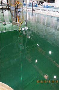
The present experiment was conducted in a deep-water offshore basin, which is 50 m long, 40 m wide, and 10 m deep in Shanghai Jiao Tong University. The whole experimental setup contained current generation system, one marine riser model, and data acquisition system as shown in Fig. 1. The physical experimental setup is shown in Fig. 2.
Fig. 1Overview of the whole experimental setup
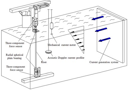
Fig. 2Physical experimental setup
2.1. Shear flow
2.1.1. Definitions on parameters of shear flow
Shear flow velocity linearly decrease along the marine risers. Therefore, shear flow velocity can be defined as follows [7]:
where is the minimum velocity of the flow in m/s, is the depth of the basin in m, is slope of the flow velocity profile.
Shear parameter can be expressed as follows:
where is the shear parameter, is the out diameter of the riser in m, is the velocity at the water surface of the basin in m/s, is the velocity at the bottom of the basin in m/s.
The Reynolds number of the shear flow can be calculated as follows:
where is the density of the water in kg/m3, is the dynamic viscosity of the water in Pa·s, is the velocity at the middle depth of the basin in m/s.
2.1.2. Shear flow facility
Shear flow was simulated by the current generation system of a deep-water offshore basin. A current generation system was installed at the right side of the basin. This system generated current through parameter control. Two current meters were used to measure the current velocity profile of the basin, as shown in Fig. 1. One was a mechanical current meter installed on the water surface. This meter can measure the surface layer shear flow velocity. The other was an acoustic Doppler current profiler installed in the middle depth of the basin. The second meter was used to measure the current profiler 1 m below the water surface. The shear flow for our experiment was generated through flow calibration, whereas the shear flow velocity profile was measured by the two current meters, as shown in Fig. 3.
Fig. 3Shear flow generated by current generation system in the experiment
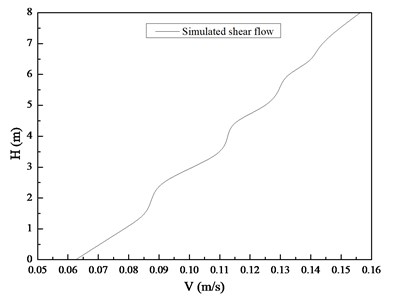
The shear flow velocity ranges from 0.0625 m/s to 0.15625 m/s. The shear flow fitting expression is . The shear parameter of the shear flow is 0.00626, whereas is 0.109375 m/s. The corresponding Reynolds number is 2761. With this range, a fully turbulent vortex street forms in the wake.
2.2. Test riser model
Experiment marine riser model was made of PVC and its main physical properties are listed in Table 1. 25 N, 35 N and 45 N pretensions were exerted on marine riser model before the beginning of the experiment. Natural frequency of the riser model can be calculated by Eq. (4) as follows [23]:
where is the natural frequency in Hz, is the pretension of the riser in experiment in N, is the length of the riser in m, is the mode order, is the bending stiffness of the riser in N·m2, is the mass per unit length in kg/m.
Table 1Main physical properties of the riser model
Item | Value |
Model length (m) | 8 |
Thickness (m) | 0.0025 |
Out diameter (m) | 0.025 |
Mass in air (kg/m3) | 1570 |
Bending stiffness (N∙m2) | 36 |
Natural frequencies of the riser model with pretension of 25, 35 and 45 N were giving in Table 2. The riser was towed vertically by the radial spherical plain bearings at the both sides of the riser, and two three-component force sensors were installed at the ends of the experiment setup as shown in Fig. 1. Lift force, drag force, and tension response were captured by three-component force sensor. The sampling rate was 1000 Hz. Acquisition time was more than 5 minutes after the shear flow velocity was stabilized.
3. Result and discussion
The dominant vibration frequencies of the lift force, drag force, and tension response can be determined on the basis of the results of their strain time histories, as obtained through fast Fourier transform (FFT).
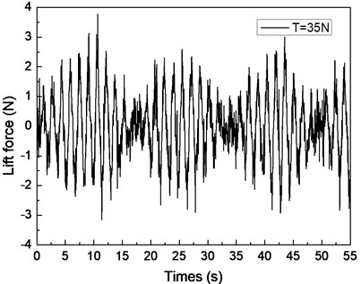
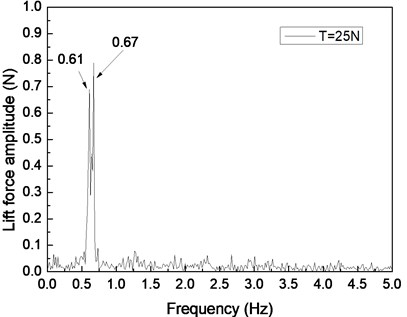
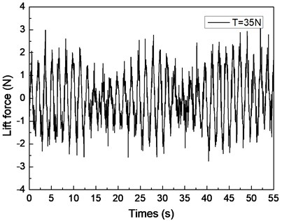
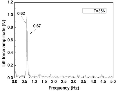
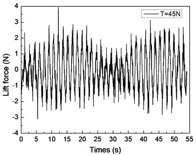
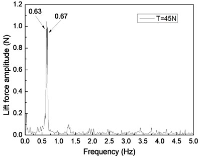
Fig. 4 shows the drilling lift force response under the shear flow given riser pretension values of 25, 35, and 45 N. Figs. 4(a), 4(c), and 4(e) are the lift force time histories, whereas Figs. 4(b), 4(d), and 4(f) show the corresponding FFT spectra. Two distinct frequencies are observed in the FFT spectra, as shown in Figs. 4(b), 4(d), and 4(f). The frequency values of 0.61 and 0.67 Hz are shown in Fig. 4(b), 0.62 and 0.67 Hz are found in Fig. 4(d), and 0.63 and 0.67 Hz are observed in Fig. 4(f). The VIV character is mainly related to both natural riser and vortex shedding frequencies.
Unlike those of uniform flow, shear flow velocities linearly decreased along the axial direction of the riser, indicating that the vortex shedding frequencies varied. Vortex shedding frequency can be determined by using the well-known Strouhal relation as follows:
where is the vortex shedding frequency in Hz, is the Strouhal number ( 0.18) [10], is the current speed in m/s, and is the riser outer diameter in m. The shear flow velocity in our experiment ranges from 0.0625 m/s to 0.15625 m/s. The vortex shedding frequencies under the shear flow clearly varied with the changing flow velocity along the axial direction of the riser. The Strouhal relation calculated a vortex shedding frequency range of 0.45 Hz to 1.125 Hz in our experiment.
The first-order natural frequencies of the riser in water are 0.45, 0.52, and 0.56 Hz, whereas the second-order natural frequencies of the riser in water are 1.18, 1.23, and 1.31 Hz with riser pretension values of 25, 35, and 45 N, respectively (Table 1). The range of the vortex shedding frequencies under the shear flow is also close to the first-order natural frequency of the riser. As the vortex shedding frequency approaches the riser natural frequency, the lock-in phenomenon occurs [5, 10]. Under this condition, the riser vibration increases significantly. Thus, a certain range of the riser that has the vortex shedding frequency close to riser natural frequency may dominate the riser vibration under the shear flow. Consequently, the riser may vibrate at the maximum riser natural frequency that corresponds to the vortex shedding frequency under the shear flow. The smaller of the two distinct frequencies in Figs. 4(b), 4(d), and 4(f) is very similar to the corresponding first-order natural frequencies of the riser. However, these frequencies are larger than the corresponding first-order natural frequencies. The difference between them is caused by the influence of the initial drag force and riser tension that periodically varies when the VIV occurs. Based on previous studies [5, 10, 11], the real-time riser natural frequencies during the experiment increased because of the initial drag force effect and periodic varying tension in VIV.
Fig. 4Lift force response of the riser under the shear flow giving the riser pretension of 25, 35, 45 N: a), c), e) are the time histories of the lift force; b), d), f) are the corresponding FFT spectrum
a)
b)
c)
d)
e)
f)
However, another frequency value at 0.67 Hz is observed in Figs. 4(b), 4(d), and 4(f). This frequency may be the vortex shedding frequency for the nonuniform vortex shedding frequency under the shear flow [25]. This scenario can be attributed to the vortex shedding frequency varying under the shear flow. Although the lock-in phenomenon dominates the riser vibration at its natural frequency, the vortex shedding from higher frequency can also affect the riser. Consequently, the shedding process under the shear flow has a natural frequency and shedding occurs at [25, 26]. Thus, the CF direction of the riser vibrates periodically with or a multiple thereof. When the lock-in phenomenon occurs in VIV, the riser also vibrate at its natural frequency .
The lift force amplitude periodically varies with time, and the riser vibration in the CF direction is recorded as a beat as shown in Figs. 4(a), 4(c), and 4(e). This condition is the so-called “beat phenomenon” of the VIV [10, 25-27]. This phenomenon could be caused by the influence of multiple frequencies appearing in the VIV under the shear flow effect. Based on a previous study [27, 28], the riser VIV could be divided into two major categories: locked-in and non-locked-in. The riser vibrates at its natural frequency in the locked-in condition, whereas the riser vibrates at multiple frequencies in non-lock-in condition. As mentioned above, the riser VIV response in our experiment contains two distinct frequencies: and . The shedding frequency interacts with the riser’s natural frequency that manifests the vibration in the CF direction in the form of a beat [25-28]. Thus, the beat phenomenon appeared in the lift force time history as shown in Figs. 4(a), 4(c), and 4(e). Several studies also observed that the beat phenomenon occurred at the non-lock-in regions under the uniform flow with the effect of multiple frequencies.
By comparing Figs. 4(a), 4(c), and 4(e), the beat phenomenon decreased with the increasing riser pretension. The phenomenon is caused by the riser’s natural frequency being close to the vortex shedding frequency . From Figs. 4(b), 4(d), and 4(f), the vortex shedding frequency is 0.67 Hz, giving the riser pretension of 25, 35, and 45 N under the same shear flow, respectively. The natural frequencies are 0.61, 0.62, and 0.63 Hz with the riser pretension of 25, 35, and 45 N under the same shear flow, respectively. The riser natural frequency increases with the increasing pretension, which decreases the interaction between the vortex shedding frequency and riser natural frequency . Consequently, the beat phenomenon decreased with the increasing riser pretension.
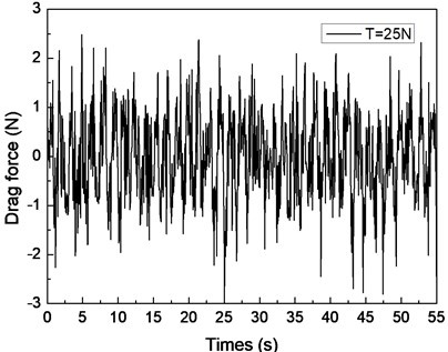
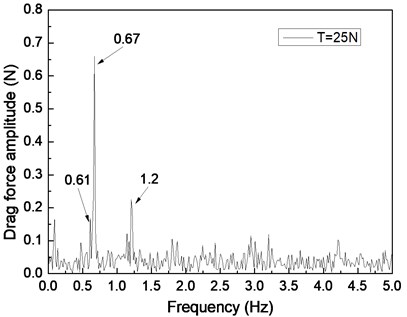
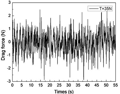
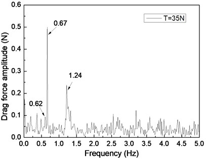
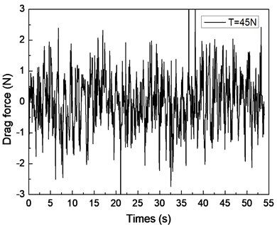
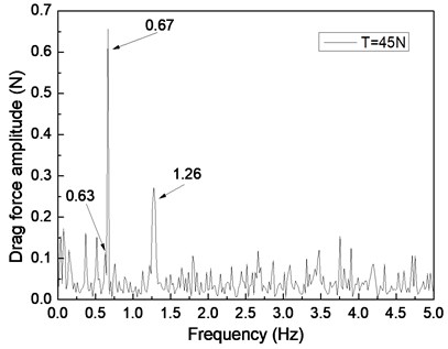
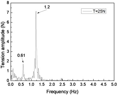
Fig. 5 depicts the drag force response of the drilling riser in the CF direction under the shear flow, giving the riser pretension of 25, 35, and 45 N. Figs. 5(a), 5(c), and 5(e) are the drag force time histories, whereas Figs. 5(b), 5(d), and 5(f) are the corresponding FFT spectra. The multiple frequencies also clearly appeared in the IL direction. The frequencies of 0.61, 0.67, and 1.20 Hz are show in Fig. 5(b); 0.62, 0.67, and 1.24 Hz are shown in Fig. 5(d); and 0.63, 0.67, and 1.26 Hz are shown in Fig. 5(f). We can easily find that two of the frequencies in the drag force FFT spectrum are the same with the corresponding frequencies in the lift force FFT spectrum. This phenomenon is caused by the interaction between the CF and IL directions when VIV occurs. This interaction between the CF and IL directions, which has been reported in many other studies [5, 10, 25], may be caused by the tension change induced by the IL and/or CF vibration. The interaction from the drag force also appears in the lift force FFT spectrum as shown in Figs. 4(b), 4(d), and 4(f), but it is unclear. As the multiple frequencies are more significant in the IL direction, the drag force time history is not stable as shown in Figs. 5(a), 5(b), and 5(c).
Previous studies [5, 10, 25, 27] on VIV with uniform current verify that the drag force frequency is twice that of the lift force for the vortex shedding form. However, the drag force frequencies are almost twice that of the lift force under the shear flow in our experimental condition. This condition can be attributed to the lock-in region dominating the vibration of the whole riser and the drag force frequency being twice that of the lift force in the lock-in region. Thus, we can also observe that the drag force frequency is twice that of the lift force under the shear flow in our experimental results.
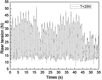
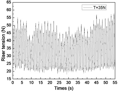
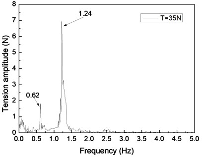
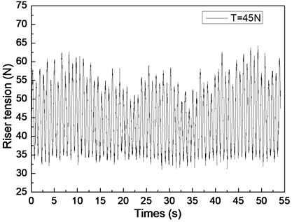
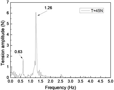
Fig. 6 shows the riser tension response of the drilling riser under the shear flow, giving the riser pretension of 25, 35, and 45 N. Figs. 6(a), 6(c), and 6(e) are the riser tension time histories, whereas Figs. 6(b), 6(d), and 6(f) are the corresponding FFT spectra. The frequencies values of 0.61 and 1.20 Hz are shown in Fig. 6(b), 0.62 and 1.24 Hz are shown in Figs. 6(d), and 0.63 and 1.26 Hz are shown in Fig. 6(f). One of the frequencies is the same with the dominant frequency of the lift force, whereas the other is equal to the dominant frequency of the drag force as shown in Figs. 6(b), 6(d), and 6(f). The riser response is clearly caused by both IL and CF vibrations.
Fig. 5Drag force response of the riser in the IL direction under the shear flow giving the riser pretension of 25, 35, 45 N: a), c), e) are the time histories of the drag force; b), d), f) are the corresponding FFT spectrum
a)
b)
c)
d)
e)
f)
Fig. 6Tension response of the riser in the axial direction under the shear flow giving the riser pretension of 25, 35, 45 N: a), c), e) are the time histories of the riser tension; b), d), f) are the corresponding FFT spectrum
a)
b)
c)
d)
e)
f)
The tension amplitudes vary, and the adjacent amplitudes of the tension periodic also increase and decrease as shown in Figs. 6(a), 6(c), and 6(e). This phenomenon is caused by the vibration frequencies in the IL direction being twice that of the CF direction, the riser vibrating twice in the IL direction, and the riser vibrating once in the CF direction. Thus, when the riser vibrates in the IL direction for the first time, the superimposed vibration from the CF direction is small. However, when the riser vibrates in the IL direction for the second time, the superimposed vibration from the CF direction is clear. Consequently, the adjacent amplitudes of the tension periodic increase and decrease. As mentioned above, the multiple frequencies appear in both IL and CF directions, so the riser tension time history varies. In conclusion, the riser response is caused by both the vibrations in the CF and IL directions, and its characteristic is consistent with the two directions.
VIV is clearly inhibited by increasing riser pretension. The dominant frequencies also increase with increasing riser tension under shear flow. These experimental results agree with the results of previous studies because the riser natural frequency and VIV characteristics are determined by the physical properties and pretension of the riser [5, 10]. Increasing riser pretension can increase the riser natural frequency and inhibit riser vibration. The riser may vibrate at a certain natural frequency under shear flow. Consequently, the dominant frequency increases with increasing riser pretension under shear flow.
In conclusion, a similar experiment for marine riser was carried out to investigate the lift force, drag force and tension response in VIV under the shear flow. Marine riser is the typical slender flexible pipe. The VIV mechanism is mainly determined by bending stiffness, riser tension, and ocean environment [5, 10]. And the riser model used in our experiment is made of PVC. Due to the small bending stiffness and tension as shown in Table 1, riser model in our experiment also has similar property as the slender flexible pipe [21]. Under the experimental ocean currents, VIV occurred as shown in Fig. 4 to Fig. 6. Accordingly, both of the VIV mechanisms for full-scale riser and model riser are typical problems of slender flexible pipe under the effect of ocean currents. Therefore, the basic VIV mechanisms under shear flow are similar. Thus, we only used a small-scale model in our experimental test, the conclusions of this study may also serve as a reference for a real-world full-scale riser in the ocean currents.
4. Conclusion
By analyzing the experiment results, the following conclusions can be drawn:
1) The dominant frequency of the lift force is similar to the natural frequency of the riser under the shear flow and the dominant frequency of the drag force is also twice of the dominant frequency of the lift force under the shear flow in our experimental condition which is consistent with the result under the uniform flow.
2) Multiple frequencies are appeared for nonuniform vortex shedding frequency and the interaction between the IL and CF vibration.
3) Beat phenomenon is observed in time history of lift force for the effect of the riser natural frequency and the vortex shedding frequency , and beat phenomenon decreased with the increasing riser pretension.
4) The VIV features determine the riser tension response. Dominant frequencies of the riser tension are consistent with the IL and CF dominant frequency, and amplitudes of the tension are not uniform and the adjacent amplitudes of the tension periodic also increase and decrease
5) VIV is obvious inhibited with increasing riser pretension and the dominant frequencies also increase with increasing riser tension under the shear flow which are agree with the previous studies.
References
-
Williamson C. H. K., Roshko A. Vortex formation in the wake of an oscillating cylinder. Journal of Fluids and Structures, Vol. 2, Issue 4, 1988, p. 355-381.
-
Govardhan R., Williamson C. H. K. Vortex induced motions of a tethered sphere. Journal of Wind Engineering and Industrial Aerodynamics, Vol. 69, Issue 71, 1997, p. 375-385.
-
Govardhan R., Williamson C. H. K. Modes of vortex formation and frequency response for a freely vibrating cylinder. Journal of Fluid Mechanics, Vol. 420, 2000, p. 85-130.
-
Jauvtis N., Williamson C. H. K. Vortex-induced vibration of a cylinder with two degrees of freedom. Journal of Fluids and Structures, Vol. 17, 2003, p. 1035-1042.
-
Williamson C. H. K., Govardhan R. A brief review of recent results in vortex-induced vibrations. Journal of Wind Engineering and Industrial Aerodynamics, Vol. 96, Issues 6-7, 2008, p. 713-735.
-
Vandiver J. K. Dimensionless parameters important to the prediction of vortex-induced vibration of long, flexible cylinders in ocean currents. Journal of Fluids and Structures, Vol. 7, Issue 5, 1993, p. 423-455.
-
Vandiver J. K. Predicting lock-in on drilling risers is sheared flows. Proceedings of the Flow-Induced Vibration Conference, Lucerne, Switzerland, 2000.
-
Kaasen K. E., Halvor L., Solaas F., Vandiver J. K. Norwegian Deepwater Program: analysis of vortex-induced vibrations of marine risers based on full-scale measurements. Offshore Technology Conference OTC No. 11997, Houston, Texas, USA, 2000.
-
Vikestad K., Vandiver J. K., Larsen C. M. Added mass and oscillation frequency for a circular cylinder subjected to vortex-induced vibrations and external disturbance. Journal of Fluids and Structures, Vol. 14, Issue 7, 2000, p. 1071-1088.
-
Sarpkaya T. A critical review of the intrinsic nature of vortex-induced vibrations. Journal of Fluids and Structures, Vol. 19, Issue 4, 2004, p. 389-447.
-
Trim A. D., Braaten H., Lie H., Tognarelli M. A. Experimental investigation of vortex-induced vibration of long marine risers. Journal of Fluids and Structures, Vol. 21, Issue 3, 2005, p. 335-361.
-
Franzini G. R., Fujarra A. L. C., Meneghini J. R., Korkischko I., Franciss R. Experimental investigation of vortex-induced vibration on rigid, smooth and inclined cylinders. Journal of Fluids and Structures, Vol. 25, Issue 4, 2009, p. 742-750.
-
Raghavan K., Bernitsas M. M. Experimental investigation of Reynolds number effect on vortex-induced vibration of rigid circular cylinder on elastic supports. Ocean Engineering, Vol. 38, Issues 5-6, 2011, p. 719-731.
-
Kiya M., Tamura H., Arie M. Vortex shedding from a circular cylinder in moderate Reynolds number shear flow. Journal of Fluid Mechanics, Vol 101, Issue 4, 1980, p. 721-735.
-
Kwon T. S., Sung H. J., Hyun J. M. Experimental investigation of uniform-shear flow past a circular cylinder. ASME Journal of Fluids Engineering, Vol. 114, Issue 3, 1992, p. 457-460.
-
Balasubramanian S., Skop R. A. A nonlinear oscillator model for vortex shedding from cylinders and cones in uniform and shear flows. Journal of Fluids and Structures, Vol. 10, Issue 3, 1996, p. 197-214.
-
Vandiver J. K., Allen D. W., Li L. The occurrence of lock-in under highly sheared conditions. Journal of Fluids and Structures, Vol. 10, Issue 5, 1996, p. 555-561.
-
Kurose R., Komori S. Drag and lift forces on a rotating sphere in a linear shear flow. Journal of Fluid Mechanics, Vol. 384, 1999, p. 183-206.
-
Lei C., Cheng L., Kavanagh K. A finite difference solution of the shear flow over a circular cylinder. Ocean Engineering, Vol. 27, Issue 3, 2000, p. 271-290.
-
Kang S. Uniform-shear flow over a circular cylinder at low Reynolds numbers. Journal of Fluids and Structures, Vol. 22, Issue 4, 2006, p. 541-555.
-
Sumner D., Akosile O. O. On uniform planar shear flow around a circular cylinder at subcritical Reynolds number. Journal of Fluids and Structures, Vol. 18, Issues 3-4, 2006, p. 441-454.
-
Marcollo H., Hinwood J. B. On shear flow single mode lock-in with both cross-flow and in-line lock-in mechanisms. Journal of Fluids and Structures, Vol. 22, Issue 2, 2006, p. 197-211.
-
Lie H., Kaasen K. E. Modal analysis of measurements from a large-scale VIV model test of a riser in linearly sheared flow. Journal of Fluids and Structures, Vol. 22, Issue 4, 2006, p. 557-575.
-
Huang K., Chen H. C., Chen C. R. Vertical riser VIV simulation in sheared current. International Society of Offshore and Polar Engineers, Vol. 22, 2012, p. 142-149.
-
Gabbai R. D., Benaroya H. An overview of modeling and experiments of vortex-induced vibration of circular cylinders. Journal of Sound and Vibration, Vol. 282, Issues 3-5, 2005, p. 575-616.
-
Zhongdi Su, Yu Liu, Hongjun Zhang, Dongfei Zhang Numerical simulation of vortex-induced vibration of a square cylinder. Journal of Mechanical Science and Technology, Vol. 21, 2007, p. 1415-1424.
-
Goswami I., Scanlan R. H., Jones N. P. Vortex-induced vibration of circular cylinders – part 1: experiment data. Journal of Mechanical Science and Technology, Vol. 21, Issue 9, 2007, p. 2270-2287.
-
Wu T., Kareem A. Vortex-induced vibration of bridge decks: a Volterra series based model. Journal of Engineering Mechanics, Vol. 139, Issue 12, 2013, p. 1831-1843.
About this article

The authors gratefully acknowledge the financial support of Young Scholars Development Fund of SWPU (201599010089).
