Abstract
Three dimensional responses of riser subjected to Vortex Induced Vibration (VIV) are investigated. Proportionality relations of stress and fatigue damage are mentioned. A computer code has been developed for time domain modeling of VIV of riser accounting for both Cross-Flow (CF) and In-Line (IL) vibration. The wake oscillator model is used to calculate the VIV of each strip. The wake oscillators are coupled to the dynamics of the long riser, while the Newmark-beta method is used for evaluating the structural dynamics of riser. The wake dynamics, including IL and CF vibrations, is represented using a pair of non-linear Van der Pol equations that solved using modified Euler method. The existing experimental and numerical results for stepped and sheared current are used to validate the proposed model and the results show reasonable agreement. The proposed model was implemented on Amir-Kabir semi-submersible riser deployed at the water depth of 713 meters of Caspian Sea. CF/IL VIV of this riser is simulated for various current velocities. The results show that although displacement amplitude of IL direction is lower than CF direction but because of higher curvature, stress values of IL direction for some cases can be higher than CF direction. Also because of higher frequency of IL direction, fatigue damage of this direction can be higher than CF one in some cases. It is shown that with increasing of current velocity; however, variation of displacement amplitude of two directions is low but stress increased and fatigue damage also increased with higher rate. For lower velocities which the modes are controlled with tension, stress and fatigue damage of IL direction is higher than CF direction.
1. Introduction
Deep water marine risers suffer from Vortex Induced Vibration (VIV) due to ocean currents, result in large amplitude vibrations in both Cross-Flow (CF) and In-Line (IL) directions. When the vortex shedding frequency approaches the natural frequency of a marine riser, the vortices shed at a frequency close to natural frequency of the riser, which is called vortex shedding lock-in or synchronization. Under these conditions, large resonant oscillations take place that will reduce the fatigue life significantly. Recent studies show that VIV of riser at direction of IL has significant contribution to responses of deep water risers. Although displacement amplitude of riser in IL direction is lower than CF, but recent experiments have evidenced that because of doubled oscillating frequency of IL VIV, fatigue damage induced by IL direction may contribute as much as CF direction [1-3]. Many experimental studies [4-7] is done on the coupled response of CF and IL and show that with increasing of CF response amplitude, the IL excitation force would be significantly magnified. Vandiver investigated the relationship between IL and CF vibration. He showed a quadratic relationship between IL and CF motion under lock-in and non-lock-in conditions [8]. Xue et al. proposed a model for prediction of VIV fatigue damage of riser accounting for both CF and IL vibrations based on the energy equilibrium theory and the experimental data of a rigid cylinder [9]. Ge et al. presented a time domain model to study the vibrations of long slender cylinders placed in shear flow. They found in the two-degree of freedom VIV experiment that the trajectory of cylinder exhibited a reverse “C” shape and that, the absolute value of the natural vibration frequency of cylinder is also one of the important parameters affecting its VIV behavior [10]. Srinil and Zanganeh proposed an advanced model for predicting a two-dimensional coupled CF/IL VIV of a flexibly mounted circular cylinder in a uniform flow based on double Duffing-Van der Pol oscillators with the two structural equations containing both cubic and quadratic nonlinear terms [11]. Sun et al. studied the fatigue damage of a long deepwater riser undergoing IL and CF VIV in deepwater using pseudo-excitation method. They used the strip theory and the discrete vortex method to calculate the VIV of each strip [12]. Mao et al. perform an experiment to investigate VIV mechanisms under shear flow. Results show that multiple frequencies are appeared for nonuniform vortex shedding frequency and interaction between the IL and CF vibrations [13].
Although there are some basic studies on the VIV phenomenon and related subjects in the literature, a completely reliable simulation model for predicting the VIV is still desirable. Modeling of 2-D VIV has many challenges such as complexity of the vortex hydrodynamics, the nonlinearities of structure and wake, the influence of several parameters, and the necessity to calibrate and validate the simulation model with existing experimental data. Many studies have focused on the modelling of pure CF VIV because of its observed largest response [16-23]. Very little is known about the effect of oscillating drag force and IL VIV, the coupling of CF/IL VIV, the dependence on system parameters and how to realistically model these features. In many models, the effect of structurally geometrical nonlinearities has often been ignored. Many simulation procedures are based on the Empirical coefficients in the wake oscillator rely upon calibration with experimental amplitude data and the coupling of CF/IL motions has not been considered in many studies.
Therefore, a complete wake-structure predictive model accounting for the coupled CF/IL, two-dimensional VIV, as proposed in the present study, would be valuable. In the present study responses of riser subjected to VIV are investigated and relations of stress and fatigue damage with mode number and current velocity are mentioned. A finite element procedure is used for time domain analysis of riser subjected to CF/IL VIV. The nonlinear 2-D coupled wake oscillator model was represented. Model formulation and also modeling and analysis procedure is represented. This model has been verified with existing experimental and numerical results of uniform (Chaplin et al. [14]) and linearly shear current (Lie and Kaasen [22]). Time domain simulation of 2-D VIV of a case study riser of Amir-Kabir semisubmersible placed in the Caspian Sea was carried out.
2. Riser responses
Assume the riser responds at one single frequency in CF or IL direction, the response shape consists of the associated mode-shape only, the displacements at two directions of CF and IL can be shown as:
where is riser length, is displacement amplitude of IL or CF direction and is the mode number of each direction. Using these displacements, bending moments caused by CF and IL vibration are derived as:
and are module of elasticity and moment of inertia, respectively. The normal stress in the longitudinal direction due to VIV is given as:
According to shedding frequency equation, relation of mode number with current velocity () for a tensioned string and untensioned beam are as follow [23]:
where is the Strouhal number, is external radius of riser section, is tension and is total mass. The damage proportionality relationship is as follow [23]:
where is slope parameter of S-N curve. Proportionality relations of stress and fatigue with mode number and current velocity can be obtained based on the aforementioned relations as shown in Table 1. According to this table, stress amplitude is proportional to for tension-controlled modes of vibration for two directions of CF and IL. This is proportional to for bending-controlled modes of two directions. Fatigue damage is proportional to for tension-controlled modes and for bending-controlled modes. The slope parameter is often seen to be 3.0 [24] and so fatigue damage is proportional to and for tension and bending controlled modes of vibration. This table also shows ratio of responses of IL to CF directions. Stress ratio are 4 times and 2 times of displacement ratio () for tension and bending controlled modes, respectively. Assuming 3 fatigue ratio is and for tension and bending controlled modes, respectively. So, it can be concluded that although when current velocity increased, displacement amplitude changes is very low but stress and fatigue damage amplitude increased with current velocity. This increasing for tension-controlled modes is higher than one for bending-controlled modes (4 compared to 2 for stress and compared to for fatigue).
Table 1Proportionality relations of stress and fatigue with mode number and current velocity
Mode type | Stress | Fatigue damage | |
Pure response | Ten.-Con. | ||
Ben.-Con. | |||
Ratio of IL to CF response | Ten.-Con. | ||
Ben.-Con. |
2.1. Wake oscillator model
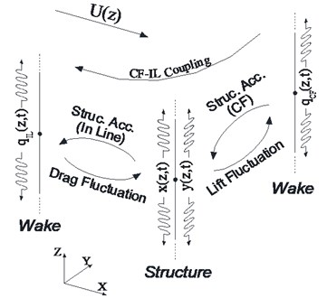
There are several different available methods for prediction of VIV response of risers such as Computational Fluid Dynamics (CFD), empirical models and experimental approaches [25]. Wake oscillator model which was first introduced by Birkoff and Zarantanello [26], is an empirical model utilizes a Van der Pol type equation to describe the effects of vortex shedding of CF direction (1-D wake oscillator model). Fig. 1 shows a schematic view of 2-D wake oscillator model that couples the equation of structural motion with a nonlinear oscillator equation that describes the fluid force for two directions of CF and IL. The dynamic response of a riser is described using the external force from the wake. The wake itself is described by a forced Van der Pol oscillator equation. The force term of the Van der Pol oscillator equation is related to the cylinder oscillation by a coupling term proportional to the cylinder’s displacement, velocity or acceleration.
Fig. 12-D wake oscillator model
2.2. Model formulation
For a Cartesian right-hand coordinate system with x and y in the horizontal plane (flow is in direction) and vertically upwards, the dynamic equations of motion of riser can be expressed as [27]:
where is the bending stiffness of cylinder, is the axial tension in cylinder and is the sum of structure mass and added fluid mass per unit length which can be explained as:
where and are masses of structure and internal fluid, respectively, is the added mass coefficient, is the fluid density, is the riser outer diameter. and are the damping coefficients due to structure and hydrodynamic forces. is given by:
where is stall parameter determined through experiment, is the current velocity, and are non-dimensional coefficients and represent the IL drag coefficient and CF lift coefficient, respectively which can be computed from following equations:
where is the vortex shedding drag coefficient and is the lift coefficient for a fixed rigid cylinder subjected to vortex shedding. Non-dimensional variables and are wake parameters of IL and CF direction respectively and introduced satisfying the following equations:
where , , , are non-dimensional parameters estimated through experiment. In this study, values of 0.3, 0.3, 12, and 12 is used for these parameters respectively. is the Strouhal frequency given by .
The right-hand side of Eq. 5 expresses the effects of riser motion on near wake. An acceleration coupling term is chosen, which can quantitatively describe some typical phenomena of VIV observed experimentally to some extent (Facchinetti et al. [27]). Finally using finite element approximation, the mass, damping and stiffness matrices and the matrix form of equation of motion can be obtained as follow:
These equations can be solved using various analysis procedures such as modal superposition or Newmark-Beta method. and are obtained from wake parameters that at each time step is computed solving Van der Pol equation.
3. System modeling
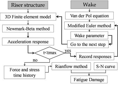
The marine riser is idealized as a tensioned Euler–Bernoulli beam. A Cartesian reference with its origin at the bottom of the riser has been used, in which the axis is parallel to the flow velocity, coincides with the vertical axis of the riser in its undeflected configuration and is perpendicular to both as shown in the Fig. 2. A MATLAB code was used in this study and a 3-D finite element model was considered for riser structure and the riser is allowed to oscillate on both axes, the stream (-axis) and the cross-wise (-axis) as shown. Each node has 6 degrees of freedom. Top tension and distributed weight and buoyancy forces are considered. The Newmark-beta method is used to solve the dynamic equation from previous section by a step-by-step time integration scheme for time domain simulation of structure behavior as shown in Fig. 3. The method applies Cauchy’s mean value theorem to express the velocity and the displacement terms of said equation, such that the update scheme is as follows:
where and are integration parameters that are chosen for controlling stability, accuracy and efficiency of the integration.
The wake oscillator model coupled with the riser dynamic equation has been extended to calculate the IL and CF response. At each node of riser, equation of motion and Van der Pol equation of wake is coupled at each time step. Van der Pol equation is solved using modified Euler method. The modified Euler method is a simple numerical procedure which can be effectively used for numerically solving this nonlinear differential equation.
The number of stress cycles and amplitudes in the time domain are determined by the rainflow counting method and then the Palmgren-Miner rule [28] is used to estimate the fatigue life of the riser for cumulative damage theory with a specified S-N curve as shown in Fig. 3.
Fig. 23-D model of riser and 2-D wake oscillator model
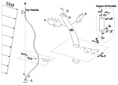
Fig. 3Time domain modeling of 2-D VIV
3.1. Validation of the model
3.1.1. Stepped current
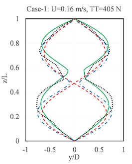
Chaplin et al carried out the laboratory VIV measurements of tensioned risers in a stepped current [14]. Properties of the riser model are listed in Table 2. Lower 6 m length of model was in a uniform current while the upper part was in still water. Nine cases of Chaplin’s experiments with various top tension and current velocity are chosen for VIV predictions and comparisons, as shown in Table 1. These experiments have been used with some researchers to verify the simulation procedures. For example, Xue et al. used a procedure based on the empirical coefficient for prediction of CF/IL VIV [29]. Also, some studies used VIVANA program [30] to simulate CF VIV. Results of the present model of this paper were compared to existing experimental and numerical results.
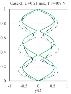
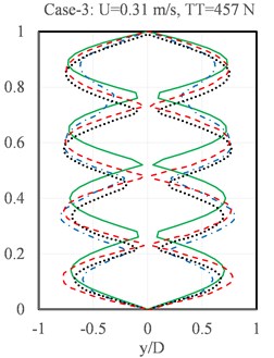
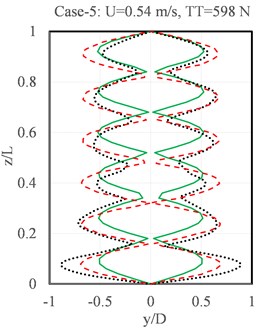
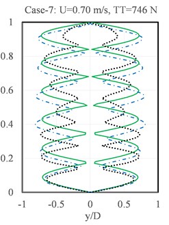
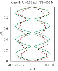
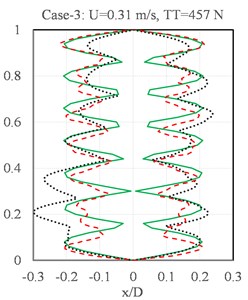
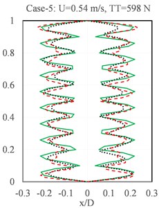
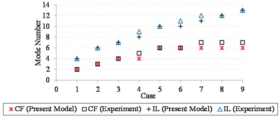
The envelopes of CF VIV amplitude are given in Fig. 4. This figure compares the results of present model with mentioned experiments, VIVANA program and Xue’s model results. It can be seen that the present model predicts the same mode number of vibration and also it is evident that amplitudes are the same as experimental results. Compared to results of VIVANA program and Xue’s model, the present model results are closer to experimental ones. The response is mainly dominated by single mode and with increasing current velocity, the higher mode is excited. The envelopes of IL VIV amplitude was compared to Chaplin’s experiments and Xue’s model in Fig. 5 that shows the efficiency of present model for simulation of IL VIV too. It can be seen that results of present model are closer to experiments compared to Xue’s model. For all cases, dominant mode number is the same. The dominant mode numbers of present model and Chaplin’s experiments are compared in Fig. 6. The prediction of the mode numbers is good and only some points have 1 mode number discrepancy.
Table 2Properties of Chaplin’s tests [14]
Properties | Values | Cases | Top tension (N) | Current speed (m/s) |
Total length (m) | 13.12 | 1 | 405 | 0.16 |
Diameter (m) | 0.028 | 2 | 407 | 0.21 |
Mass (kg/m) | 1.85 | 3 | 457 | 0.31 |
Apparent weight (N/m) | 12.1 | 4 | 506 | 0.40 |
Flexural rigidity (N/m2) | 29.9 | 5 | 598 | 0.54 |
Structural damping | 0.33 % | 6 | 670 | 0.60 |
7 | 746 | 0.70 | ||
8 | 923 | 0.85 | ||
9 | 1002 | 0.95 |
Fig. 4Comparison of the results of the present model with Chaplin’s experiments, Xue’s Model and VIVANA results for CF VIV in stepped currents
a)
b)
c)
d)
e)

Fig. 5Comparison of the results of the present model with Chaplin’s experiments, Xue’s Model and VIVANA results for IL VIV in stepped currents
a)
b)
c)

Fig. 6Comparison of the results of the present model with others for VIV in stepped currents
3.1.2. Linearly shear current
HanØtangen’s experiment was 90 m riser model was attached to a floating vessel, as shown in Fig. 7 [22].
Fig. 7Configuration of experiment [23]
![Configuration of experiment [23]](https://static-01.extrica.com/articles/18293/18293-img15.jpg)
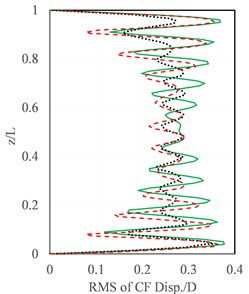
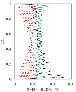
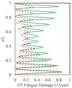
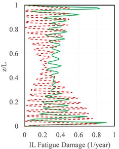
That with moving of the vessel at a constant speed, the riser was exposed to a linearly sheared current. Table 3 listed the main parameters of the riser. Fig. 8(a) compares the Root Mean Square (RMS) values of the CF VIV along the riser with this experiment and also Xue’s model results. According to this figure results of the present model and experimental data are close and show that mode 11 and mode 12 are the dominant modes. Fig. 8(b) shows the RMS values of the IL VIV displacement along the riser. It can be found that the present model has good agreement with experimental measurements and that the present finite element model can be used for response prediction of riser VIV for both CF and IL directions. Fig. 9 compares fatigue damage results of present model with Xue’s model for two directions of CF and IL, which shows accuracy of developed code to estimate fatigue damage of riser in shear current.
Table 3Properties of HanØtangen’s riser [22]
Properties | Values |
Length (m) | 90.0 |
Outer diameter (m) | 0.03 |
Inner diameter (m) | 0.026 |
Mass (kg/m) | 2.27 |
Elastic modulus (N/m2) | 2.1×10¹¹ |
Top tension (N) | 3700 |
Top velocity (m/s) | 0.54 |
Fig. 8RMS values of the: a) CF VIV displacement along the riser, b) IL VIV displacement along the riser
a)
b)

Fig. 9Comparison of fatigue damage of the riser: a) CF direction, b) IL direction
a)
b)
4. Case study
The presented model is used for VIV response prediction of existing top tension riser of Amir-Kabir semisubmersible placed in Caspian Sea. Based on the present position of semisubmersible, length of the riser is 713 m. Table 4 shows properties of this riser.
Table 4Specifications of riser of Amir-Kabir semisubmersible
Specification | Value |
Length | 713 (m) |
Bending stiffness (EI) | 922540 (kN.m2) |
Axial stiffness (EA) | 10320240 (kN) |
Mass per unit length (m/L) | 1080 (kg/m) |
Top Tension | 2000 (kN) |
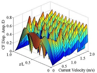
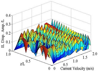
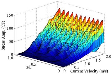
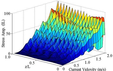
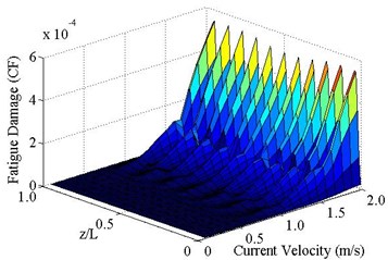
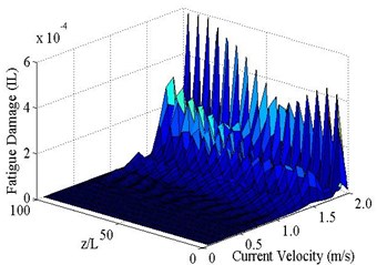
Fig. 10(a) and (b) show envelope of displacement for various current velocity up to 2 m/s in CF and IL direction, respectively. It can be seen that variation of maximum displacement of riser is approximately low for various current velocities for two directions and is between 0.39D and 0.76D for CF direction and 0.09D and 0.21D for IL direction. Envelope of stress versus current velocity is shown on Fig. 10(c) and d for CF and IL direction, respectively. It can be seen that maximum stress for two directions of CF and IL is amplified with increasing current velocity, although displacement amplitude variation with current velocity is low. This is because when current velocity is increased, upper modes of vibration are dominant and for same displacement amplitude upper modes have higher curvature and also higher moment and stress. So, because of higher dominant mode number of IL compared to CF, ratio of stress of IL to CF is higher than ratio of displacement of IL to CF for all current velocity. It is evident that variation of stress with current velocity is parabolic for low current velocities (tension-controlled modes) and is linear for higher velocities (bending-controlled modes) which are consistent with aforementioned equation of section one. Fig. 10(e) and (f) shows fatigue damage envelope of riser in two directions of CF and IL, respectively. It can be seen that when current velocity increase damage is amplified in two directions rapidly. The variation of damage is more than that of stress because of increasing the number of stress cycles with mode number. In section one it is shown that fatigue damage is proportional to and for tension and bending controlled modes. Approximately these proportionalities can be seen in this figure. According to this figure CF displacement is very higher than IL one, but stress of IL is very close to CF one and IL fatigue damage is very close to CF one and in some cases, is bigger than it. This issue is more obvious in tension-control modes of vibration (low current velocities) compared to bending-controlled modes of vibration because ratio of IL mode number to CF in tension-controlled modes is 2 compared to of bending-controlled modes of vibration.
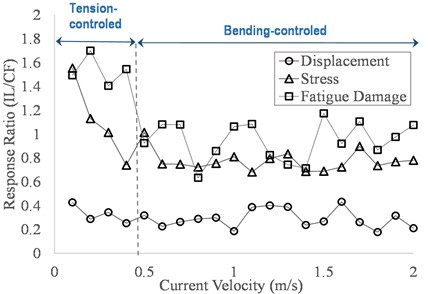
Fig. 11 shows the ratio of responses of IL to CF direction for various current velocities. It can be seen that although displacement ratio is constant approximately, but stress ratio reduces with current velocity and for lower velocities which tension modes is dominant, stress ratio is higher and stress of IL direction is bigger than CF direction. The same results can be concluded from section one which stress ratio of tension-controlled modes is twice of bending-controlled modes. For current velocity equals to 0.1 m/s dominant mode number of CF and IL directions are equals to 1 and 3 respectively and stress ratio of IL to CF direction is approximately equals to 1.5, which shows amplification of higher curvature effect. The same trend can be seen for fatigue damage ratios. Approximately in many cases damage ratios is higher than stress ratios. Frequency of vibration in IL direction is twice of this value for CF direction and according to equation of riser frequency, it can be concluded that for tension-controlled modes of vibration ratio of IL mode number to CF one is 2. This ratio for bending-controlled modes is . So, number of stress cycles in IL direction is more than that for CF direction. So, ratio of fatigue damage of IL direction to CF ones is higher than stress ratio of two directions as shown in Fig. 11. This situation is more highlight for tension-controlled modes of vibration.
Fig. 10Envelopes of displacement, stress and fatigue damage of riser in CF and IL directions
a)
b)
c)
d)
e)
f)
Fig. 11Ratio of responses of IL to CF direction
5. Conclusions
In this paper responses of riser subjected to Vortex Induced Vibration (VIV) are investigated. A finite element model for simulation of riser subjected to Cross-Flow (CF)/In-Line (IL) Vortex Induced Vibration (VIV) was proposed. A computer code has been developed for time domain modeling of VIV of riser accounting for both CF and IL vibration. Verification of model with existing experimental and numerical data was done for uniform and shear current profile. Results show that the present model predicts the responses of riser for two directions of CF and IL very well. The existing riser of Amir-Kabir semisubmersible platform located in Caspian Sea was chosen as a case study to investigate the VIV of the riser within different environmental conditions. The results show that although displacement amplitude of IL, compared to CF direction is low, but because of higher curvature, stress values of IL direction for some cases is important and must be considered. It was shown that ratio of stress of IL to CF direction for tension dominated modes is high and with increasing of mode number, this value decrease. At current velocity equals to 0.1 m/s, ratio of stress for IL to CF is very high (approximately 1.5), because dominant mode number of IL and CF are 3 and 1 respectively. This condition can take place for other velocity also and must be considered. This paper shows that when current velocity increase, displacement amplitude approximately is constant but variation of stress and damage is high. Although CF displacement is very higher than IL one, but stress of IL is very close to CF one and IL fatigue damage in many cases is bigger than it which this issue is more obvious in tension-control modes of vibration compared to bending-controlled modes of vibration.
References
-
Dahl J. M., Hover F. S., Triantafyllou M. S., Oakley O. H. Dual resonance in vortex-induced vibrations at subcritical and supercritical Reynolds numbers. Journal of Fluid Mechanics, Vol. 643, 2010, p. 395-424.
-
Yin D., Larsen C. M. Experimental and numerical analysis of forced motion of a circular cylinder. Proceedings of the 30th International Conference on Offshore Mechanics and Arctic Engineering, Rotterdam, Netherlands, 2011.
-
Kang Z., Jia L. An experimental investigation of one- and two-degree of freedom VIV of cylinder. Acta Mechanica Sinica, Vol. 29, Issue 2, 2013, p. 284-293.
-
Jauvtis N., Williamson C. H. K. The effect of two degrees of freedom on vortex-induced vibration at low mass and damping. Journal of Fluid Mechanics, Vol. 509, 2004, p. 23-62.
-
Sumer B., FredsØe J. Hydrodynamics Around Cylindrical Structures. World Scientific, 2006.
-
Stappenbelt B., Lalji F., Tan G. Low mass ratio vortex-induced motion. 16th Australasian Fluid Mechanics Conference, Australia, 2007.
-
Blevins R. D., Coughran C. S. Experimental investigation of vortex-induced vibration in one and two dimensions with variable mass, damping, and Reynolds number. Journal of Fluids Engineering. Vol. 131, Issue 10, 2009, p. 101202.
-
Vandiver J. K., Jong J. Y. The relationship between in-line and cross-flow vortex-induced vibration of cylinders. Journal of Fluids and Structures, Vol. 1, Issue 4, 1987, p. 381-399.
-
Xue H., Wenyong T., Shengkun Z. Simplified Model for Evaluation of VIV-induced Fatigue Damage of Deepwater Marine Risers. Journal of Shanghai Jiaotong University (Science), Vol. 14, Issue 4, 2009, p. 435-442.
-
Ge F., Lu W., Wang L., Hong Y. S. Shear flow induced vibrations of long slender cylinders with a wake oscillator model. Acta Mechanica Sinica, Vol. 27, Issue 3, 2011, p. 330-338.
-
Srinil N., Zanganeh H. Modelling of coupled cross-flow/in-line vortex induced vibrations using double Duffing and van der Pol oscillators. Ocean Engineering, Vol. 53, 2012, p. 83-97.
-
Sun L., Liu C. F., Zong Z., Dong X. L. Fatigue damage analysis of the deep water riser from VIV using pseudo-excitation method. Marine Structures, Vol. 37, 2014, p. 86-110.
-
Mao L., Liu Q., Wang G., Zhou S. Lift force, drag force, and tension response in vortex-induced vibration for marine risers under shear flow. Journal of Vibroengineering, Vol. 18, Issue 2, 2016, p. 1187-1197.
-
Chaplin J. R., Bearman P. W., Cheng Y., Fontaine E., Graham J. M. R., Herfjord K., Huera Huarte F. J., Isherwood M., Lambrakos K., Larsen C. M., Meneghini J. R., Moe G., Pattenden R. J., Triantafyllou M. S., Willden R. H. J. Blind predictions of laboratory measurements of vortex-induced vibrations of a tension riser. Journal of Fluids and Structures, Vol. 21, Issue 1, 2005, p. 25-40.
-
Bishop R. E. D., Hassan A. Y. The lift and drag forces on a circular cylinder oscillating in a flowing fluid. Proceedings of the Royal Society of London, 1964, p. 51-75.
-
Hartlen R. T., Currie I. G. Lift-oscillator model of vortex induced vibration. Journal of Engineering Mechanics, Vol. 96, Issue 5, 1970, p. 577-591.
-
Sarpkaya T. A critical review of the intrinsic nature of vortex-induced vibrations. Journal of Fluids and Structures, Vol. 19, Issue 4, 2004, p. 389-447.
-
Gabbai R. D., Benaroya H. An overview of modeling and experiments of vortex-induced vibration of circular cylinders. Journal of Sound and Vibration, Vol. 282, Issues 3-5, 2005, p. 575-616.
-
Srinil N., Wiercigroch M., O’Brien P. Reduced-order modelling of vortex induced vibration of catenary riser. Ocean Engineering, Vol. 36, Issues 17-18, 2009, p. 1404-1414.
-
Srinil N. Analysis and prediction of vortex-induced vibrations of variable tension vertical risers in linearly sheared currents. Applied Ocean Research, Vol. 33, Issue 1, 2011, p. 41-53.
-
Komachi Y., Mazaheri S., Tabeshpour M. R. The effect of shifting natural frequency on the reduction of Vortex-Induced Vibrations of marine risers. International Journal of Coastal and Offshore Engineering, Vol. 1, Issue 1, 2017, p. 9-16.
-
Lie H., Kaasen K. E. Modal analysis of measurements from a large-scale VIV model test of a riser in linearly sheared flow. Journal of Fluids and Structures, Vol. 22, Issue 4, 2006, p. 557-575.
-
Baarholm G. S., Larsen C. M., Lie H. On fatigue damage accumulation from in-line and cross-flow vortex-induced vibrations on risers. Journal of Fluids and Structures, Vol. 22, 2006, p. 109-27.
-
Design of Steel Structures – Annex C –Fatigue Strength Analysis. NORSOK Standard, 1998.
-
The Specialist Committee on Vortex Induced Vibrations Committee. Proceedings of 25th ITTC, Volume II, 2008.
-
Birkoff G., Zarantanello E. J. Wakes and Cavities. Academic Press, New York, USA, 1957.
-
Facchinetti M. L., Langre E., Biolley F. Coupling of structure and wake oscillators in vortex-induced vibrations. Journal of Fluids and Structures, Vol. 19, Issue 2, 2004, p. 123-140.
-
Miner M. A. Cumulative damage in fatigue. Journal of Applied Mechanics, ASME, Vol. 12, 2014, p. 159-164.
-
Xue H., Tang W., Qu X. Prediction and analysis of fatigue damage due to cross-flow and in-line VIV for marine risers in non-uniform current. Ocean Engineering, Vol. 83, 2014, p. 52-62.
-
Larsen C. M., Vikestad K. VIVANA-Theory Manual Version 3.4. Norwegian Marine Technology Research Institute, Trondheim, Norway, 2005.
About this article

