Abstract
The riser system acts as the vital link between the subsea blow-out preventer and the drilling platform. Affected by factors like top tension and marine environmental forces, the riser undergoes deformation and wear, carrying the risk of environmental pollution and financial losses upon failure. Hence, this study examines the riser's dynamic response to marine environmental loading. Initially, the motion differential equation for the riser system under the influence of nonlinear oceanic load is deduced using the principle of minimum potential energy and the variational method for extremum seeking. Subsequently, a nonlinear wave-current load model based on the Morrison equation is established, and the resulting equation is discretized into a finite element model using third-order Hermite interpolation function and the Galerkin weighted residual method. Finally, the dynamic response of the riser is scrutinized employing the Newmark numerical integration method. The study also investigates the impact of both oceanic environmental parameters and drilling parameters on the riser’s dynamic behavior. Comparative analysis of the numerical results reveals that the maximum displacement of the riser occurs at the middle section, whereas the maximum deflection angle is observed at the end of the riser. The periodicity of the deflection angle response is influenced by the position of the riser, showing a trend of decreasing and then increasing from the middle section towards the ends. Notably, the top tension and the velocity of the surface tidal current significantly affect the dynamic behavior of the riser. The findings of this study provide a theoretical foundation for the assessment of riser reliability and the determination of operational parameters.
Highlights
- Dynamic Deformation Patterns: Numerical analysis reveals that the riser exhibits distinct deformation patterns, with the maximum in-line displacement occurring at the middle section and a notable "reverse offset" phenomenon observed. This asymmetry provides crucial insights into the dynamic behavior of risers under marine environmental loading.
- Periodicity Variations along the Riser: The study uncovers a nuanced trend in the periodicity of deflection angle responses along the riser. Starting from the middle section, there is a decreasing trend followed by an increasing trend towards the ends. Particularly, the middle section displays the highest degree of periodicity, highlighting the spatial variability in dynamic responses.
- Top Tension Influence: The research emphasizes the pivotal role of top tension in shaping riser behavior. Increasing top tension not only reduces the maximum displacement and deflection angle but also enhances the natural frequency. This underscores the significance of top tension in suppressing riser deformation by strengthening its bending stiffness.
1. Introduction
Offshore drilling has gained significant recognition as a widely embraced methodology for extracting energy resources. Within the domain of offshore drilling, risers play a pivotal role by establishing a vital connection between the subsea wellhead and the drilling platform. As a specialized pipeline system, risers withstand external loads while bearing internal high-pressure fluids. Consequently, it becomes imperative to thoroughly comprehend and analyze the dynamic behavior of risers in order to optimize drilling efficiency and mitigate potential risks.
Since the initiation of the Mohole drilling project in 1957, significant progress has been made in the study of the mechanical characteristics of offshore risers over the past few decades. The early theoretical investigations primarily focused on static analysis of risers, examining their mechanical behavior under stationary or quasi-stationary conditions. One major issue in early research of static analysis of risers concerned empirical formulas and theoretical models. Burke established the earliest static model of risers by describing the force state of riser elements using the fourth-order differential equation of the Euler-Bernoulli beam [1]. Based on Burke’s work, scholars simplified models of risers and utilized computer simulations to replicate actual conditions and to identify the key parameters influencing riser behavior [2-4]. With the advancement and maturity of the small-strain theory and finite element methods, they have gradually been incorporated into the static analysis of risers, demonstrating their growing significance and practical application in the field. Bernitsas et al. investigated the static state of three-dimensional nonlinear riser models using small-strain theory [5]. Subsequently, finite element methods were employed by Bernitsas to conduct static analysis of risers, in which the coupling relationship between transverse displacements and slopes generated by axial extension deformations was determined [6]. With the increasing water depths of offshore exploration and the growing complexity of marine environments, relying solely on static analysis of risers is inadequate to meet the safety production requirements. This highlights the crucial significance of dynamic response analysis. The dynamic analysis of risers includes both time-domain analysis and frequency-domain analysis. Kirk et al. utilized free vibration and rigid-body displacement to solve the tensioned beam equations, analyzing the in-line dynamic response of risers subjected to periodic excitation from surface vessels in time-domain [7]. Lei et al. formulated a nonlinear coupling model for the riser subjected to combined axial and transverse loads. Their findings highlight the substantial enhancement of lateral dynamic response due to axial excitation [8]. Duan conducted a comprehensive study on the influence of internal velocity and density on vortex-induced vibration response of flexible risers in deep sea mining. Using a validated semi-empirical time-domain prediction method that accounts for both internal and external flow, the research demonstrated notable effects of the internal flow on the riser's dominant frequency, displacement, and drag coefficient [9]. Wang et al. proposed an analytical method to predict the transverse vibration response of a jack-up riser under random wave load, which is based on Euler-Bernoulli beam theory and Mindlin-Goodman method in the frequency domain. Experimental verification was conducted to validate the accuracy of the proposed method [10]. Several studies have demonstrated that both the top tension and internal fluid play crucial roles in influencing the dynamic response of the riser [11-14]. Yuan et al. utilized the force decomposition model to establish the equations of motion for the riser and investigated the effects of vortex force, relative inertia force, and Coriolis force induced by the internal fluid on the riser [15]. Guo et al. studied the dynamic response of a top tensioned riser under combined excitation of internal solitary wave, surface wave, and vessel motion. The riser is modeled as a tensioned slender beam with dynamic boundary conditions. Numerical analysis using the finite element method reveals that the internal solitary wave exerts a dominant influence on the riser, surpassing the effects of the surface wave and vessel motion [16]. Lou et al. studied the dynamic response of a marine riser under the excitation of internal waves using a linear approximation. The numerical results showed that the internal wave resulted in circular shear flow, and the first two modes had a dominant effect on the dynamic response of the marine riser [17]. An improved method for analyzing the axial dynamic response of risers was proposed by Liu. The method was used to study the detailed influence of hydrodynamic loads on the axial dynamics of risers under different amplitudes and periods of platform motion and riser configurations [18]. Substantial evidence supports the notion that fatigue damage is a crucial factor in determining the safety of risers [19-20]. Jeong et al. studied the effects of slug flow on the dynamic response and fatigue damage of risers, for which they developed a methodology to evaluate the impacts. The study concluded that the main impact of the slug flow is the increased fatigue damage of the riser structure [21]. Kim et al. proposed a new dynamic analysis method for flexible risers, considering geometric and bending nonlinearity. The method, based on Green Lagrange strain and seabed interaction, examined the risers' dynamic response and fatigue damage. They also developed OPFLEX, a dynamic analysis program that accounted for shear deformation and varying tension in the riser [22]. Numerous researchers have developed a range of computational programs for analyzing the dynamic response of risers. Patel et al. presented the time and frequency domains analysis procedures for risers [23]. McNamara et al. employed a mixed finite element procedure to analyze the time-domain dynamic response problem of two-dimensional flexible risers [24]. Wang et al. conducted modal analysis to explore the dynamic characteristics of the riser system in the frequency domain [25].
In summary, the investigation of the dynamic behavior of risers in offshore drilling has been a focal point in research. Finite element analysis has emerged as the most efficient approach for studying the dynamic response of continuous structures like risers. Moreover, risers are subject to external nonlinear loads, which contribute to the manifestation of nonlinear characteristics in their dynamic behavior. However, Researchers have not treated nonlinear loadings of ocean in much detail. Existing literatures predominantly simplified the nonlinear loads as uniformly distributed loads and lacked explicit elucidation of the dynamic modeling and finite element analysis procedures for risers. This paper aims to comprehensively expound on the dynamic modeling and finite element solution process for risers under the influence of nonlinear loads. The dynamic response of the risers will be examined utilizing a time-domain analysis approach, and the parameter analysis will be conducted to assess the primary factors impacting the deformation of the risers. The ultimate goal of this research is to provide significant theoretical support for the accurate evaluation of the safety and reliability of risers.
2. Dynamical model of riser
The riser model depicted in Fig. 1 illustrates the connection of the riser to both the drilling platform and the subsea blowout preventer through upper and lower flexible joints. Additionally, the riser experiences non-uniform loads caused by oceanic conditions. Furthermore, the riser is filled with drilling fluid, and a drill string is operated within it. To simplify the theoretical derivation and maintain the rationality of the model, the factors with minor impacts on the model are ignored, and some assumptions are proposed as follows:
1) The riser is a type of rigid pipe that undergoes minor deformation, making it suitable for analysis under the assumption of large strain and small deformation;
2) The riser is made of homogeneous and isotropic materials, and its deformation remains within the linear elastic range;
3) The influence of various small tubes within the riser on its stiffness is neglected due to the thinness of the kill and choke lines;
4) The collision effect of the drill string on the riser is not taken into consideration;
5) The sway motion of the platform is not considered.
Fig. 1The schematic diagram of an offshore platform riser
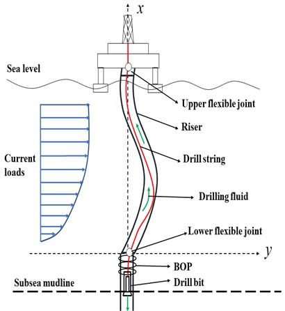
When dynamically modeling the riser depicted in Fig. 1, it is considered as a collection of interconnected elastic beam elements. A Cartesian coordinate system is established, and a beam element at arbitrary position is selected for force analysis, as illustrated in Fig. 2. In this figure, the -axis represents the in-line direction, while the -axis corresponds to the axis direction of the riser. The variables and represent the axial and in-line displacements of the riser, respectively. is the section bending moment, and is the section tension. m signifies the vibration mass of the riser per unit length, and represents the external load applied to the riser per unit length.
Fig. 2Riser element model
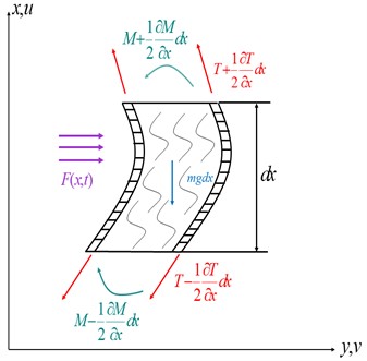
The deformation energy, kinetic energy, and external work of the riser element can be mathematically expressed using the model.
The deformation energy of a riser element is attributed to internal forces such as the section bending moment and tension . By employing the moment-curvature equation, the bending moment can be expressed as follows:
where represents the elastic modulus and denotes the moment of inertia of the section.
The deformation energy generated by work done of bending moments is expressed as:
where is the rotation angle of the riser.
By substituting Eq. (1) into Eq. (2), the expression for the deformation energy caused by the bending moment can be derived as follows:
The deformation energy resulting from tension work can be represented as:
Hence, the deformation energy of the riser element can be described as:
The riser may undergo vibration due to nonlinear and time-varying loads, and the kinetic energy of the riser element can be represented as follows:
The loads acting on the riser primarily consist of nonlinear and time-varying loads, as well as the friction damping force between the drilling fluid and the riser. However, this study mainly focuses on the impact of external nonlinear loads on the riser, and previous research has suggested that the influence of viscous frictional damping on the motion characteristics of the riser is negligible. Therefore, the work done by the friction damping force is disregarded. The work done by the external load on the riser element can be expressed as follows:
Based on the above analysis, the potential energy of riser element can be described as:
Therefore, the total energy of the riser in a given period is expressed as follows:
where represents the total length of the riser.
It is evident from Eq. (9) that is the functional of in-line displacement . According to the principle of minimum potential energy, the most probable displacement should yield the minimum of , in other words, should satisfy Euler’s equation. is a functional of multivariate functions, and contains higher derivatives of self-varying functions. The corresponding Euler equation can be derived as follows:
with , , , , , , .
By substituting Eq. (9) into Eq. (10), the differential equation of riser system motion can be obtained as follows:
Due to the equation is a fourth-order derivative, four boundary conditions are required to determine the solution of the equation. Assuming the rotational stiffness of the lower flexible joint of the riser is denoted as , the lower boundary condition of the riser can be described as:
Additionally, the rotational stiffness of the upper flexible joint of the riser is set to , Since the sway motion of the platform is ignored, the boundary condition on the riser is expressed as:
Typically, tension in excess of the floating weight of riser is provided by the top tensioner. As a result, the corresponding bottom tension will be generated at the bottom joint of the riser, as shown in Fig. 3.
Fig. 3The schematic diagram of riser tension
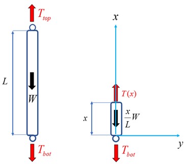
According to the force balance:
where is the tension at the top of the riser while is the tension at the bottom of the riser, and W is the floating weight of the riser. , where is riser density, is seawater density, and g is gravitational acceleration. represents the outer diameter of the riser, and represents the thickness of the riser.
Thus, the tension of any section is denoted by:
The vibration mass per unit length of riser includes the mass of the riser itself, the mass of the internal drilling fluid, and the mass of the seawater attached to the external surface, i.e.:
where is the riser mass per unit length, is the drilling fluid mass in the riser per unit length, and is the seawater mass attached to the riser surface per unit length. , in which represents the coefficient of inertia force.
According to Morrison's equation, the action of ocean current on riser can be divided into viscous effect and additional mass effect, namely drag force and inertia force. Since the seawater particle moves back and forth in a periodic manner, their velocities alternate between positive and negative values. The in-line drag force can be expressed as:
where is the relative velocity of seawater particle and riser in the in-line direction, is the projected area of the riser per unit length perpendicular to the flow direction, and is the viscosity coefficient.
The in-line inertial force, which comprises the inertial force generated by the riser itself and the inertial force generated by the external seawater mass, is directly proportional to the acceleration:
where, is the drainage volume per unit length of riser, . is the relative acceleration of seawater particle and riser in the in-line direction, and is the additional mass coefficient.
According to the second-order Stokes wave theory, the seawater particle velocity and acceleration are as follows:
where is the wave height, is the wave period, and is the wave number. represents the water depth, and denotes the wave frequency.
According to Wilson’s theory, the flow velocity in the shallow area is calculated by the following equation:
where is the wind current speed, is the tidal current speed. , in which is the wind speed of sea surface and is the wind speed factor. , where is the tidal range, represent the mean tidal range of spring tide, middle tide and neap tide, denote the mean current velocity of sea surface during spring tide, middle tide and neap tide.
Therefore, the external load per unit length riser is written as:
In order to simplify the solution process and ensure the solution accuracy, the Krylov-Bogoliubov method is employed to linearize the velocity square term in Eq. (22) as follows:
where is the damping linearization factor. , in which represents the amplitude of .
3. Finite element model of riser
Considering the characteristics of the differential equation governing the motion of the riser, the finite element method is utilized to discretize the equation. In work environment, risers exhibit a variety of curve forms. The third-order Hermite interpolation function excels at providing finer approximations for intricate function shapes, proving especially valuable in situations demanding heightened accuracy. Hence, incorporating the Hermite cubic interpolation function as the shape functions for riser elements, the in-line displacement of the riser is represented by:
with , , represent the displacements of nodes 1 and 2, while signify the rotations of nodes 1 and 2, respectively..
Given the intricate nonlinear and unsteady characteristics inherent in riser dynamics, opting for the Galerkin weighted residual method to discretize the motion model of the riser allows for an effective capture of the system’s dynamic behavior. The general expression of the Galerkin weighted residual method is:
Here, represents the differential term of the partial differential equation, is the external source term in the equation, and is the weighting test function. represents the entire spatial domain. The solution of this equation involves approximating the original partial differential equation by making the weighted residual integral equal to zero.
By employing the Galerkin weighted residual method, it can be obtained that:
where , , . represents the number of elements, denotes the length of elements. is the weight function, and the right side of the equal sign is the external load and boundary condition.
With the boundary condition assumed to be vanishing, the above equation can be rearranged to obtain:
with .
In order to depict the dynamic behavior of the riser under ocean load, a combination of time-domain dynamic response analysis and parameter analysis is applied. The utilization of dynamic response analysis allows for the visualization of the temporal variations in the response of each node along the riser. Concurrently, the parameter analysis enables a quantitative description of the riser’s dynamic behavior characteristics, thereby revealing the underlying principles more distinctly.
In practical engineering, the Newmark numerical integration method is commonly employed for time-domain dynamic response analysis. The Newmark method is an implicit integration technique that entails discretizing the equations of motion in the time domain. One crucial advantage of the Newmark method is its unconditional stability, ensuring it can handle a broad range of time step sizes without causing the solution to diverge. Moreover, it retains accuracy even for relatively larger time steps, thereby enhancing computational efficiency. This broadens its applicability across a spectrum of scenarios. Prior to explaining the principles of the Newmark method, a dynamic equation as follows is formulated:
where , and represent the mass matrix, damping matrix, and stiffness matrix, respectively. F is the external load vector. , and respectively denote the displacement vector, velocity vector, and acceleration vector.
It is assumed that the initial displacement and initial velocity are known. The principles of Newmark method are outlined as follows:
1) Computation of initial acceleration : Based on the initial conditions, it can be deduced that:
2) Selection of precision parameter , and time step : Adjusting precision parameter allows for a trade-off between stability and accuracy. The range of values for the precision parameter is , . Subsequently, calculating the integral constants are performed as , , , , , .
3) Computation of the effective stiffness matrix :
4) Computation of the effective load vector at :
5) Solution of the displacement , acceleration and velocity at : The expressions are as shown below, with a strict computational sequence:
6) Iteration: Repeat steps 4) and 5) iteratively to ultimately obtain the dynamic response vector in the time domain.
Utilizing the aforementioned steps to compute the dynamic equation of the riser represented by Eq. (27). Considering the accuracy and stability requirements, precision parameters and are chosen as 0.25 and 0.5, respectively. Setting the time step size seconds and the integration constants are , , , , . From the initial displacement vector and the initial velocity vector , the initial acceleration vector can be calculated as follows:
where is the load vector at the initial time.
The riser effective stiffness matrix is written as:
The effective load vector at is described as:
where is the load vector at time of .
Considering the above derivation, the displacement at is computed iteratively based on the effective stiffness matrix as follows:
The acceleration and velocity at can be obtained as follows:
4. Analysis of examples
4.1. Verification of mesh independence
Based on the Marine environment of “Exploration No. 3” in the East China Sea, the relevant parameters are presented in Table 1. This study primarily focuses on a two-dimensional model of the riser, thus verifying mesh independence is essentially confirming the influence of finite element size on numerical computations. The following outlines the verification process.
Table 1Related parameters
Parameters | Units | Values | Parameters | Units | Values |
Depth, | m | 200 | Density of drilling fluid, | kg·m-3 | 1300 |
Height of wave, | m | 15 | Seawater density, | kg·m-3 | 1050 |
Period of wave, | s | 13 | Motion viscosity of seawater, | m2·s-1 | 0.9×10⁻⁶ |
Outer diameter of riser, | m | 0.5334 | Inertia force coefficient, | – | 2 |
Thickness of riser, | m | 0.0127 | Viscosity coefficient, | – | 0.45 |
Outer diameter of drill pipe, | m | 0.127 | Wind speed, | m·s-1 | 3 |
Tension ratio, / W | – | 1.4 | Density of riser, | kg·m-3 | 7800 |
Elasticity modulus, | GPa | 210 | Mean tidal range of medium tide, | m | 1 |
Wind speed factor, | – | 0.03 | Mean tidal current velocity of the middle tide, | m·s-1 | 5 |
Rotational stiffness of upper flexible joint, | N·m·rad-1 | 1.1×10⁸ | Tidal range, | m | 1 |
Rotational stiffness of lower flexible joint, | N·m·rad-1 | 1.1×10⁸ | Number of elements, n | – | 400 |
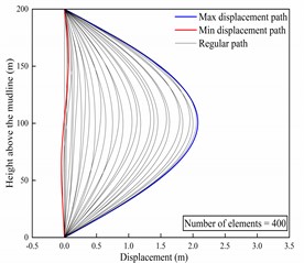
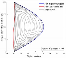
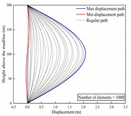
Configuring the length of the riser to be 200 meters, calculation time to be 30 seconds, and time step to be one second. Setting the number of riser elements to 400, 800, and 1000, the in-line displacement envelopes of the riser were computed for these scenarios. The computed results are depicted in Fig. 4. From Fig. 4, it can be observed that the displacement envelopes for the three scenarios are quite consistent. Furthermore, the curves for maximum displacement and minimum displacement are the same across all three cases. Moreover, specific computed results are displayed in Table 2. It is evident that the displacement results are consistent across scenarios. Therefore, the mesh independence of this model is reliable. Hence, in order to ensure the accuracy and efficiency of the calculations, a riser model with 800 elements will be chosen for the subsequent computational analysis.
Table 2Specific numerical results of riser displacement
Number of elements | Max displacement (m) | Min displacement (m) | Regular displacement (m) (Height = 100 m, time = 20 s) | Regular displacement (m) (Height = 150 m, Time = 15 s) |
400 | 2.0787 | –0.0466 | 0.2660 | 0.5362 |
800 | 2.0785 | –0.0468 | 0.2679 | 0.5370 |
1000 | 2.0786 | –0.0468 | 0.2681 | 0.5369 |
Fig. 4In-line displacement envelope of riser
a)
b)
c)
4.2. Time domain dynamic response of riser
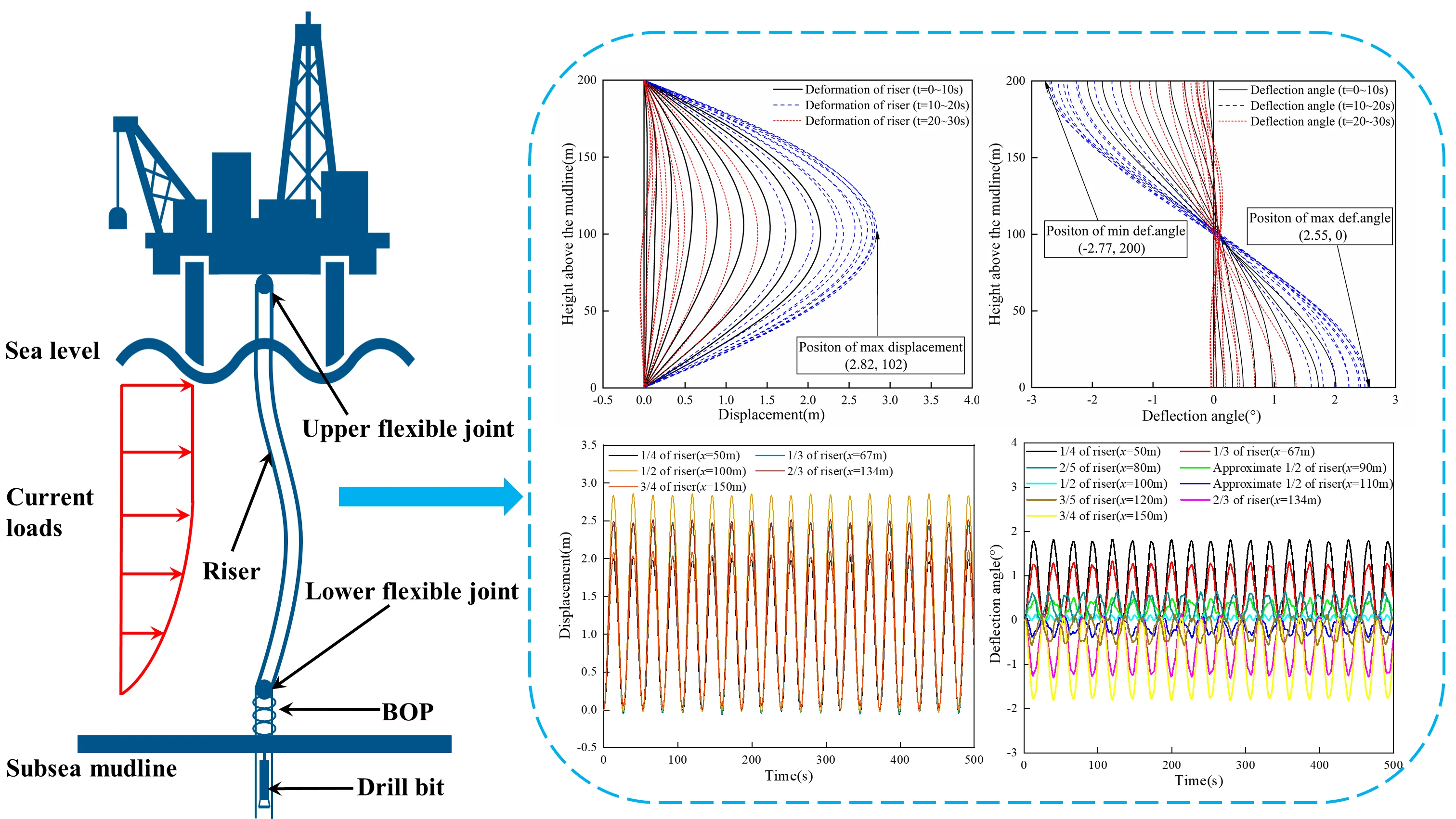
The variations in the displacement and deflection angle of the riser are illustrated in Fig. 5. The curves in the figure, represented by different colors, depict the variation of deformation and deflection angles of the riser within different time intervals (0-10 s, 10-20 s, 20-30 s). As can be seen from Fig. 5, it is evident that the maximum displacement occurs at the midpoint of the riser (102 m) with a magnitude of 2.82 m. In addition, there are instances of “reverse offset” observed in the riser at certain times. The diagram also indicates that the riser undergoes deflection at different positions, with the deflection angle near the middle of the riser being approximately zero. The deflection angle demonstrates symmetrical behavior with respect to the midpoint of the riser, exhibiting a maximum angle of 2.55° and a minimum angle of –2.77°.
In order to provide a more comprehensive representation of the dynamic response of the riser, the calculation time has been set to 500 seconds. The displacement responses of the five positions along the riser are presented in Fig. 6. Observing the results, it is evident that the riser's displacement undergoes periodic changes with a response period of approximately 27 seconds. Upon closer inspection, it is apparent that the displacement of the riser at the 2/3 mark surpasses the displacement at the 1/3 mark. Likewise, the displacement at the 3/4 mark exceeds that at the 1/4 mark. These observations indicate that the riser's displacement is not perfectly symmetric around its middle section. Specifically, among the two positions symmetric about the midpoint of the riser, the one at a greater water depth experiences a larger displacement.
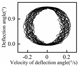
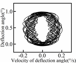
The response of the deflection angle at various positions of the riser is presented in Fig. 7, including a central section (100 m) and four symmetrical groups of positions. It is evident from Fig. 7 that the deflection angle increases as the position moves closer to the end of the riser. Conversely, as the position approaches the middle of the riser, the deflection angle gradually decreases and eventually approaches zero. In addition, the periodicity of the deflection angle response varies with the position of the riser. The central section exhibits a higher degree of periodicity, while the degree of periodicity gradually decreases towards both ends of the riser. The deflection angle response shows quasi-periodic variations (including transient instabilities) with the waveform differing slightly from one cycle to another, rather than purely periodic behavior (steady-state behavior). The phase diagram for each position of the riser is displayed in Fig. 8. From the results depicted in Fig. 8, it can be observed that the periodicity of the deflection angle response decreases from the middle to both ends of the riser and then increases again.
Fig. 5In-line displacement and deflection angle of riser
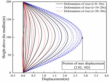
a) Displacement envelope

b) Deflection angle envelope
Fig. 6Displacement response of the riser
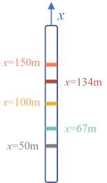
a) Riser markings
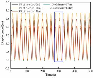
b) Displacement curve
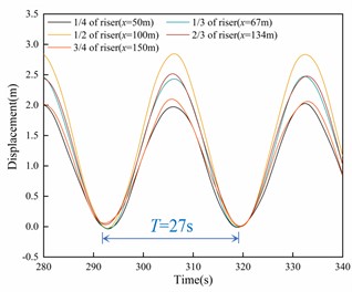
c) Enlarged view
Fig. 7Deflection angle response of riser
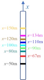
a) Riser markings
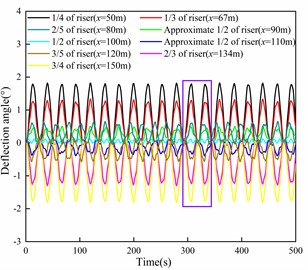
b) Deflection angle curve
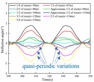
c) Enlarged view
Fig. 8Deflection angle phase diagram of riser
a)50 m
b) 67 m
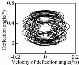
c)80 m
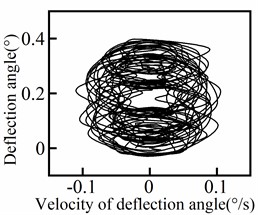
d) 90 m
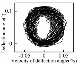
e) 100 m
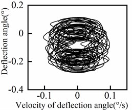
f)110 m
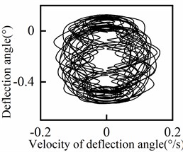
g)120 m
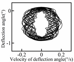
h)134 m
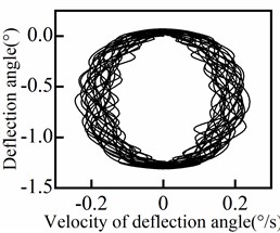
i) 150 m
4.3. Analysis of parameter sensitivity
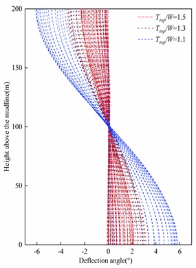
The effect of top tension, sea surface tidal current velocity, wave period, and wave height on riser deformation was analyzed while keeping the riser parameters and ocean parameters constant. Specifically, the influence of top tension on riser deformation was examined, as depicted in Fig. 9. It is evident that the in-line displacement and deflection angle amplitude of the riser decrease with increasing top tension. This indicates that increasing the top tension effectively restrains the deformation of the riser. The underlying reason for this phenomenon is that augmenting the top tension is equivalent to enhancing the bending stiffness of the riser, thereby reducing its deformation.
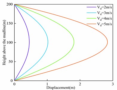
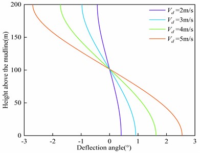
The relationship between sea surface tidal current velocity and the maximum displacement as well as the maximum deflection angle of the riser is depicted in Fig. 10. It is observed that both the maximum offset and the maximum deflection angle of the riser increase with higher sea surface tidal current velocities. Furthermore, as the sea surface current velocity increases, the rate of increment in displacement and deflection angle also increases. It can be inferred that the impact of sea surface tidal current velocity on riser deformation is nonlinear. The underlying reason for this behavior is that the external load acting on the riser is related to the square term of the sea surface tidal current velocity.
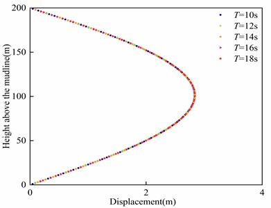
The influence of the wave period on riser is depicted in Fig. 11. It can be observed that the displacement and deflection angle of riser remain nearly constant regardless of the variation in wave period. Thus, the wave period has negligible influence on the deformation of the riser. Similarly, the effect of wave height on riser deformation is illustrated in Fig. 12. It can be noted that the riser deformation remains relatively unchanged as the wave height varies, indicating that wave height also has minimal impact on riser deformation.
Fig. 9Influence of top tension on riser deformation
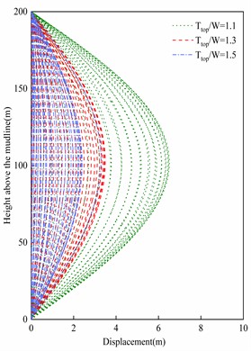
a) Displacement envelope
b) Deflection angle envelope
Fig. 10Influence of sea surface tidal current velocity on riser deformation
a) Maximum displacement
b) Maximum deflection angle
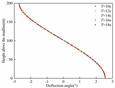
Fig. 11Influence of wave period on riser deformation
a) Maximum displacement
b) Maximum deflection angle
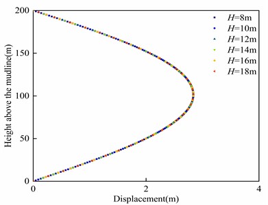
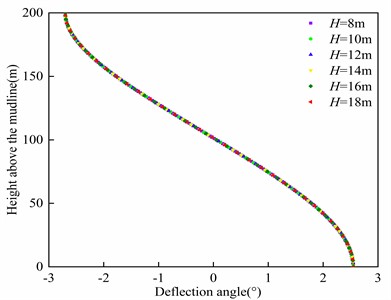
Fig. 12Influence of wave height on riser deformation
a) Maximum displacement
b) Maximum deflection angle
The frequency domain analysis of the system involves calculating the natural frequencies and conducting vibration mode analysis. Utilizing the previously obtained finite element model of the riser, the natural frequencies for each mode of the riser can be determined. Table 3 presents the first 10 natural frequencies of the system. It is evident that the first three natural frequencies of the riser are relatively low, indicating a higher susceptibility to resonance when subjected to external loads.
Table 3Natural frequency of riser
Order | Frequency (Hz) | Order | Frequency (Hz) |
1 | 0.0164 | 6 | 3.1313 |
2 | 0.2372 | 7 | 4.4342 |
3 | 0.6269 | 8 | 5.9731 |
4 | 1.2306 | 9 | 7.7482 |
5 | 2.0639 | 10 | 9.4615 |
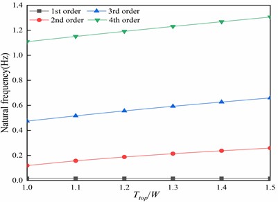
The impact of top tension on the natural frequency of the riser is depicted in Fig. 13. It is observed that, with the exception of the first-order natural frequency, the natural frequency of each mode increases as the top tension increases. It can be inferred that increasing the top tension can enhance the natural frequency of the riser and diminish the likelihood of resonance occurrences.
Fig. 13Influence of top tension on natural frequency of riser
5. Conclusions
In this paper, a nonlinear ocean current load model is established based on the Morrison equation, and the differential equation of the riser system under nonlinear ocean current load is derived by applying the principle of minimum potential energy. Subsequently, the differential equation is discretized into a finite element model using the cubic Hermite interpolation function and the Galerkin weighted residual method. The dynamic response of the riser is obtained using the Newmark numerical integration method. Based on the analysis, the following conclusions are drawn:
1) According to the numerical results, it is observed that the maximum in-line displacement is located in the middle of the riser, while the maximum deflection angle occurs at the end of the riser. Additionally, there are instances where the riser exhibits a phenomenon known as “reverse offset”, and the deflection angle shows symmetry about the center point of the riser.
2) The periodicity of the riser deflection angle response varies depending on the position along the riser. Specifically, the periodicity of the deflection angle response from the middle to both ends of the riser exhibits a decreasing trend followed by an increasing trend. Furthermore, the deflection angle response in the middle section of the riser exhibits the highest degree of periodicity.
3) The riser is highly sensitive to the top tension, as it has a significant impact on its behavior. With an increase in top tension, both the maximum displacement and maximum deflection angle of the riser decrease, while the natural frequency increases. This can be attributed to the fact that increasing the top tension suppresses the deformation of the riser by enhancing its bending stiffness.
4) Among the various ocean parameters considered, it is noteworthy that only the sea surface tidal current velocity exhibits a significant impact on riser deformation. The displacement and deflection angle of the riser demonstrate an increasing trend as the sea surface tidal current velocity rises. It is important to note that the influence of sea surface tidal current velocity on riser deformation follows a non-linear pattern. Conversely, parameters such as wave period and wave height have negligible effects on the behavior of the riser.
The findings of this study contribute to the understanding of the motion characteristics and parameter sensitivities of risers in complex marine environments. and a theoretical foundation is established for the assessment of riser reliability and determination of operational parameters in actual marine environments.
References
-
B. G. Burke, “An analysis of marine risers for deep water,” Journal of Petroleum Technology, Vol. 26, No. 4, pp. 455–465, Apr. 1974, https://doi.org/10.2118/4443-pa
-
C. P. Sparks, “Mechanical behavior of marine risers mode of influence of principal parameters,” Journal of Energy Resources Technology, Vol. 102, No. 4, pp. 214–222, Dec. 1980, https://doi.org/10.1115/1.3227875
-
M. Liao, G. Wang, Z. Gao, Y. Zhao, and R. Li, “Mathematical modelling and dynamic analysis of an offshore drilling riser,” Shock and Vibration, Vol. 2020, pp. 1–13, Aug. 2020, https://doi.org/10.1155/2020/8834011
-
G. Gao, X. Qiu, K. Wang, and J. Liu, “Nonlinear quasi-static analysis of ultra-deep-water top-tension riser,” IOP Conference Series: Materials Science and Engineering, Vol. 231, No. 1, p. 012068, Sep. 2017, https://doi.org/10.1088/1757-899x/231/1/012068
-
M. M. Bernitsas, J. E. Kokarakis, and A. Imron, “Large deformation three-dimensional static analysis of deep water marine risers,” Applied Ocean Research, Vol. 7, No. 4, pp. 178–187, Oct. 1985, https://doi.org/10.1016/0141-1187(85)90024-0
-
M. M. Bernitsas and N. Vlahopoulos, “Static non‐linear three‐dimensional analysis of a riser bundle by a substructuring and incremental finite element algorithm,” International Journal for Numerical Methods in Engineering, Vol. 28, No. 11, pp. 2517–2540, Nov. 1989, https://doi.org/10.1002/nme.1620281104
-
C. L. Kirk, E. U. Etok, and M. T. Cooper, “Dynamic and static analysis of a marine riser,” Applied Ocean Research, Vol. 1, No. 3, pp. 125–135, Jul. 1979, https://doi.org/10.1016/0141-1187(79)90012-9
-
S. Lei, X. Y. Zheng, and D. Kennedy, “Dynamic response of a deepwater riser subjected to combined axial and transverse excitation by the nonlinear coupled model,” International Journal of Non-Linear Mechanics, Vol. 97, pp. 68–77, Dec. 2017, https://doi.org/10.1016/j.ijnonlinmec.2017.09.001
-
J. Duan, J. Zhou, Y. You, and X. Wang, “Time-domain analysis of vortex-induced vibration of a flexible mining riser transporting flow with various velocities and densities,” Ocean Engineering, Vol. 220, p. 108427, Jan. 2021, https://doi.org/10.1016/j.oceaneng.2020.108427
-
F. Wang, W. Xiao, Y. Yao, Q. Liu, and C. Li, “An analytical procedure to predict transverse vibration response of jack-up riser under the random wave load,” Shock and Vibration, Vol. 2020, No. 1, pp. 1–9, Jun. 2020, https://doi.org/10.1155/2020/5072989
-
D. Yin et al., “Experimental and numerical study of a top tensioned riser subjected to vessel motion,” Ocean Engineering, Vol. 171, pp. 565–574, Jan. 2019, https://doi.org/10.1016/j.oceaneng.2018.12.029
-
Z. Kang, L. Q. Hung, S. Li, R. Chang, and H. Sui, “Numerical and experimental study on the dynamics of the tendon/top tension riser system of a tension-leg platform,” Journal of Marine Science and Application, Vol. 21, No. 4, pp. 177–191, Dec. 2022, https://doi.org/10.1007/s11804-022-00309-3
-
D. Liu, S. Ai, L. Sun, J. Wei, and N. He, “Numerical modelling of offshore risers conveying slug flow under the ALE-ANCF framework,” Ocean Engineering, Vol. 235, p. 109415, Sep. 2021, https://doi.org/10.1016/j.oceaneng.2021.109415
-
G. Liu, H. Li, Y. Xie, A. Incecik, and Z. Li, “Investigating cross-flow vortex-induced vibration of top tension risers with different aspect ratios,” Ocean Engineering, Vol. 221, p. 108497, Feb. 2021, https://doi.org/10.1016/j.oceaneng.2020.108497
-
Y. Yuan, H. Xue, and W. Tang, “Internal laminar flow effect on the nonlinear dynamic response of marine risers under uniform ocean current,” Ships and Offshore Structures, Vol. 17, No. 6, pp. 1382–1391, Jun. 2022, https://doi.org/10.1080/17445302.2021.1924494
-
H. Guo, L. Zhang, X. Li, and M. Lou, “Dynamic responses of top tensioned riser under combined excitation of internal solitary wave, surface wave and vessel motion,” Journal of Ocean University of China, Vol. 12, No. 1, pp. 6–12, Mar. 2013, https://doi.org/10.1007/s11802-013-2079-y
-
M. Lou, C. Yu, and P. Chen, “Dynamic response of a riser under excitation of internal waves,” Journal of Ocean University of China, Vol. 14, No. 6, pp. 982–988, Dec. 2015, https://doi.org/10.1007/s11802-015-2701-2
-
X. Liu et al., “Improved axial dynamic analysis of risers based on finite element method and data-driven models,” Ocean Engineering, Vol. 214, No. 14, p. 107782, Oct. 2020, https://doi.org/10.1016/j.oceaneng.2020.107782
-
J. Du Kim, B.-S. Jang, and R.-H. Yun, “Application of analytical model in the prediction of dynamic responses and fatigue damage of flexible risers: Part I – Improvement of analytical model considering shear deformation and varying tension effects,” Marine Structures, Vol. 79, p. 103044, Sep. 2021, https://doi.org/10.1016/j.marstruc.2021.103044
-
W. Xie, W. Xin, and H. Zhang, “Influence of the internal varying density flow on the vibrations and fatigue damage of a top-tensioned riser undergoing vortex-induced vibrations,” Applied Ocean Research, Vol. 117, p. 102955, Dec. 2021, https://doi.org/10.1016/j.apor.2021.102955
-
H. Jeong, B.-S. Jang, J. Du Kim, G. Park, J. Choi, and D. Lee, “A study on effects of slug flow on dynamic response and fatigue damage of risers,” Ocean Engineering, Vol. 217, No. 17, p. 107965, Dec. 2020, https://doi.org/10.1016/j.oceaneng.2020.107965
-
J. Du Kim, B.-S. Jang, and R.-H. Yun, “Application of analytical model in the prediction of dynamic responses and fatigue damage of flexible risers: Part II – Dynamic analysis of flexible risers in large-scale domain using a direct moment correction method,” Marine Structures, Vol. 79, p. 103051, Sep. 2021, https://doi.org/10.1016/j.marstruc.2021.103051
-
M. H. Patel, S. Sarohia, and K. F. Ng, “Finite-element analysis of the marine riser,” Engineering Structures, Vol. 6, No. 3, pp. 175–184, Jul. 1984, https://doi.org/10.1016/0141-0296(84)90045-2
-
J. F. Mcnamara, P. J. O. ’Brien, and S. G. Gilroy, “Nonlinear analysis of flexible risers using hybrid finite elements,” Journal of Offshore Mechanics and Arctic Engineering, Vol. 110, No. 3, pp. 197–204, Aug. 1988, https://doi.org/10.1115/1.3257051
-
G. W. Wang, M. L. Liao, and H. W. Jiang, “Dynamics of marine risers under the action of return-flow of drilling fluid,” Journal of Ship Mechanics, Vol. 27, No. 5, pp. 719–730, 2023, https://doi.org/10.3969/j.issn.1007-7294.2023.05.011
About this article

The authors would like to express their sincere gratitude to Mr. Li and Mr. Zhang for their invaluable contributions in the collection of field data. Their dedicated efforts and expertise in gathering and organizing the necessary data have been essential for the successful completion of this research. Additionally, the authors would like to extend their appreciation to Mr. Wang and Mr. Sun for their diligent analysis of the simulated data. Their insightful inputs and meticulous examination have greatly enhanced the quality and reliability of the findings presented in this paper. The authors would also like to acknowledge the support and guidance provided by Hainan Branch of CNOOC (China) Co., Ltd throughout the duration of this study.
The datasets generated during and/or analyzed during the current study are available from the corresponding author on reasonable request.
Huakui Xu collected field parameter data and conducted literature research on the hydrodynamic problems of risers. Shaoping Yuan derived the hydrodynamic model for the riser and provided financial support. Heng Luo utilized the theoretical results to develop a numerical simulation program in Matlab. Kexin Wang performed numerical analysis on the simulated data. Pan Fang provided theoretical guidance for this topic.
The authors declare that they have no conflict of interest.
