Abstract
To reduce the errors caused by the rigid body hypothesis in the aerodynamics-structure coupling calculation and improve the structural performance, an optimum structure design with the consideration of the fluid-structure interaction are performed for the H-type vertical axis wind turbine (VAWT) blade. Based on the ANSYS Workbench platform, the geometric model, computational domain and grids of the wind wheel are constructed, the turbulence model, boundary conditions and composite material layers are set up, and the fluid and solid domains are solved in a coupled way. The single-objective structural optimization model in which the thicknesses of glass clothes, foam and gel coat, and the positions of two webs are taken as design variables is solved using the response surface optimization method to minimize the wind wheel mass. The frequencies and vibration modes of original and optimized blades with and without pre-stress and the transient characteristics of wind wheels in different wind speeds are investigated. The results indicate that after the blade optimization, the first-order frequency and critical speed become larger and other frequencies reduce for the static, single pre-stress and multiple pre-stresses states, and the maximum displacement, stress and strain of the wind wheel decrease under rated and extreme wind speeds, confirming significant performance improvements. The research provides useful guidance for the integrated design of structure and aerodynamics of wind turbine blades.
Highlights
- An optimum structure design are performed for VAWT blade.
- The results confirm significant performance improvements.
- The research provides useful guidance for the integrated design of structure and aerodynamics.
1. Introduction
The aerodynamic load and structural deformation change all the time for wind turbine blades during operation, and the interaction between flow field and structure easily leads to the aero-elastic coupling vibration, stall flutter and even fracture failure [1, 2]. Hence, much effort is usually spent on the optimization of composite material layers and structure geometry parameters of the blade with the consideration of fluid-structure interaction to effectively reduce the fatigue damage and extend the working life. Bedon et al. [3] conducted the aero-structural optimization design of Darrieus VAWT based on the Blade Element-Momentum algorithm, Euler-Bernoulli Beam theory and Genetic Algorithm (GA). Kim et al. [4] carried out the topological optimization for the inner support structure of 5 MW horizontal axis wind turbine (HAWT) blade in the fluid-structure coupled case. Chen et al. [5] combined the aero-elastic coupling analysis method with improved GA to optimize the single-layer thickness of composite material and the position of main beam for HAWT blade. Zheng et al. [6] optimized the twist angle, chord length and layer thickness of HAWT blade using GA while considering the interaction between elastic deformation and flow field. Wang et al. [7] performed the multi-objective structure-aerodynamics integration optimization of 1.5 MW HAWT blade by a high-performance evolutionary algorithm combined with an ultimate load calculation method.
The structural performance of the blade is also investigated under fluid-structure interaction considerations. Bazilevs et al. [8, 9] conducted the structural discretization and full-size fluid-structure interaction calculation of 5 MW HAWT blade. Lee et al. [10] analyzed the displacement and torsion angle with time for different sections of HAWT blade considering the fluid-structure interaction. Halawa et al. [11], Dose et al. [12] and Borouji et al. [13] studied the structural deformation, thrust and output power of 5 KW HAWT using the fluid-structure interaction simulation. Yu et al. [14] used the CFD-CSD loose coupling method to calculate the elastic deformation of HAWT blade. Li et al. [15] simulated the fluid-structure interaction of HAWT rotor under the shear inflow condition. Yao et al. [16] and Dai et al. [17] carried out the fluid-structure interaction calculation of Tjaereborg HAWT blade. Mo et al. [18] obtained the node displacements of small-scale VAWT in fluid-structure interaction conditions using the COMSOL Mutiphysics software. Lv et al. [19] and Liao et al. [20] applied the zonal weak coupling method to establish the nonlinear fluid-structure interaction model of HAWT blade, and analyzed the natural frequency and unsteady response.
Taken together, the above researches mainly focused on HAWT. The structural optimization of VAWT blade taking the interaction between structural deformation and fluid movement into account has been rarely reported, even though the VAWT has the advantages of good aerodynamic performance, simple structure, easy installation and maintenance, and low noise. Hence, the present study firstly introduces the two-way fluid-structure interaction calculation on the ANSYS Workbench platform. Then, the response surface optimization method is applied to optimize the material layer and inner structure of VAWT blade. Finally, the vibration modal of the blade for various pre-stress states and the transient response of the wind wheel under rated and extreme wind speeds are analyzed.
2. Two-way fluid-structure interaction analysis method and adaptability validation
Based on the ANSYS Workbench platform, the geometric model and computational domain are generated in the DesignModeler module, the composite material lay-up is conducted in the ACP (Pre) module suppressing the computational domain, the transient analysis is set up in the Transient Structural module, the solving settings of the computational domain are completed in the Fluid Flow (Fluent) module suppressing the solid domain, and the coupled calculation of fluid and solid domains is realized in the System Coupling module. To show the applicability of this method, the rotating aircraft aileron analyzed by Fluid Flow (CFX) in Ref. [21] is studied. The mesh divisions and boundary conditions in fluid and solid domains and the solution time and time step in the Transient Structural module are the same as those of Ref. [21]. The geometric model, computational domain and grids are shown in Fig. 1 for the stationary wing and moving aileron. In the Fluid Flow (Fluent) module, the Realizable - turbulence model, SIMPLE algorithm, and diffusion smoothing integrated with remeshing are adopted, and the inlet velocity is 1 m/s. In the System Coupling module, the fluid-structure interaction solution time is 1 s.
Fig. 1Geometric model, calculational domain and grids of the wing and aileron
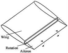
a) Geometric model
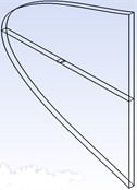
b) Computational domain
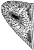
c) Grids
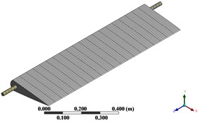
d) Local grids
Fig. 2 gives the surface pressures at 0.1 s and 0.2 s for the section of 0.5 m. The pressure coefficients are approximately equal to those form Ref. [21] at most positions. The Fluent software adopts the finite volume method, while the CFX software adopts the finite element-based finite volume method, resulting in the differences at a few coordinate points. Moreover, the CFX with limited grid processing capability is only applicable to calculate the small structural deformation, and the computer memory occupied and single-step calculation time are more than those in Fluent. The fluid-structure interaction analysis of the wind wheel involves the large deformation and the reconstruction and update of the grid, thus the method in this paper is more suitable.
Fig. 2Pressure coefficients at different moments for the aileron section
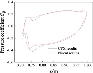
a) 0.1 s
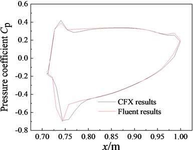
b) 0.2 s
3. Structural optimization of the blade under fluid-structure interaction conditions
3.1. Optimization model
The strength ratio of the small-scale VAWT blade is much less than 1 at the rated wind speed, confirming that the facture failure will not occur. Thus, the optimal objective is to minimize the wind wheel mass:
where is the vector of optimal variables, and is the wind wheel mass.
The optimal variables include the thicknesses of uniaxial glass cloth, biaxial glass cloth, triaxial glass cloth, foam and gel coat, and the positions of two webs. Table 1 lists their initial values and ranges:
Table 1Initial values and ranges of optimal variables
Optimal variables | Initial values (with c the chord length) | Ranges |
Thickness of uniaxial glass cloth / mm | 0.5 | 0.4-0.55 |
Thickness of biaxial glass cloth / mm | 0.5 | 0.4-0.55 |
Thickness of triaxial glass cloth / mm | 0.35 | 0.28-0.385 |
Thickness of the foam / mm | 2 | 1.2-2.2 |
Thickness of the gel coat / mm | 0.25 | 0.2-0.275 |
Position of the web near the leading-edge / m | 0.2c | 0.15-0.25 |
Position of the web near the trailing-edge / m | 0.5c | 0.5-0.6 |
The maximum stress , maximum strain and maximum deformation of the wind wheel after the structural optimization should be smaller than the initial maximum stress , initial maximum strain and initial maximum deformation , respectively. Thus, the optimal variables are bounded by:
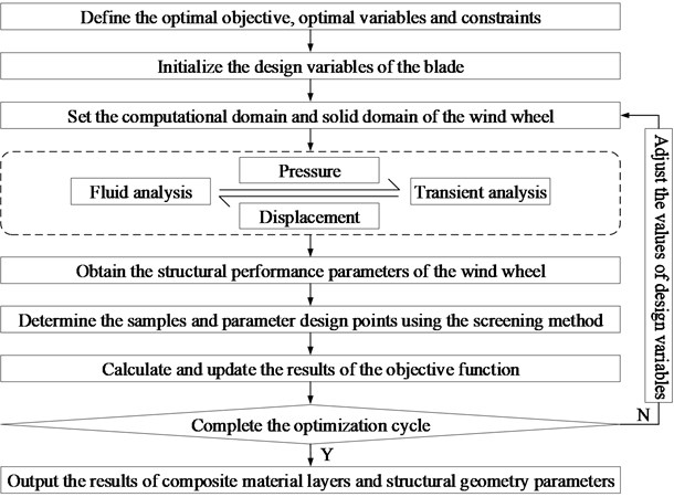
The Design Exploration is a rapid optimization tool of ANSYS Workbench, and its response surface optimization project classified as the goal-driven optimization can accurately describe the relationship between input and output parameters and has the advantages of short calculation time and high efficiency. The blade’s structural optimization process adopting the response surface optimization is shown in Fig. 3.
Fig. 3Flow chart of the blade’s structural optimization
3.2. Optimization example
An H-type VAWT blade from Ref. 22 is chosen as a testbed. As for the basic parameters, the rated wind speed is 7 m/s, the rated power is 100 W, the rated speed is 200 r/min, the blade number is 3, the tip speed ratio is 1.777, the rotation diameter of the wind wheel is 1.1889291 m, the blade length is 1.307822023 m, and the chord length of NACA0021SC airfoil is 0.313503278 m. The fluid-structure interaction calculation process of the wind wheel is shown in Fig. 4. During the optimization, the type of the response surface is the genetic aggregation, the screening method is adopted, the quantity and starting point number of the initial sample are 100 and 5, and the optimization iteration is 81.
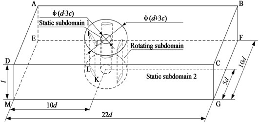
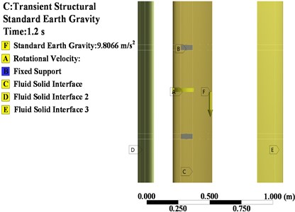
In the DesignModeler module, the airfoil profile formed by the 3D Curve command stretches symmetrically with the size of 0.5 to obtain the solid model of the blade. Two web planes established through offsetting the plane along the -axis by 0.2 and 0.5 are taken as the boundaries, and the blade is divided into three parts using the Slice command. The solid model of the wind wheel is shown in Fig. 5 by translating and arraying the three parts. A cuboid of size and two cylinders with the height of and diameters of and are established, and their attributes are Fluid. Through using the Boolean subtraction retain subtracted parts, the computational domain consisting of two static subdomains and one rotating subdomain is obtained, as shown in Fig. 6. The thicknesses of the leading-edge, main beam, trailing-edge and webs are defined to be 0 by the Thin/Surface command. The left and right surfaces of the computational domain constitute the velocity inlet and pressure outlet, respectively. The moving and adiabatic wall boundary conditions are applied on three blades, namely blade 1, blade 2 and blade3. The connection between static and rotating subdomains adopts the interface boundary, and the upper and lower surfaces of the rotating subdomain are represented by rotating-wall1 and rotating-wall2.
Fig. 4Flow chart of the fluid-structure interaction calculation of the wind wheel
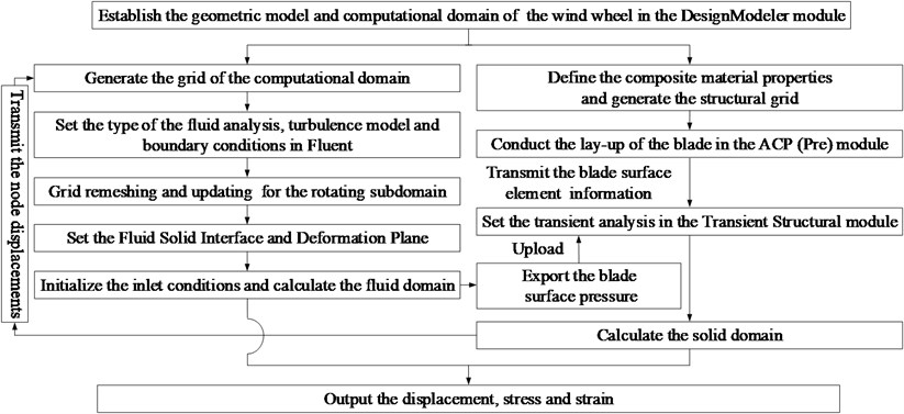
Fig. 5Solid model of the wind wheel
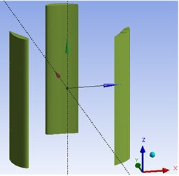
Fig. 6Computational domain of the wind wheel
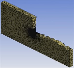
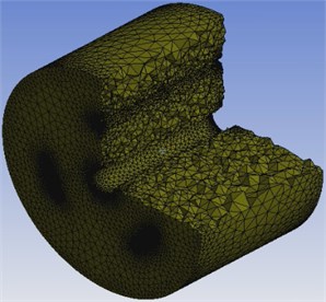
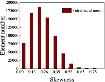
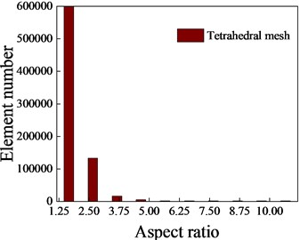
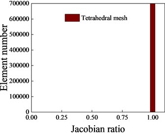
In the Fluid Flow (Fluent) module, the fluid domain is discretized by an unstructured tetrahedral grid. The airfoil profile and the inner and outer circumferences of the computational domain are evenly divided according to the element sizes of 0.002 m, 0.008 m and 0.04 m, respectively. The edges IL and JK are evenly divided into 25 parts, and AB, BC, CD and DA are uniformly divided according to the element size of 0.07 m. The volume grids consist of 147637 nodes and 746667 elements, as shown in Fig. 7. Moreover, Fig. 8 gives the skewness, aspect ratio and Jacobian ratio of the grids through changing the mesh measurement in Mechanical. The skewness mainly ranges from 0 to 0.6, and its maximum value is 0.84 and less than 0.97. The aspect ratio is mainly around 1.6 and 2.6, and the Jacobian ratio is concentrated nearby 1. These indicate that the grid quality is good, avoiding the negative volume that can lead to the failure of the aerodynamic performance calculation.
The dynamic mesh combining the diffusion smoothing with remeshing is more suitable for a rotating wind wheel. The diffusion parameter is 1.5, and the maximum and minimum element sizes in the remeshing are 1.5 times and half those of the maximum and minimum grids generated, respectively. The skewness of the surface mesh is 0.7, and so is 0.9 for the volume mesh. The surfaces of blade1, blade2 and blade3 are defined as the Fluid Solid Interface, and the rotating-wall1 and rotating-wall2 are the Deformation Plane.
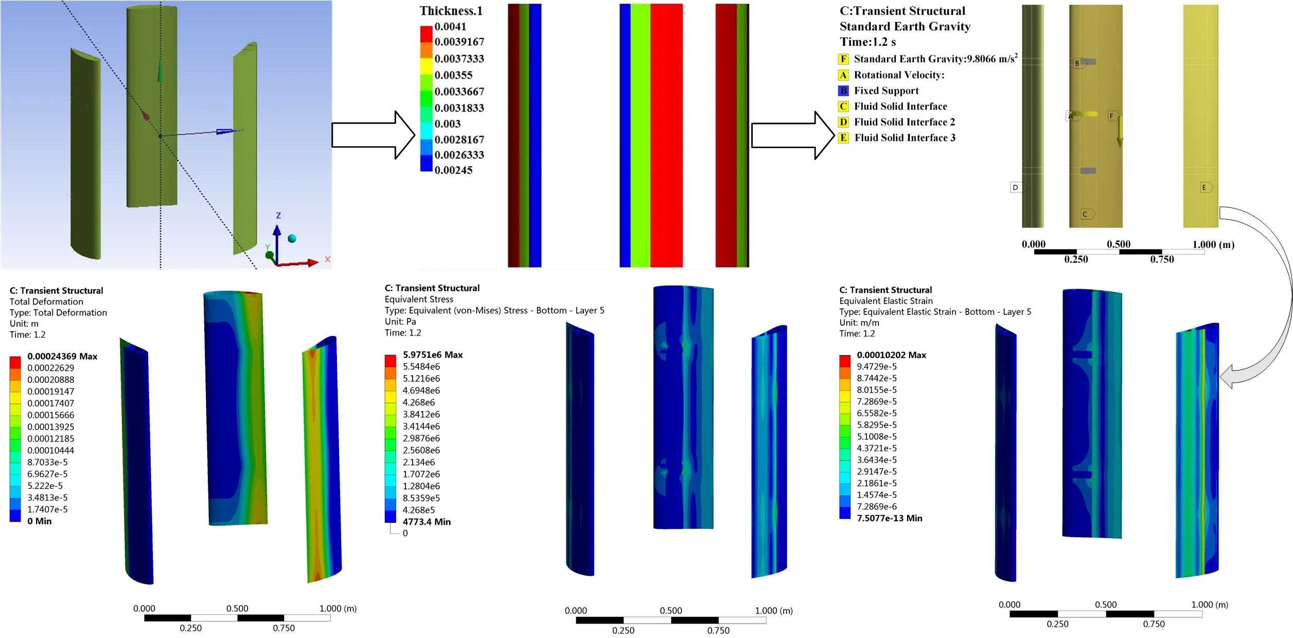
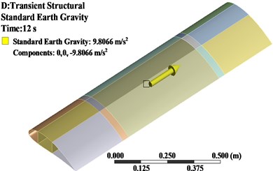
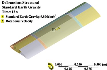
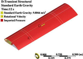
The geometric model and computational domain of the wind wheel are imported into the ACP (Pre) module. The blade surfaces are discretized using the quadrilateral grid with the element size of 0.02 m to obtain the surface grids with 7760 nodes and 8050 elements. The ply materials, layer number and reference coordinate system are set according to Ref. [23]. The initial stacking sequences and numbers of the leading-edge, main beam, trailing-edge and webs are FM+TM+3UM+TM, FM+TM+BM+3UM+BM+TM, FM+TM+3UM+GM and 2BM+GM+2BM (with UM, BM, TM, FM and GM for the uniaxial glass cloth, biaxial glass cloth, triaxial glass cloth, foam and gel coat), respectively, and the ply angle is 0°, as shown in Fig. 9. The layer information is transferred to the Transient Structural module, the gravitational acceleration and angular velocity around the -axis counterclockwise are applied, and the node displacements are restrained for the parts that the blades are in contact with the arms, as shown in Fig. 10. The Weak Springs is turned off, the Large Deflection is turned on, and the displacement, stress and strain are output.
Fig. 7Grids of the computational domain
a) Sectional view of the computational domain
b) Sectional view of the rotating subdomain
Fig. 8Grid quality parameters
a) Skewness
b) Aspect ratio
c) Jacobian ratio
Fig. 9Blades with initial composite material layers
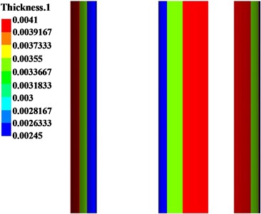
Fig. 10Constrained wind wheel
In the System Coupling module, the analysis time is 1.2 s and the time step is 0.0015 s. It can be seen from Fig. 11 that the maximum displacement and stress fluctuate greatly in the early stage, indicating that the aerodynamic load calculated in the fluid domain also changes obviously, and their fluctuations gradually become smaller with time. The structure tends to be stable near 0.3 s under the influence of the flow field. So the displacement, stress and strain after 0.3 s are extracted, reflecting the structural performance during operation more accurately.
Fig. 11Maximum displacement and stress of the wind wheel at different moments
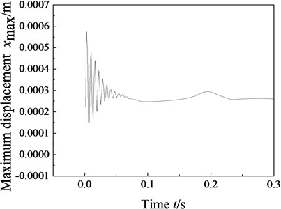
a) Maximum displacement
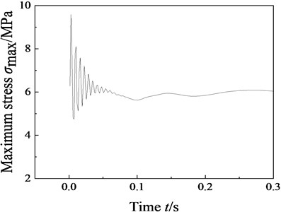
b) Maximum stress
Table 2 gives the optimization results of composite material layers and inner structure parameters. The optimized wind wheel mass is 7.0075 kg and decreases by 6.57 % compared with the original structure mass 7.5 kg.
Table 2Optimization results of the blade
Optimal variables | / mm | / mm | / mm | / mm | / mm | / m | / m |
Values | 0.4353 | 0.5274 | 0.3086 | 2.15 | 0.2177 | 0.1618c | 0.5147c |
4. Effects of the structural optimization on modal and transient characteristics
The continuous resonance can shorten the service life of wind turbine blades, and the long-term effect of the periodic aerodynamic force will lead to the fatigue failure. Hence, the modal analysis of the blade and the transient calculation of the wind wheel are carried out with an aim to study the effects of the blade’s structural optimization considering the fluid-structure interaction on the performance improvement.
4.1. Modal analysis
The forces acted on the blade for the static, single pre-stress and multiple pre-stresses states are shown in Fig. 12. Table 3 lists only the early six frequencies due to the greater influence of the lower frequencies on the stability of wind turbines. Under the static and single pre-stress states, the first-order frequencies and critical speeds increase and other frequencies decrease after the blade optimization. The first-order critical speeds are greater than 200 r/min that is 20 % of five times the rated speed, confirming that the resonance will not occur for the blade. The dynamic stiffening effect makes the frequencies under the single pre-stress state smaller than those under the static state. Under the multiple pre-stresses state, the frequencies and critical speed are the same as those under the static state, indicating that the effect of the centrifugal force on the frequency counteracts that of the aerodynamic force. Therefore, the vibration frequencies of the blade with the effect of gravity only are calculated to prevent the resonance.
Fig. 12Force diagrams of the blade under the static, single pre-stress and multiple pre-stresses states
a) Static state
b) Single pre-stress state
c) Multiple pre-stresses state
Table 3Frequencies of the blade before and after the optimization
Order | Frequency / Hz | |||
Static state | Single pre-stress state | Multiple pre-stresses state | ||
Before the optimization | First-order | 63.55 | 63.47 | 63.55 |
Second-order | 148.90 | 148.87 | 148.90 | |
Third-order | 201.43 | 201.40 | 201.43 | |
Fourth-order | 214.68 | 214.65 | 214.68 | |
Fifth-order | 268.06 | 268.03 | 268.06 | |
Sixth-order | 310.79 | 310.77 | 310.79 | |
After the optimization | First-order | 66.05 | 65.97 | 66.05 |
Second-order | 142.37 | 142.33 | 142.37 | |
Third-order | 191.85 | 191.82 | 191.85 | |
Fourth-order | 209.87 | 209.84 | 209.87 | |
Fifth-order | 254.08 | 254.06 | 254.08 | |
Sixth-order | 283.45 | 283.43 | 283.45 | |
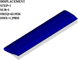
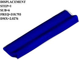
Fig. 13 only gives the mode shapes of the original blade under the static state since the original and optimized blades with and without pre-stress have the same mode shapes. The first-order mode shape is the first-order torsional vibration, the second-order mode shape is the first-order flapping and shimmy, the third- and fifth-order mode shapes are the second-order flapping and first-order shimmy, the fourth- and sixth-order mode shapes are the second-order torsional vibration and first-order shimmy, and the trailing-edge deformation is obvious along the span-wise.
Fig. 13Mode shapes of the original and optimized blades
a) First-order
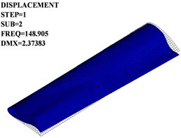
b) Second-order
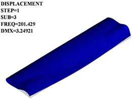
c) Third-order
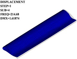
d) Fourth-order
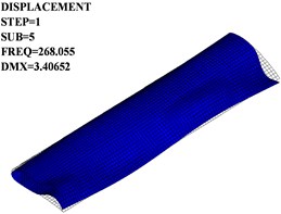
e) Fifth-order
f) Sixth-order
4.2. Transient analysis
Table 4 and Fig. 14 give the maximum values and distributions of the displacement, stress and strain for the original and optimized wind wheels under different wind speeds. In Table 4, the maximum displacement, stress and strain at the rated wind speed decrease by 2.00 %, 5.05 % and 23.77 % after the blade optimization, respectively, and so are 7.92 %, 6.16 % and 12.18 % at the extreme wind speed. The percentage decreases in the displacement and stress at the extreme wind speed are greater than those at the rated wind speed. In Fig. 14, the maximum displacement occurs at the trailing-edge of the blade, and the maximum stress and strain are at the blade-arm connections. These results indicate that the deformation- and damage- resistant capacities improve in comparison with the original wind wheel.
Table 4Maximum displacement, stress and strain of the original and optimized wind wheels
Structural performance | Rated wind speed | Extreme wind speed | ||
Original wind wheel | Optimized wind wheel | Original wind wheel | Optimized wind wheel | |
Maximum displacement / mm | 0.24867 | 0.24369 | 1.3365 | 1.2307 |
Maximum stress / MPa | 6.293 | 5.9751 | 15.825 | 14.85 |
Maximum strain | 0.13383 | 0.10202 | 0.51523 | 0.45247 |
Fig. 14Displacement, stress and strain distributions of the original and optimized wind wheels
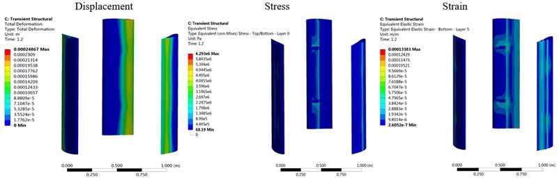
a) Original wind wheel at the rated wind speed
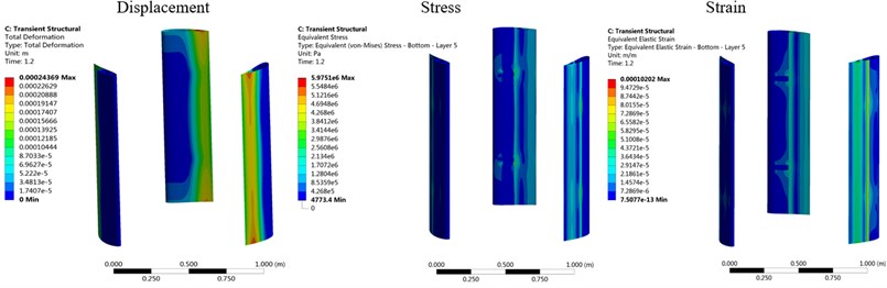
b) Optimized wind wheel at the rated wind speed
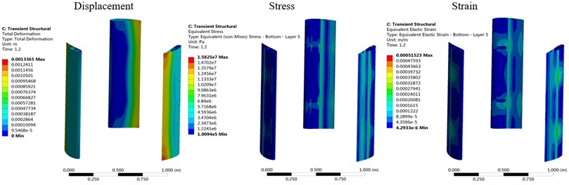
c) Original wind wheel at the extreme wind speed
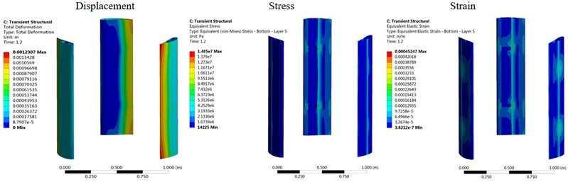
d) Optimized wind wheel at the extreme wind speed
5. Conclusions
Based on the ACP (Pre) module, Transient Structure module, Fluid Flow (fluent) module and System Coupling module of ANSYS Workbench, the composite material layer and inner structure of 100 W H-type VAWT blade are optimized under fluid-structure interaction conditions. For the original and optimized blades, the frequencies and mode shapes under the static state are the same as those under the multiple pre-stresses state, and the single pre-stress has slight effect on the modal parameters. After the blade optimization, the first-order critical speed increases and is greater than 20 % of five times the rated speed for various pre-stress states, indicating that the blade resonance will not occur. The maximum displacement, stress and strain decrease by as much as 2.00 %, 5.05 % and 23.77 % at the rated wind speed and 7.92 %, 6.16 % and 12.18 % at the extreme wind speed, weakening the stress concentration and deformation and increasing the strength thus significantly improving the structural performance.
References
-
Gilberto S., Mathijs P., Wim V. P., Joris D. Fluid-structure interaction simulations of a wind gust impacting on the blades of a large Horizontal Axis Wind Turbine. Energies, Vol. 13, Issue 3, 2020, p. 509-528.
-
Zhu J., Ni X. H., Shen X. M. Aerodynamic and structural optimization of wind turbine blade with static aeroelastic effects. International Journal of Low-Carbon Technologies, Vol. 15, Issue 1, 2020, p. 55-64.
-
Bedon G., Benini E. Aero-structural design optimization of vertical axis wind turbines. Wind Energy, Vol. 20, Issue 3, 2017, p. 491-505.
-
Kim D. H., Lim O. K., Choi E. H., Noh Y. Optimization of 5-MW wind turbine blade using fluid structure interaction analysis. Journal of Mechanical Science and Technology, Vol. 31, Issue 2, 2017, p. 725-732.
-
Chen J., Li S. L., Shen W. Z., Guo X. F. Design of composite wind turbine blade with aeroelastic effect. Acta Energiae Solaris Sinica, Vol. 38, Issue 5, 2017, p. 1354-1360.
-
Zheng Y. Q., Zhao R. Z., Liu H. Research of aerodynamic and structural coupling optimization design for blade of large-scale wind turbine. Acta Energiae Solaris Sinica, Vol. 36, Issue 8, 2015, p. 1812-1817.
-
Wang T. G., Wang L., Zhong W., Xu B. F., Chen L. Large-scale wind turbine blade design and aerodynamic analysis. Chinese Science Bulletin, Vol. 57, Issue 5, 2012, p. 466-472.
-
Bazilevs Y., Hsu M. C., Akkerman I., Wright S., Takizawa K., Henicke B., Spielman T., Tezduyar T. E. 3D simulation of wind turbine rotors at full scale. Part I: Geometry modeling and aerodynamics. International Journal for Numerical Methods in Fluids, Vol. 65, Issues 1-3, 2011, p. 207-235.
-
Bazilevs Y., Hsu M. C., Kiendl J., Wuchner R., Bletzinger K. U. 3D simulation of wind turbine rotors at full scale. Part II: Fluid-structure interaction modeling with composite blades. International Journal for Numerical Methods in Fluids, Vol. 65, Issues 1-3, 2011, p. 236-253.
-
Lee Y. J., Jhan Y. T., Chung C. H. Fluid-structure interaction of FRP wind turbine blades under aerodynamic effect. Composites Part B-Engineering, Vol. 43, Issue 5, 2012, p. 2180-2191.
-
Halawa A. M., Sessarego M., Shen W. Z., Yoshida S. Numerical fluid-structure interaction study on the NREL 5MW HAWT. Journal of Physics: Conference series, 2018, p. 022026.
-
Dose B., Rahimi H., Herraez I., Stoevesandt B., Peinke J. Fluid-structure coupled computations of the NREL 5 MW wind turbine by means of CFD. Renewable energy, Vol. 129, 2018, p. 591-605.
-
Borouji E., Nishino T. Fluid structure interaction simulations of the NREL 5MW wind turbine-Part I: Aerodynamics and blockage effect. Journal of Offshore Mechanics and Arctic Engineering-Transactions of the ASME, Vol. 141, Issue 2, 2019, p. 021801.
-
Yu D. O., Kwon O. J. Predicting wind turbine blade loads and aeroelastic response using a coupled CFD-CSD method. Renewable Energy, Vol. 70, 2014, p. 184-196.
-
Li Y., Kang S., Zhao P., Wang J. L. Numerical simulation of fluid-structure coupling of 2.5 MW wind turbine rotor in various wind speeds of shear inflow. Journal of Engineering Thermophysics, Vol. 35, Issue 11, 2014, p. 2192-2196.
-
Yao S. G., Dai L. P., Kang S. Aerodynamic performance and fluid-structure coupling analysis of wind turbine blades. Journal of Engineering Thermophysics, Vol. 37, Issue 5, 2016, p. 988-992.
-
Dai L. P., Yao S. G., Wang X. D., Kang S. Fluid-structure interaction performance of wind turbine blade under yawed condition. Acta Energiae Solaris Sinica, Vol. 38, Issue 4, 2017, p. 945-950.
-
Mo Q. Y., Yan S. K., Shi J. J., Liu X. C. Fluid-structure coupling analysis of off-grid small vertical axis wind turbine. Machinery Design and Manufacture, Vol. 10, 2017, p. 164-167.
-
Lv P., Liao M. F., Yin X. J. A structural-aerodynamic coupling method for nonlinear aeroelastic response of large-scaled HAWT. Acta Energiae Solaris Sinica, Vol. 38, Issue 8, 2017, p. 2126-2135.
-
Liao M. F., Li Y., Wang Q. Y., Lv P. Study on fluid-structure interaction characteristic for large scaled wind turbine blade. Mechanical Science and Technology for Aerospace Engineering, Vol. 37, Issue 4, 2018, p. 493-500.
-
Song X. G. ANSYS Fluid Structure Coupling Analysis and Engineering Example. First Edition, China Water Conservancy and Hydropower Press, BeiJing, 2012.
-
Zhang X., Li Z. X., Yu X., Li W. Aerodynamic performance of trailing-edge modification of H-Type VAWT blade considering camber effect. International Journal of Aeronautical and Space Sciences, Vol. 21, Issue 3, 2020, p. 587-598.
-
Xu Y. Structure Optimization Design of 5KW H type Vertical Axis Wind Composite Turbine Blade. Nanjing University of Aeronautics and Astronautics, 2012.
Cited by
About this article

This work was supported by the National Natural Science Foundation of China (Grant No. 51805369) and the Science and Technology Planning Project of Tianjin (Grant No. 20YDTPJC00820).
