Abstract
In order to improve the adaptive range of airflow velocity, an airflow piezoelectric generator based on multi-harmonic excitation is proposed. The flow field characteristics are obtained by CFD method, the acoustic vibration characteristics and variation with velocity of the excitation frequency are studied. The result shows that periodic compression and expansion of air are presented and a standing wave is formed inside the resonator, which can provide stable excitation source. The excitation frequencies are distributed on the acoustic modes of the resonator and captured. With different velocity segment, the excitation frequencies are different, and frequency conversion is presented from the first-order to the third-order and from the third-order to the first-order. The conclusions verify the feasibility of the multi-harmonic excitation energy exchange scheme, which is helpful to improve the flow velocity adaptive range of the airflow-induced vibration piezoelectric generator.
Highlights
- The paper proposes an airflow piezoelectric generator based on multi-harmonic excitation, which can improve the adaptive range of airflow velocity.
- The stable excitation source is generated with periodic compression and expansion of air inside the resonator.
- The excitation frequencies are distributed on the acoustic modes of the resonator and captured.
- The frequency conversion is presented from the first-order to the third-order and from the third-order to the first-order.
1. Introduction
Wireless sensor node network has been widely used in aerospace, military construction, transportation, agriculture and other fields [1], but the power supply is a new problem. Because of the disadvantages of short life, low power density and replaced regularly, the traditional battery power supply is limited [2]. The energy of ambient airflow can be captured and converted into electricity by the airflow piezoelectric generator [3], which will be an effective way to supply.
The airflow piezoelectric generators had been studied by many scholars. The airflow piezoelectric generator with the transducer diameter of 34 mm is designed by Lei Jun-ming [4], the resonance characteristic, the output performance of the generator are studied by experiment. A MEMS air-driven fluidic resonance piezoelectric generator for fuze is proposed by Xu Wei [5], the vibration displacement and the output voltage of the generator are studied. A disk-type piezoelectric transducer is placed in the resonant tube and a baffle is arranged in the proper position of the main pipe wall by Hernandez [6], and the maximum output power of 0.55 mW can be generated. A resonant tube with a piezoelectric transducer at the bottom is placed behind the blunt body by D-A Wang [7] based on vortex-induced vibration, the maximum output power of 0.2 W can be generated. Based on the system of jet-resonator, the scheme of a small airflow piezoelectric generator is presented by Chen Huejuan [8-11], and the characteristic of excitation, structure parameters and output are studied. A new type of vortex induced piezoelectric wind generator is presented by KAN Junwu [12], and the output performance are studied by theory and experiment. Based on the vortex induced vibration, a piezoelectric wind energy collector with resonant cavity is proposed by Shu Chang [13], which can greatly improve the energy collection efficiency. Based on the principle that resonant acoustic can amplify the excitation energy, two symmetrically distributed Helmholtz resonators are added behind the blunt body by Wen Sheng [14], and the open circuit voltage with a peak-to-peak value of 6.0 V can be generated. However, the idea of piezoelectric energy exchange with single harmonic excitation is adopted by the above literatures. When the excitation frequency deviates from the natural frequency of the piezoelectric transducer, the output power can decrease sharply, and the range of the airflow velocity is limited to a certain extent.
Besides, when the single natural frequency of piezoelectric transducer cannot meet the demand for energy supply, the wideband frequency of piezoelectric transducer can capture more energy undoubtedly. But it is at the cost of increasing the size and difficulty of the structure. Wang Lei has combined three piezoelectric cantilevers of different sizes to increase the number of modes and widen the frequency range [15]. Combining the energy conversion mechanism of piezoelectric and electromagnetic, bistable [16] and three stable [17] vibration energy harvesting device are proposed to increase frequency bandwidth. By adding the resonator, Chen Bing has presented a composite energy harvester based on broadband and multi-mode, which can achieve a wide frequency range and multi-mode vibration energy harvesting [18].
The environment airflow is always time-varying and random, how to make the energy transfer system work continuously and efficiently are the key problem of the energy harvesting by flow induced vibration. In fact, the frequencies of the sound vibration (the excitation frequencies) are different within different ranges of the airflow velocity, even modal transformation can be presented. The difference depends on the excitation frequency variation with airflow velocity. Masataka has analyzed the acoustic mechanism of the air-reed instrument [19], the pressure frequencies are locked on the fundamental or 2nd harmonic resonant frequency of the pipe depending on the jet velocity. The mean flow induced acoustic oscillation effects has been studied by Sun Daming [20], the oscillation frequencies are disturbed on four different acoustic modes with the mean flow velocity increasing.
In order to improve the environmental airflow adaptability, combined with the multi-modes of fluid-induced vibration, it is an important research direction to make full use of the cooperative energy exchange of multiple piezoelectric vibrators. Therefore, based on the literature [8], a scheme for airflow piezoelectric generator with multi-harmonic excitation is proposed. Aiming at the excitation characteristic, the flow field characteristic is obtained by CFD method, and the characteristic of acoustic vibration and the relationship between the excitation frequency and the airflow velocity are studied to verify the feasibility of the scheme.
2. Operational principle of the airflow piezoelectric generator
Fig. 1 is the schematic diagram of the airflow piezoelectric generator based on multi-harmonic excitation. It is composed of two parts: the airflow excitation system and the energy exchange system. The airflow excitation system is based on the fluid dynamic sound source structure, including the nozzle and the resonator. The energy exchange system includes the piezoelectric transducer and the energy storage and control circuit. The piezoelectric transducers are mounted vertically on the inner wall of the cavity in the form of cantilever beam and forms two array distribution with the different natural frequency , . The energy storage and control circuit is integrated at the bottom.
The jet, formed by the airflow through the nozzle, impacts the tip and is separated to form vortex shedding and produce edge sound [10]. The sound wave travels inside the resonator and reflects back at the bottom, which can drive the air inside the resonator oscillating into harmonic state and forming a standing wave resonance. Finally, a stable sound source is generated and the frequency is locked to the acoustic modal frequency of the resonator.
Under the influence of standing wave resonance, the air inside the resonator will undergo periodic expansion and compression. The cantilever type piezoelectric transducers are driven to vibrate left and right to generate voltage, and energy storage and power supply are realized through the energy storage and control circuit. When the natural frequency of the piezoelectric transducer is the same as the excitation frequency, the system is in the resonant state, and the output power is the largest.
On the condition of the natural frequency of one piezoelectric transducer array is consistent with the first-order acoustic mode frequency of the resonator, while the natural frequency of the other piezoelectric transducer array is consistent with the second-order acoustic mode frequency of the resonator. No matter the excitation frequency is in the first or third order of the acoustic mode frequency of the resonator, an array of piezoelectric transducer can be guaranteed to be in resonant state. It can realize piezoelectric energy conversion by multi-harmonic excitation and greatly improve the adaptive range of the airflow velocity.
Fig. 1Schematic of airflow piezoelectric generator based on multi-harmonic excitation
When a standing wave is formed inside the resonator, the longitudinal particle velocity and acoustic pressure at the -th resonant mode are represented as sinusoidal functions:
where is the resonator length, is the longitudinal distance measured from the tube open inlet, is the natural resonant frequency, and is the mode number. The maximum magnitude of particle velocity occurs at the resonator open inlet while the acoustic pressure reaches the maximum magnitude at the closed end.
3. Calculation model and method
3.1. Numerical calculation model
Governing equations of flow can be described by Navier-Stokes equations as following:
where, is dynamic viscosity of air; is the pressure of a fluid element; , , are the generalized source terms of the momentum conservation equation.
In this paper, the turbulence model of SST - is adopted to solve the Navier-Stokes equations, because it can effectively predict the occurrence and separation of turbulence under adverse pressure gradient [9]. The tensor form of the SST - turbulence model in Cartesian coordinate system can be as following [21]:
where is the Reynolds Stress:
The SST - turbulence model includes two equations of and , the basic forms are as following.
Turbulent kinetic energy equation :
Specific dissipation equation :
, , the value of determines the Reynolds number. , 0.09, 0.075, 2. , 2.95.
3.2. Calculation grid and solution setup
During simulation, in order to clearly capture the phenomena of vortex shedding and standing wave inside the resonator, the resonator length is chosen longer with 60 mm to ensure full development of the flow field. Modeling is simplified with considering the external flow field and ignoring the effect of piezoelectric on the flow field. The specific size shows in Fig. 2, point A is located (65 mm, 0) at the closed end of the resonator and point B is located (50 mm, 0).
Fig. 2Calculation grid of the flow field
The geometric model used in the numerical calculation is imported into the pre-processing software GAMBIT to divide the mesh. All calculation areas are divided by structural grid and the unit type is quadrilateral. After grid independence verification, the total number of grids is determined to be 145584, and the minimum cell area is 0.01 mm2.
Boundary conditions corresponding to the model are set as shown in table 1. The fluid is set to ideal gas. Initial temperature of 300 K and initial pressure of 101.325 kPa are set. The above governing equations and turbulence model are discretized by Finite Volume Method with Second Order Upwind method and solved by FLUENT 6.3 [9]. After verifying the independence of the step, the time step is set by 1e-5 seconds for high resolution. The relationship between inlet pressure and velocity is shown in Table 2.
Table 1Boundary conditions
Name | Inlet | Outlet | Axial | Others |
Boundary condition | Pressure inlet | Pressure outlet | Symmetry | Wall |
Table 2Relationship between inlet pressure and velocity
Pressure (kPa) | 0.2 | 0.98 | 2.2 | 3.9 | 6 | 9 | 12.5 | 16.8 | 21.7 | 27.5 |
Velocity (m/s) | 20 | 40 | 60 | 80 | 100 | 120 | 140 | 160 | 180 | 200 |
4. Results
4.1. The response of acoustic vibration
The response of acoustic vibration in the resonator is predicted by the above numerical method, and the pressure curve at the bottom of the resonator and the volumetric flow rate curve at different sections of the resonator are obtained. Fig. 3(a) shows the pressure curve with airflow velocity of 40 m/s. It can be seen that the curve is in the process of starting oscillation before 0.015 s. After 0.015 s, the curve gradually tends to stable oscillation and finally approximates a sinusoidal waveform. Fig. 3(b) shows the frequency spectrum of the curve by Fast Fourier Transform. The frequency is relatively single, which means a pure tone.
Fig. 3Pressure at the end of the resonator with velocity of 40 m/s
a) Pressure variation with time
b) FFT
Fig. 4The relationship between grids and calculation results
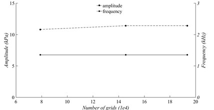
Fig. 4 shows the relationship between grids and calculation results with the velocity of 40 m/s. With the increase of the number of grids, the relative variation error of the peak-peak amplitude and frequency of the pressure curve are both within 5 %, which indicates that the referenced number of grids have little effect on the results. It can be considered that the 145584 grids have reached grid independent.
With the velocity of 40 m/s, the curves of the volume flow rate at different sections of the resonator under stable oscillation are shown in Fig. 5. It can be seen that the curves present periodic changes, which are similar to sinusoidal waveforms. The repeated compression and expansion of the air inside the resonator are presented by periodic rise and fall of the curve. Besides, with closer to the end of the resonator, the volume flow rate becomes smaller and smaller until it is zero at the end.
Fig. 5Volume flow rate at different sections of the resonator
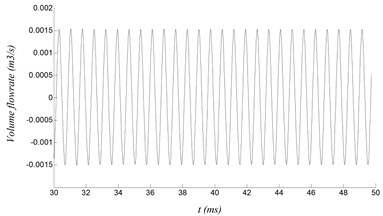
a) Length of 10 mm
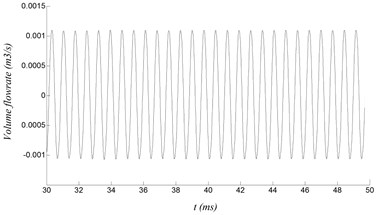
b) Length of 30 mm
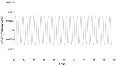
c) Length of 40 mm
4.2. Standing wave characteristic
Fig. 6 shows a cycle of the pressure and the axial velocity at point B with velocity of 60 m/s. is the period time of the curve. Apparently, the curve of pressure and axial velocity are both similar to sinusoidal wave, and the phase difference is about 90 degree. The phase difference of 90 degree indicates the existence of a standing wave sound field inside the resonator. The property of the standing wave are represented by the amplitude of sound pressure and axial velocity distributed along the central axis of the resonator, as shown in Fig. 9 and Fig. 10, respectively. The pressure anti-node and the axial velocity node appear at the closed end of the resonator. Meanwhile, the open end of the resonator is the pressure node, where the pressure is superimposed.
As shown in Fig. 7, the pressure distributed along the axial can be expressed by:
where , where is a wave number, is the amplitude of the pressure at the closed end of the resonator.
Similarly, as shown in Fig. 8, the axial velocity can be expressed by:
where , where is a wave number, is the amplitude of the axial velocity at the open end of the resonator.
Fig. 6A cycle of pressure and axial velocity
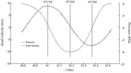
Fig. 7Pressure distributed on the axis of the resonator
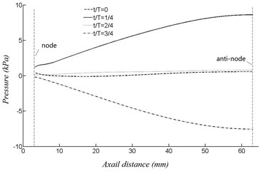
Fig. 8Velocity distributed on the axis of the resonator
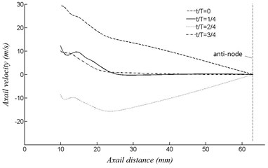
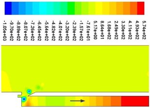
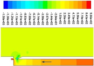
Fig. 9Periodic velocity contours
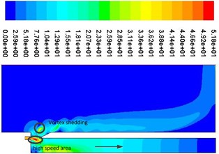
a)0
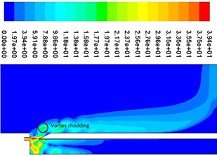
b)0.25
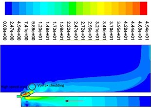
c)0.5
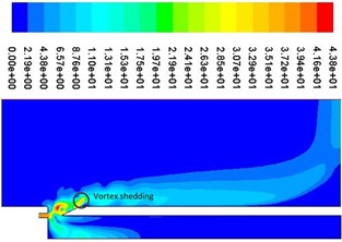
d)0.75
Fig. 9 shows a cycle of velocity contours. It can be seen that vortex shedding is presented near the resonator tip, which can produce edge tone and cause the change of airflow velocity and pressure at the mouth of the cavity, which can determine the compression and expansion of air inside the resonator. As shown in Fig. 9(a), when the jet (high speed area) is in the internal flow field, the pressure at the mouth of the resonator is lower than that of the external field because of the entrapment effect. Air is entered into the resonator from the external field, which can result air compressed and pressure increased. The process of air compression can be shown from Fig. 10(a) to Fig. 10(b). Apparently, as shown in Fig. 9(c), when the jet (high speed area) is in the external flow field, the pressure at the mouth of the resonator is higher than that of the external field because of the entrapment effect. Air is ejected from the internal field, which can result air expanded and pressure decreased inside the resonator. The process of air expansion can be shown from Fig. 10(c) to Fig. 10(d). Repeatedly, a standing wave is formed inside the resonator, which can provide a stable excitation source.
Fig. 10Periodic pressure contours
a)0
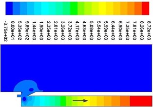
b)0.25
c)0.5
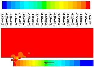
d)0.75
4.3. Frequency characteristic
Fig. 11 represents the excitation frequency variation with velocity. Theoretically, the first-order frequency of the acoustic mode of the resonator is 1417 Hz and the third-order is 4150 Hz [22], respectively. The excitation frequencies are distributed near the acoustic modes of the resonator, which indicates that there are captured. With different velocity segment, the excitation frequency is different, and there will be presented frequency conversion from the first-order to the third-order and from the third-order to the first-order.
Fig. 11Excitation frequency variation with velocity
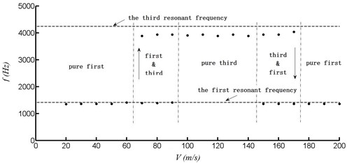
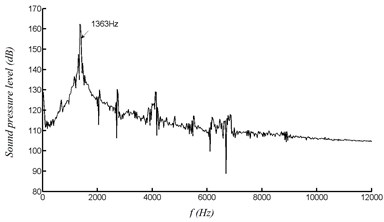
Specifically, within the velocity range of 20 to 60 m/s, the excitation frequency is distributed on the first-order. Within the range of 70 to 90 m/s, it begins transition from the first order to the third order. The pressure curve and frequency spectrum at point A with velocity of 80 m/s can be shown in Fig. 12. Within the range of 100 to 140 m/s, it is fully distributed on the third-order frequency. The pressure curve and frequency spectrum at point A with velocity of 120 m/s can be shown in Fig. 13. Within the range of 150 to 170 m/s, it begins transition from the third order to the first order. Within the range of 180 to 200 m/s, it is distributed on the first-order again.
Fig. 12Pressure at point A with velocity of 80 m/s
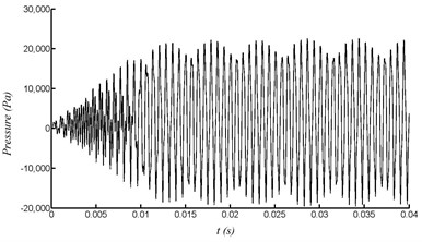
a) Pressure variation with time
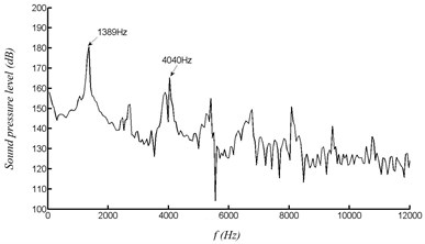
b) FFT
Fig. 13Pressure at point A with velocity of 120 m/s
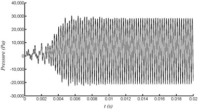
a) Pressure variation with time
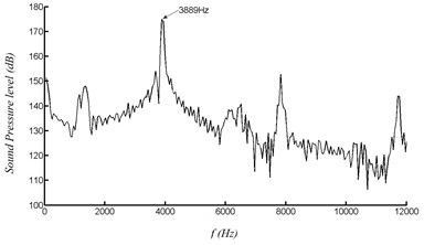
b) FFT
5. Conclusions
In this paper, the characteristics of multi-harmonic excitation of the piezoelectric generator are simulated and analyzed. The results are as follow:
1) The pressure and the volume flowrate inside the resonator finally approximate a stable sinusoidal waveform after a short oscillation. The maximum magnitude of volume flow rate occurs at the open end of the resonator while the pressure reaches the maximum magnitude at the closed end.
2) The phase difference between the curve of pressure and axial velocity is about 90 degree, which indicates the existence of a standing wave sound field formed inside the resonator. The repeated compression and expansion of air inside the resonator can provide a stable excitation source.
3) The excitation frequencies of the generator are captured by the acoustic modes of the resonator. With different velocity segment, the frequencies are presented conversion between the first order and the third order. The multi-harmonic excitation energy exchange scheme can improve the adaptive range of the airflow velocity.
References
-
Wang Shuo, Ding Lu Standardization situation and requirement of internet of things wireless senor networks. China Standardization, Vol. 21, 2018, p. 69-73.
-
Qitao Zhou, Jun Gyu Park, Kyeong Nam Kim Transparent-flexible-multimodal triboelectric nanogenerators for mechanical energy harvesting and self-powered sensor applications. Nano Energy, Vol. 48, 2018, p. 471-480.
-
Priya S., Inman D. J. Energy Harvesting Technologies. Springer, 2009.
-
Lei Jun-Ming An air-driven fluidic resonance piezoelectric generator for fuze. Journal of Detection and Control, Vol. 31, Issue 1, 2009, p. 23-26.
-
Xu Wei, Wang Jiong, Lu Jing MEMS air-driven fluidic resonance piezoelectric generator for fuze. Journal of Detection and Control, Vol. 33, Issue 1, 2011, p. 9-13.
-
Hernandez R., Jung, Matveev K. I. Acoustic energy harvesting from vortex-induced tonal sound in a baffled pipe. Journal of Mechanical Engineering, Vol. 225, 2011, p. 1847-1850.
-
Wang D. A. Piezoelectric energy harvesting from flow induced vibration. Journal of Micromechanics and Microengineering, Vol. 20, 2010, p. 025019.
-
Zou HuaJie, Chen HeJuan, Zhu Xiaoguang Piezoelectric energy harvesting from vibration induced by jet-resonator system. Mechatronics, Vol. 26, Issue 2, 2015, p. 29-35.
-
Zou HuaJie, Chen HeJuan, Liang Yi Study of airflow-induced acoustic characterization of fuze vibration piezoelectric generator. Journal of Acta Armamentarii, Vol. 36, Issue 3, 2015, p. 610-619.
-
Zou HuaJie, Zhang JianGhua, Chen HeJuan Parametric analysis of fuze airflow vibration piezoelectric generator. Journal of Acta Armamentarii, Vol. 38, Issue 10, 2017, p. 2055-2061.
-
Li Z., Li J., Chen H. Experimental research on excitation condition and performance of airflow-induced acoustic piezoelectric generator. Micromachines, Vol. 11, Issue 10, 2020, p. 913.
-
Kan Junwu, Lv Peng, Wang Jin, et al. Performance analysis and test of vortex induced vibration piezoelectric wind harvester. Transactions of the Chinese Society for Agricultural Machinery, 2021.
-
Shu Chang, Zhang Jiantao, Wu Song Piezoelectric wind energy harvester with resonant cavity. Journal of Vibration and Shock, Vol. 37, Issue 3, 2018, p. 22-26.
-
Wen Sheng, Li Shenghua, Zhang Jiantao Design and experiment of vortex-induced vibration self-generating device based on principle of resonant acoustic amplification. Agricultural Machinery, Vol. 48, Issue 11, 2017, p. 204-214.
-
Wang Lei The Characteristic and Experimental Research of Multi-Resonant Frequency Piezoelectric Vibration Energy Harvesting Structure. Beijing Jiaotong University, 2010.
-
Xuhui Zhang, Wenjuan Yang, Meng Zuo, et al. An arc-shaped piezoelectric bistable vibration energy harvester: modeling and experiments. Sensors, Vol. 18, Issue 12, 2018, p. 4472.
-
Wang Guangqing, Zhao Zexiang, Liao Wei Hsin, et al. Characteristics of a tri-stable piezoelectric vibration energy harvester by considering geometric nonlinearity and gravitation effects. Mechanical Systems and Signal Processing, Vol. 138, 2020, p. 106571.
-
Chen Bing, Shi Yutong, Zhang Lijie Analytical model and tests for a hybrid energy harvester based on broadband multi-mode. Journal of Vibration and Shock, Vol. 39, Issue 13, 2020, p. 198-253.
-
Masataka Miyamoto, Yasunori Ito, Kin’ya Takahashi Numerical study on sound vibration of an air-reed instrument with compressible LES. arXiv preprint arXiv:1005.3413, 2010.
-
Sun Daming, Xu Ya, Chen Haijun, et al. A mean flow acoustic engine capable of wind energy harvesting. Energy Conversion and Management, Vol. 63, 2012, p. 101-105.
-
Anderson John D. Computational Fluid Dynamics. Machine Industry Press, Beijing, 2012.
-
Zou HuaJie, Zhang JianGhua, Chen HeJuan Experimental analysis and estimating of the vibration frequency of small fuze airflow-induced vibration piezoelectric generator. Journal of Detection and Control, Vol. 39, Issue 6, 2017, p. 35-39.
Cited by
About this article

The research is financially supported by the Jiangsu Colloge “Qing Lan Project” of China, the Jiangsu Colloge Natural Science Foundation of China, the Changzhou Applied Basic Research Plan of China (CJ20200010), the High-end Research Project of Jiangsu Vocational Professional Teacher of China (2020GRGDYX036).
