Abstract
In order to meet the requirements of airflow vibration piezoelectric generator, and solve the critical issue of stable excitation force, the key is to effectively control structure sensitive parameters. The range of structural parameters of airflow excitation device are optimized by simplified orthogonal test. The result shows that corresponding to different resonator lengths, it approximates a linear increasing trend between the amplitude of excitation force and airflow velocity, and the greater length owns the smaller slope, and vice versa. It is relatively complex for the space and ring gaps, too big or too small gap would make the amplitude smaller or even no waveform formed. The length of resonator is the main factor impacting on the frequency of excitation sound pressure, and the frequency decreases with the increase of the length, presenting an inverse relationship, and the space and ring gaps have less effect on the frequency. Therefore, for high airflow velocity, the stable excitation force of high amplitude and frequency can be obtained by short resonator. In addition, reasonable space and ring gaps are also important for ensuring bigger amplitude of excitation sound pressure. The resulting sensitive parameter values of sound excitation device can be used as references for engineering design.
1. Introduction
As the miniaturized development trend of aircrafts, small physical powers supplied complicated application systems of microelectronics system are desperately needed. For airflow vibration piezoelectric generator [1], the incoming airflow can be utilized to drive the piezoelectric transducer vibration to generate electricity. And the operational principle can be described two processes as the process of acoustic excitation induced by airflow and the process of electricity generation. It is simple in structure and has no moving parts. Therefore, wide applied prospects can be expected on the condition of increasing the output power by improving the driving performance of the generator.
Many scholars have performed related research on this kind of airflow vibration piezoelectric generator theoretically and experimentally. Li Ying-Ping studied the energy conversion mechanism and the natural frequency of vibrating piezoelectric transducer [1]. Ni Hui et al. derived the natural frequency of the piezoelectric transducer and the resonator [2]. Based on Literature [1], Lei Jun-Ming et al. designed a piezoelectric transducer with a diameter of 34 mm, and then simply measured the output voltage and output power of the airflow vibration piezoelectric generator [3]. Xu Wei et al. have studied the vibration displacement response of the piezoelectric and the output voltage of the generator by simulation [4]. He Peng designed an air-inlet with airflow conditioning function and analyzed the flow field inner the inlet [5]. Li Fei et al. have studied the process of vortex shedding in the flow field [6]. According to the principle of frequency pump [7], Zou Hua-Jie et al. designed a small structure of the airflow vibration piezoelectric generator based on the structure of nozzle-resonator, which is composed of an airflow excitation device and a piezoelectric transducer, shown in Fig. 1 [8-10]. They focused on the process of acoustic excitation induced by airflow and studied the operational principle and characterization of airflow-induced acoustic excitation through simulation and experiment [8]. Then they studied the characterization of the output power by measuring output voltage across the road and calculating related electrical [9]. And they also analyzed the fixed method of the piezoelectric transducer [10]. The literatures survey all studied the excitation mechanism or the energy conversion of this kind of airflow vibration piezoelectric generator. There are few research reports on optimization of structural parameters for the excitation force.
Fig. 1Schematic of airflow vibration piezoelectric generator [8-10]
![Schematic of airflow vibration piezoelectric generator [8-10]](https://static-01.extrica.com/articles/19113/19113-img1.jpg)
There are many optimization methods, most of which are optimized based on some kind of improved algorithm. Wu Deng, Huimin Zhao, Li Zou, et al. proposed a genetic and ant colony adaptive collaborative optimization (MGACACO) algorithm to overcome the deficiencies of weak local search ability in genetic algorithms and slow global convergence speed in ant colony optimization algorithm for solving complex optimization problems [11]. The chaotic optimization method, multi-population collaborative strategy and adaptive control parameters are introduced into the proposed MGACACO algorithm. Wu Deng, Rui Yao, Huimin Zhao, et al. proposed a novel intelligent diagnosis method for the faults of the motor bearing by improving particle swarm optimization algorithm and least squares support vector machines [12]. Wu Deng, Huimin Zhao, Xinhua Yang, et al. proposed an improved adaptive particle swarm optimization (DOADAPO) algorithm based on making full use of the advantages of Alpha-stable distribution and dynamic fractional calculus for an efficient multi-objective optimization model of gate assignment problem [13].Wu Deng, Huimin Zhao, Jingjing Liu et al. proposed an improved CACO algorithm based on adaptive multi-variant strategies (CACOAMS) for solving complex optimization problems in order to avoid the local optimization solution and stagnation, guarantee learning rate of the different dimensions for each ant [14]. H. M. Zhao, D. Y. Li, W. Deng et al. proposed a novel vibration suppression method based on fractional order Proportional-Integral-Derivative (PID) controller to suppress the vibration of motor [15]. Huimin Zhao, Meng Sun, Wu Deng et al. proposed a new fault feature extraction method, called the EDOMFE method based on integrating ensemble empirical mode decomposition (EEMD), mode selection, and multi-scale fuzzy entropy for mechanical fault diagnosis [16]. Bin Gu, Victor S. Sheng presented a new equivalent dual formulation for -SVC and proposed a robust -SvcPath, based on lower upper decomposition with partial pivoting [17]. Theoretical analysis and experimental results verify that the proposed robust regularization path algorithm can avoid the exceptions completely, handle the singularities in the key matrix, and fit the entire solution path in a finite number of steps. In addition, the orthogonal test method is also the most intuitive and simple optimization method.
In order to ensure stable excitation force, the key is to effectively control structure sensitive parameters. Therefore, this paper focuses on the process of acoustic excitation induced by airflow. The range of structural parameters of airflow excitation device are optimized by simplified orthogonal test method to ensure good waveform with high amplitude and frequency.
2. Experiment method
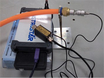
As the same experiment method in Literature [9], the schematic of the experimental system is shown in Fig. 2 and Fig. 3 presents a photo of the experiment. The related measurement devices can be described as follows:
A CYY28 pressure sensor is utilized to measure sound pressure at the closed end of the resonator, as illustrated by P in Fig. 2. The signals from the pressure sensor is collected by a data collector and then stored on computer.
A calibrated flow meter is employed for measuring mean flow rate. The mean flow rate is changed by adjusting the flow control valve.
Fig. 2Schematic of the experimental system
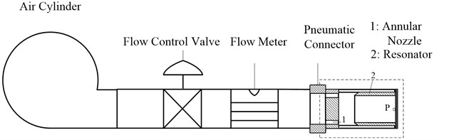
Fig. 3Photo of the experiment
3. Experimental results
When optimizing structural parameters of the airflow excitation device, as shown in Fig. 1, four structural parameters are mainly considered: 1) : the length of the resonator; 2) : the diameter of the resonator; 3) : the space between the nozzle and the resonator; 4) : the gap of the annular nozzle. For simplicity, the diameter of the resonator is determined as a fixed value ( 10 mm) and the other three parameters as variable values.
In order to get the curve of the excitation force and fully understand the influence of structure parameters on excitation force, the experiments are tested and analyzed under the condition of a single parameter at different values to simplify the orthogonal test.
3.1. Influence of the length on excitation force
For the conditions of the plane wave propagation, when is 10 mm, should be greater than 5 mm. And then, when the influence of the length on excitation force is analyzed, the structure parameters of the designed prototype are as follows: 3 mm, 1 mm, 7, 10, 15 and 20 mm.
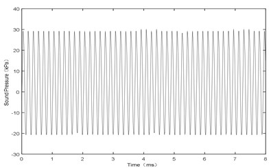
Fig. 4L= 10 mm and V= 106 m/s, sound pressure at point P
a) Amplitude
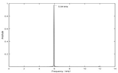
b) Frequency
Fig. 4 shows the sound pressure at point P with an input airflow velocity of 106 m/s. The curve of the sound pressure follows a sine wave, shown in Fig. 4(a), and the main frequency is about 5.94 kHz, shown in Fig. 4(b). Therefore, it can be seen that, the amplitude and the frequency both reach at a stable state. The experimental results are as follows:
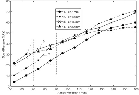
(1) Fig. 5 shows the amplitude of sound pressure various with airflow velocity. It approximates a linear increasing trend with increasing airflow velocity for all the lengths. When airflow velocity is less than 70 m/s, the smaller length would make the amplitude smaller with increasing airflow velocity. In addition, when the airflow velocity is more than 90 m/s, apparently the smaller length would make the amplitude bigger with increasing airflow velocity. In a word, the bigger length owns the smaller slope, and vice versa.
Fig. 5Sound pressure-airflow velocity
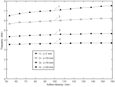
(2) Fig. 6 shows the frequency of sound pressure various with airflow velocity. At the same velocity, the frequency decreases with the increase of the length, presenting an inverse relationship. When the length is 20 mm, the frequency offset is 157 Hz and the relative error is less than 4.3 %. The bigger length would make the frequency offset smaller.
According to the above analysis, under the condition of high airflow velocity, the short resonator can be chosen to get stable excitation force with high frequency and amplitude.
Fig. 6Frequency-airflow velocity
3.2. Influence of the space on excitation force
When the influence of the space on excitation force is analyzed, the structure parameters of the designed prototype are as follows: 7 mm, 1 mm, 2, 2.5, 3, 3.5 and 4 mm.
Fig. 7X= 3 mm and V= 74 m/s, sound pressure at point P
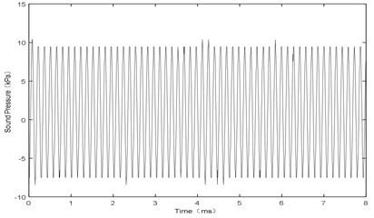
a) Amplitude
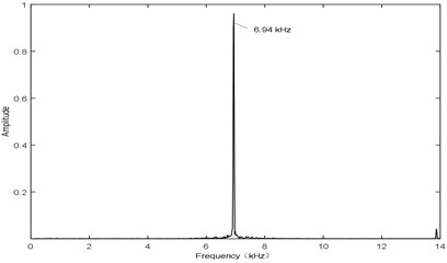
b) Frequency
Fig. 7 shows the sound pressure at point P with airflow velocity of 106 m/s. It has the same waveform as Fig. 4 with the frequency of 6.94 kHz. Therefore, it can be seen that, the amplitude and the frequency both reach at a stable state. The experimental results are as follows:
(1) Fig. 8 shows the amplitude of sound pressure various with airflow velocity. During low airflow velocity (50-70 m/s), the smaller space would make the amplitude larger, and the bigger space would make the amplitude smaller or even no sound vibration, as shown in Fig. 9. The reason is that during flow from the nozzle to the resonator, the loss of airflow energy is serious because of the bigger space. When arriving the resonator, it is small enough to generate sound, resulting in smaller amplitude of sound pressure or no sound vibration at the end of the resonator. In addition, during high airflow velocity (90-160 m/s), the smaller space would make the amplitude smaller or even no sound vibration, as shown in Fig. 10 and Fig. 11. The reason is that the oscillation is not formed by jet when the space is smaller, resulting in smaller amplitude of sound pressure or no sound vibration at the end of the resonator.
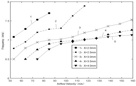
(2) Fig. 12 shows the frequency of sound pressure various with airflow velocity. It approximates a linear increasing trend with increasing airflow velocity for all the spaces. Frequency increasing capacity of the small space is strong and the increase is great. Anyway, the smaller space would make the frequency bigger, but the bigger space would make the frequency more stable.
According to the above analysis, under the condition of high airflow velocity, in order to ensure sound vibration and get high frequency with good stability, the space cannot be less than 3.0 mm.
Fig. 8Sound pressure-airflow velocity
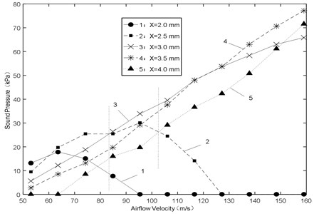
Fig. 9X= 4.0 mm and V= 53 m/s, sound pressure at point P
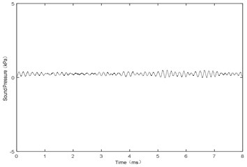
Fig. 10X= 2.0 mm and V= 106 m/s, sound pressure at point P
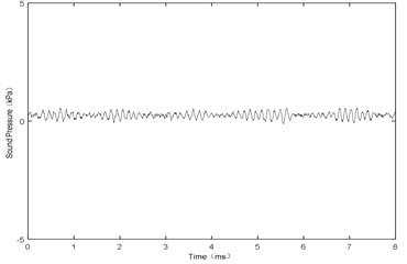
Fig. 11X= 2.5 mm and V= 127 m/s, sound pressure at point P
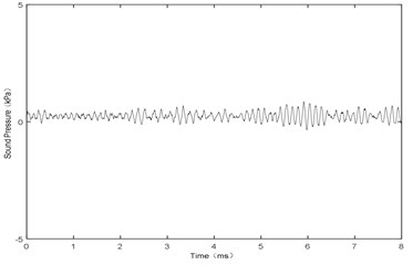
Fig. 12Relationship between frequency and airflow velocity
3.3. Influence of the gap on excitation force
When the influence of the gap on excitation force is analyzed, the structure parameters of the designed prototype are as follows: 8 mm, 3 mm, 0.5, 1 and 1.5 mm.
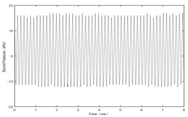
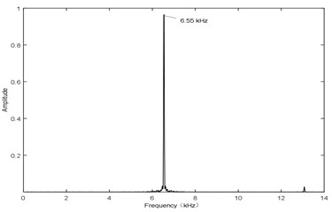
Fig. 13 shows the sound pressure at point P with airflow velocity of 106 m/s. It has the same waveform as Fig. 4 and Fig. 7 with the frequency of 6.55 kHz. Therefore, it can be seen that, the amplitude and the frequency both reach at a stable state. The experimental results are as follows:
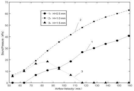
(1) Fig. 14 shows the amplitude of sound pressure various with airflow velocity. During low airflow velocity (50-70 m/s), the smaller gap would make the amplitude smaller or even no sound vibration, as shown in Fig. 15. The reason is that the amplitude of jet oscillation is small when the gap is small ( 0.5 mm), resulting in smaller amplitude of sound pressure or no sound vibration at the end of the resonator. In addition, during high airflow velocity (100-160 m/s), the big gap would make the amplitude smaller or even no sound vibration, as shown in Fig. 16. The reason is that the oscillation is not formed by jet when the gap is big ( 1.5 mm), resulting in smaller amplitude of sound pressure or no sound vibration at the end of the resonator. The results show that the amplitude is always at the maximum under the condition of 1.0 mm, and there is a critical value of the gap to make the amplitude a linear increasing trend with increasing airflow velocity.
Fig. 13H= 1 mm and V= 85 m/s, sound pressure at point P
a) Amplitude
b) Frequency
Fig. 14Sound pressure-airflow velocity
(2) Fig. 17 shows the frequency of sound pressure various with airflow velocity. It approximates a linear increasing trend with increasing airflow velocity for all the gaps, and the big gap would make high frequency. At high velocity, the frequency offset is less than 500 Hz and the relative error is less than 8 %.
According to the above analyses, in order to get stable excitation force with high frequency and amplitude, the gap should be controlled within a reasonable range.
Fig. 15H= 0.5 mm and V= 53 m/s, sound pressure at point P
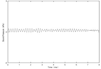
Fig. 16H= 1.5 mm and V= 116 m/s, sound pressure at point P
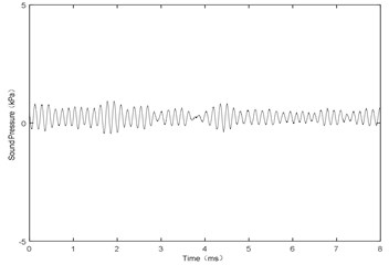
Fig. 17Frequency-airflow velocity

The founding sponsors had no role in the design of the study; in the collection, analyses, or interpretation of data; in the writing of the manuscript, and in the decision to publish the results.
4. Conclusions
The results are as follows:
1) During low airflow velocity, with the increase in the airflow velocity, the smaller length of the resonator is, the smaller the amplitude of excitation force will be; small space would lead to a large amplitude, and the big space or the small gap would make the amplitude small or even no sound vibration generated.
2) In addition, during high airflow velocity, as the airflow velocity increases, apparently the smaller length of the resonator is, the larger the amplitude of excitation force will be; the small space or the big gap would make the amplitude small or even no sound vibration.
3) Moreover, the length of the resonator is the main factor impacting on the frequency of excitation force, and the frequency decreases with the increase of the length, presenting an inverse relationship; the space and the gap have less effect on the frequency. The resulting sensitive parameter values of sound excitation device can be used as references for engineering design.
References
-
Li Yingping The Principle of Fuze Piezoelectric Power Supply and Experimental Investigations. Nanjing University of Science and Technology, Nanjing, 2003.
-
Li Hui, Gao Min, Wang Guang Long Principle and analysis of piezoelectric fluidic generator for fuze. Power Technology, Vol. 33, Issue 12, 2009, p. 1120-1122.
-
Lei Jun Ming An air-driven fluidic resonance piezoelectric generator for fuze. Journal of Detection and Control, Vol. 31, Issue 1, 2009, p. 23-26.
-
Xu Wei, Wang Jiong, Lu Jing MEMS air-driven fluidic resonance piezoelectric generator for fuze. Journal of Detection and Control, Vol. 33, Issue 1, 2011, p. 9-13.
-
He Peng Numerical Simulation of Airflow Control Inlet Internal Flow Field of Fuze On-Boarded Generator. Nanjing University of Science and Technology, Nanjing, 2012.
-
Li Fei Numerical analysis of vortex shedding behavior of piezoelectric microgenerator from dynamic airflow induced vibration. Advanced Materials Research, Vol. 694, 2013, p. 1595-1601.
-
Priya S., Inman D. J. Energy Harvesting Technologies. Springer, New York, 2009, p. 26-27.
-
Zou Huajie, Chen Hejuan, Liang Yi Study of airflow-induced acoustic characterization of fuze vibration piezoelectric generator. Journal of Acta Armamentarii, Vol. 36, Issue 3, 2015, p. 610-619.
-
Zou Huajie, Chen Hejuan, Zhu Xiaoguang Piezoelectric energy harvesting from vibration induced by jet-resonator system. Mechatronics, Vol. 26, Issue 2, 2015, p. 29-35.
-
Zou Huajie, Chen Hejuan Fixation methods of sound tube of micro ringtone airflow piezoelectric generator. Journal of Detection and Control, Vol. 36, Issue 3, 2014, p. 25-30.
-
Wu Deng, Zhao Huimin, Zou Li, Li Guangyu, Yang Xinhua, Wu Daqing A novel collaborative optimization algorithm in solving complex optimization problems. Soft Computing, Vol. 21, Issue 15, 2017, p. 4387-4398.
-
Deng Wu, Yao Rui, Zhao Huimin, Yang Xinhua, Li Guangyu A novel intelligent diagnosis method using optimal LS-SVM with improved PSO algorithm. Soft Computing, 2017, https://doi.org/10.1007/s00500-017-2940-9.
-
Deng Wu, Zhao Huimin, Yang Xinhua, Xiong Juxia, Sun Meng, Li Bo Study on an improved adaptive PSO algorithm for solving multi-objective gate assignment. Applied Soft Computing, Vol. 59, 2017, p. 288-302.
-
Deng Wu, Zhao Huimin, Liu Jingjing, Yan Xiaolin, Li Yuanyuan, Yin Lifeng, Ding Chuanhua An improved CACO algorithm based on adaptive method and multi-variant strategies. Soft Computing, Vol. 19, Issue 3, 2015, p. 701-713.
-
Zhao H. M., Li D. Y., Deng W., Yang X. H. Research on vibration suppression method of alternating current motor based on fractional order control strategy. Proceedings of the Institution of Mechanical Engineers Part E-Journal of Process Mechanical Engineering, Vol. 231, Issue 3, 2017, p. 786-799.
-
Zhao Huimin, Sun Meng, Deng Wu, Yang Xinhua A new feature extraction method based on EEMD and multi-scale fuzzy entropy for motor bearing. Entropy, Vol. 19, Issue 14, 2017, p. 1-21.
-
Bin Gu, Sheng Victor S. A robust regularization path algorithm for v-support vector classification. IEEE Transactions on Neural Networks and Learning Systems, Vol. 28, Issue 5, 2017, p. 1241-1248.
Cited by
About this article

The research is financially supported by the Natural Science Youth Fund Project of Jiangsu Province under contract No. BK20160296.
