Abstract
This study conducted modal and vibration-characteristic tests using transient excitation and spectrum analysis methods to find the variation law of vibration characteristics of wind wheels with bifurcated tip structures as compared to wind wheels with unmodified tips when the coupling between a wind wheel and its tower is considered. Additionally, a finite element analysis was used to calculate the mechanical characteristics of wind power manoeuvres. The following are the major results of this study. As compared to the non-trailer state, the coupling action of the wind wheel and the tower reduced the static frequency of the unmodified wind wheel and the bifurcated blade tip structure wind wheel under the trailer state. The static frequency of the bifurcated blade tip structure wind wheel under the coupling action decreases more significantly. Compared with the single wind wheel which is not affected by coupling, the dynamic frequency of the whole machine decreases after being affected by coupling, and the bifurcated blade structure has less influence on the coupling effect. Compared with the non-trailer state, the dynamic frequency curves of the two blade tip structure wind wheels in the trailer state decrease, the speed range in the resonance area is shortened, and the corresponding speed in the resonance area is reduced. The results of this study provide data support and design reference for reliable design of wind turbines.
1. Introduction
Traditional energy sources, such as fossil fuels, are often difficult to obtain and cause serious pollution. Wind turbines use wind energy to rotate their blades that are attached to generators, which in turn generate electricity [1]. As the blades and tower of a wind turbine are flexible components, the wind wheel is subject to aerodynamic loads while the wind turbine is under operation, which causes the tower to oscillate, and the oscillation of the tower in turn affects the wind wheel blades. Therefore, analysis of the vibration of the wind turbine wheel and tower when designing wind turbine blades is necessary, to provide a theoretical basis for improving or alleviating wind turbine resonance [2].
At present, domestic and foreign researchers have usually used two modes of analysis to analyze the vibration of wind turbines, namely, numerical calculations and tests. Chen et al. [3] tested the vibration characteristics of wind turbine blades with trailing winglets. This study analyzed the static and dynamic frequency of the blades with trailing winglets installed on vertical wind turbine blades, but they only considered the increase in wind speed without considering its effect on the dynamic frequency. Zhao [4] and others use the operating state of a 1.5 MW wind turbine and the vibration response of the tower to monitor and make data analysis of offshore wind turbine vibration under different operating conditions, using data-driven stochastic subspace identification method, based on the results of the intrinsic frequency to draw Campbell diagrams of the wind turbine in the direction of the FA direction and the direction of the SS, but the lack of targeted analysis. Guo [5] and others validate the effectiveness and accuracy of the computational model by simulating the steady-state response of the NREL 5 MW straight blade; effectively simulating the nonlinear deformation of the swept-back blade and the non-constant aerodynamic characteristics, but did not explore the applicability of the program to other models in depth. Wu et al. [6] conducted an experimental investigation on the static and dynamic frequency of a wind turbine tower, but they did not consider the influence of the centrifugal load on the tower. In terms of numerical calculation, Bai at al. [7] studied and analyzed wind turbine vibration and stress harmonics under rotating excitation airflow by using ANSYS harmonic response analysis, but the effect of centrifugal load was not taken into account. Nazokkar et al. [8] used variable head loss coefficients and variable frequencies, as well as DBG, VBG and Bang-Bang algorithms. To investigate the effect of a semi-active liquid column gas damper (SALCGD) on the control of FOWT vibration under different wind and wave loads. The dynamic response analysis model of the combined wind turbine-damper system is established, and the time course analysis but lack of vibration characteristics is verified. Wang [9] used Matlab to establish a wind load model, imported the wind load into Ansys for transient dynamics simulation analysis of the blade, and designed three kinds of vibration suppression structures according to the different locations of the damping layer: the outer surface of the blade with additional damping structure, the built-in constrained damping structure, and the inner surface of the blade with additional damping structure, to investigate the simulation design of wind turbine blades and vibration suppression and control analysis of the wind condition in the Beibu Gulf Sea area. However, the applicability of this method at vibration frequency is not studied in depth. Ning [10] and others proposed a rigid body finite element method to establish a dynamic model to study the dynamic response of displacement and velocity under a turbulent wind field, and a wind turbine as an example to verify the accuracy of the method, but did not make the analysis of resonance and so on. Hicham [11] used ABAQUS finite element analysis software to analyze a floating wind turbine blade. The study determined the natural modal modes and frequencies of the three-beam blade in the free vibration process to avoid resonance, but no resonance analysis was carried out on the blade while working. Yang [12] employed finite element analysis to analyze the influence of wind shear on the structural dynamics of the blade. The study calculated the structural dynamic characteristics of a blade such as natural frequency, displacement, and stress under wind shear effect, but neglected the variation rule of wind turbine and the fact that the whole machine was affected by the wind shear effect. At present, most of the modification ideas mainly focus on the dynamics of wind turbine blade structure after changing its structure, such as changing the material layer inside the blade.
Wind wheels subjected to aerodynamic loads will exert force on the tower while the tower deformation will affect the wind wheels in reverse. Therefore, changes in the structure of the tip of a blade of the wind wheel cause changes in the aerodynamic loads of the wind wheel, and the coupling relationship between the wind wheel and the tower will affect the vibration performance of the whole machine. Therefore, this study entailed the development of a blade with a bifurcated blade tip by orthogonal test. The vibration characteristics of wind turbines with bifurcated blade tip structures with different parameters are investigated by numerical calculation and wind tunnel tests. The simulation calculation results are corroborated with the analysis of the test data results, and the results of the study provide data support and design references for the dynamics study of the wind turbine and tower.
2. Schematic design
2.1. Blade design principles
2.1.1. Leaf tip velocity ratio
The ratio of the pre-designed wind speed and the linear velocity of the blade tip when the wind turbine blade is in operation is the tip speed ratio , which is calculated as follows:
where – rotational speed (r/s); – angular speed (rad/s); – wind wheel radius (m); – preset wind speed (m/s).
2.1.2. Wilson design method
The Wilson design method was used to design the blades:
where – number of blades; – leaf vein chord length (m); – lift coefficient; – incoming flow angle (°); – axial factor; – circumferential factor; – loss factor of leaf tip; – distance from cross-section to leaf root (m).
From the above Eq. (2) and Eq. (3) can be obtained:
where – leaf tip loss coefficient, .
After considering leaf tip losses, the local wind energy utilization factor is:
After calculating the maximum value of , , , it can be calculated by using Eq. (2):
The incoming flow angle for each foliation can be calculated by Eq. (6), and the torsion angle and chord length can be obtained.
2.2. Modal test
2.2.1. Test object
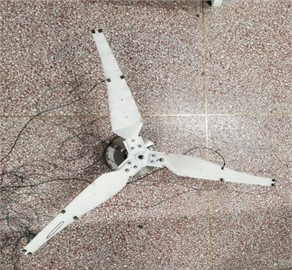
The test was carried out on a small 100 W wind turbine having three blades. The rated wind speed was 8 m/s, and the rated speed was 600 r/min. Tower elevation was 1.6 m. Specific parameters of the blades are shown in Table 1.
Table 1Parameters of the blades
Parameter | Numerical value | Parameter | Numerical value |
Number of blades B | 3 | Chord length of leaf tip / m | 0.041 |
Leaf length / m | 0.65 | Maximum aspect ratios | 4.14 |
Wind wheel diameter / m | 1.3 | Relative thickness | 10.26 % |
Rated tip-speed ratio | 5 | Vane wing | S825 |
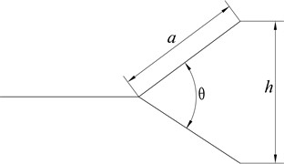
The three-dimensional view of the unmodified tip of the blade and the blade having a bifurcated blade tip structure is shown in Fig. 1, and Fig. 2 presents the diagram of the bifurcated blade tip structure. In the figure, is the angle between the opening and forking of the tip, and the angle between the opening and forking of the bifurcated blade tip structure is 30° and 60°, respectively. The tip length is denoted by a; the tip length of the bifurcated blade tip structure was 47 mm; is the width of the leaf tip, and the width of the bifurcated blade leaf tip structure was 45 mm and 63.5 mm respectively.
Fig. 1Blade structure

a) Unmodified blades

b) Bifurcated blade tip structure
Fig. 2Bifurcated blade tip structure
2.2.2. Test methods and equipment
Using the transient excitation method, the blades were driven by a force hammer in the state of the trailer and non-trailer. Wind wheels in the state of the trailer were installed on the tower using the coupling effect of the wind wheel and the tower. Wind wheels in the state of non-trailer were fixed using a three-jaw chuck without using the coupling effect. After knocking, sensors arranged on the blades collected vibration information generated by the excitation of the blades. The data was first transmitted to the front for data acquisition and then to the switch with a wireless module. Finally, the data transmission system, consisting of the front end for data acquisition and the switch, transmits the collected original information to the computer after conversion. Vibration analysis software, BK Connect, was used to process and analyze the data to get the modal parameters of the wind wheel.
Fig. 3Modal test equipment
a) Sensor display
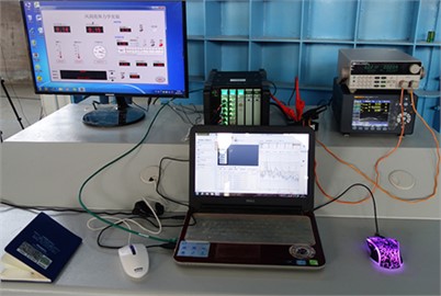
b) Data acquisition system
The force hammer used was a B&K8206 force hammer, the sensor was a 7507 B acceleration sensor, the data acquisition front-end model was a 3053 B 12-channel data acquisition front-end in the data transmission system, and the switch was a 3660 C module wireless LAN cabinet. Photos of the test equipment are given in Fig. 3.
2.2.3. Arrangement of measuring points
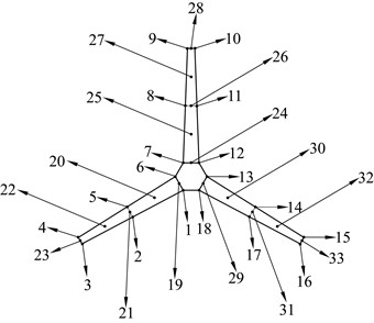
To obtain more accurate results, measuring and excitation sensors were placed at multiple points. The positions of the measuring and excitation points are shown in Fig. 4. Points 1-18 are the measuring points and 19-33 are the excitation points of the force hammer.
Fig. 4Measuring points of the wind wheel
2.3. Vibration characteristics test
2.3.1. Test methods and equipment
The wind turbine vibration test adopts the spectrum analysis method. The wind turbine was installed in front of the wind tunnel, and the rotation plane of the wind turbine was 0.5 m away from the opening of the wind tunnel. After the wind tunnel was opened and the wind turbine rotated, the electronic load meter was used to control the speed of rotation of the wind wheel. The vibration signals of the wind turbine were collected by the three-way acceleration sensors installed on the head and the tower. The collected vibration signals were stored by the data acquisition system and transmitted to the computer for analysis by the data analysis system after conversion to obtain the dynamic frequency of the wind turbine. The test equipment is shown in Fig. 5.
Fig. 5Acceleration sensor
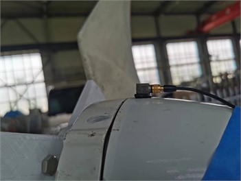
The three-way acceleration sensor used was the 4524B three-way acceleration sensor (Brüel & Kjær), and the electronic load meter used was the IT8512A+ load meter (IDEX).
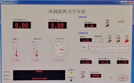
Fig. 6Wind tunnel-vibration characterization test bed page
2.3.2. Measuring points layout
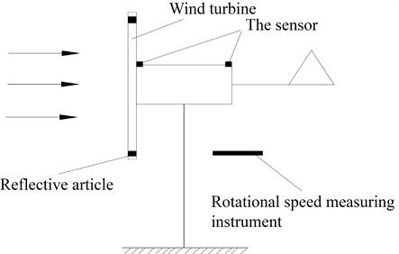
The schematic of the measuring points is shown in Fig. 7. Three-way acceleration sensors were arranged at the front end of the generator and the top of the tower to obtain the vibration signals of the wind turbine as well as the whole machine. The laser speed measuring probe was placed behind the blade rotation plane to obtain the speed information of the wind turbine.
Fig. 7Schematic diagram of measuring points
3. Results
3.1. Modal parameters
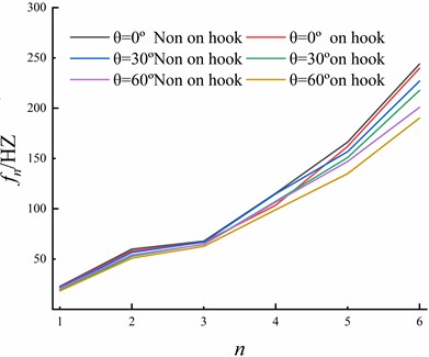
Using multi-point excitation and multi-point response, the modal parameters of the wind turbine and tower are comprehensively analysed under each working condition. The static frequency curves of the wind wheel in the on-hook state and the not-on-hook state are given in Fig. 8. It can be seen from the graph that after coupling with the tower, the static frequency of the wind turbine wheel decreased, and the amplitude of reduction was different after the change in the blade tip structure and introduction of the coupling effect. It can be observed that the amplitude of reduction of the third-order static frequency is small, and the law of the fourth-order static frequency is not evident. According to the data analysis, compared with the wind turbine in the not-on-hook state, the static frequency of the unmodified wind wheel (0°) in the on-hook state decreased by 4.12 % and 3.0 % in the first and second order, respectively, and decreased by 2.61 % and 1.73 % in the fifth and sixth order, respectively. The static frequency of the wind wheel with the bifurcated blade tip structure ( 30°) decreased by 10.29 % and 6.5 % in the first and second order, respectively, and by 3.75 % and 4.06 % in the fifth and sixth order, respectively. The static frequency of the wind wheel with the bifurcated blade tip structure ( 60°) decreased by 11.69 % and 6.01 % in the first and second order, respectively, and by 8.29 % and 5.33 % in the fifth and sixth order, respectively. The wind turbine tower coupling reduces the static frequency of the wind turbine wheel, and the bifurcated blade tip structure increases the influence of the coupling on the static frequency of the wind turbine, wherein the wind wheel with the bifurcated blade tip structure with 60° has the greatest impact.
Fig. 8Static frequencies of each order of wind turbine
3.2. Dynamic frequency
3.2.1. Constant aerodynamic load and increased centrifugal force load
The electronic load meter was connected to the wind turbine system. The aerodynamic load was kept unchanged, i.e., the incoming wind speed was the same. The centrifugal force load was increased, i.e., the electronic load meter was used to control the speed of rotation of the wind wheel. The wind speed maintained the rated wind speed of 8 m/s, and the rotation speed was 500, 600, 700, and 800 rpm respectively. After pre-testing, it was found that the three-way acceleration sensor at the front of the nacelle measured data more accurately than the rear end, so the data collected by the sensor at the front of the nacelle was used in the analysis.
Fig. 9The centrifugal force increases the dynamic frequency of the wind wheel
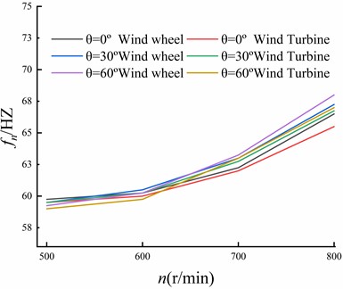
Fig. 9 shows the first-order vibration frequency of the wind turbine when the centrifugal load of the wind turbine is increased, as measured by the three-way accelerometer installed at the front of the nacelle. It can be observed from the graph that the dynamic frequency of the whole machine decreased. The dynamic frequency decreased slightly when the rotation speed was 500 r/min, and there was a more prominent decrease in the dynamic frequency when the rotation speed was 800 r/min. Compared with the dynamic frequency of the wind wheel, the dynamic frequency of the unmodified wind turbine ( 0°) was reduced by 1.5 % at 800 r/min. The dynamic frequency of the complete machine with bifurcated blade tip structure ( 30°) was reduced by 0.74 % at 800 r/min, while that of 60° was reduced by 1.47 % at 800 r/min. This indicates that when the pneumatic load remains unchanged and the centrifugal force load increases, the dynamic frequency of the whole machine decreases and the magnitude decreases with the increase of centrifugal force loads. However, the effect of the bifurcated blade tip structure on the reduction of the dynamic frequency of the whole machine is not evident.
3.2.2. Constant centrifugal force load and increased aerodynamic load
When the centrifugal force load was kept unchanged and the pneumatic load was increased, the speed of the wind wheel was controlled by an electronic load meter. The speed of the wind wheel was kept constant, and the pneumatic load was gradually increased by adjusting the wind speed at the outlet of a wind tunnel. The test maintained the speed of the wind wheel at 600 r/min, and the wind speed was set at 5, 6, 7, and 8 m/s.
As shown in Table 2, when the centrifugal force load was unchanged and the pneumatic load was increased, the dynamic frequency of the wind wheel and the whole machine changed slightly, where the increase of the pneumatic load and the change amplitude was less than 1 Hz. Compared with the wind wheel, the dynamic frequency of the whole machine tends to decrease, but it is not very apparent. This indicates that the increase of aerodynamic load is not the main influencing factor for the variation of dynamic frequency of the wind wheel and the whole machine.
Table 2Pneumatic load increases the dynamic frequency of the wind wheel and the whole machine (Hz)
Wind speed (m/s) | Wind wheel | Wind Turbine | ||||
0° | 30° | 60° | 0° | 30° | 60° | |
5 | 59.50 | 60.25 | 60.25 | 59.25 | 59.75 | 60.00 |
6 | 59.75 | 60.25 | 60.50 | 59.50 | 60.00 | 60.25 |
7 | 60.00 | 60.75 | 60.75 | 60.00 | 60.50 | 60.50 |
8 | 60.25 | 60.50 | 60.25 | 60.00 | 60.50 | 60.00 |
4. Numerical simulation
To obtain the dynamic characteristics of wind turbines under trailer and non-trailer conditions, the wind turbine used in the test was used as the model for numerical simulation. The three-dimensional model was imported into the meshing software for meshing, and the fluid grid and solid finite element model were obtained. The fluid grid is shown in Fig. 10.
Fig. 10Mesh generation
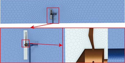
In numerical computation, the quality of mesh delineation directly affects the computational results, so it is required that the mesh not only achieve a certain degree of accuracy but also have a fast convergence speed of computation. In this paper, 6 groups of meshes with good convergence effects are selected for grid-independent verification. As shown in Table 3, from the 1st group to the 4th group with the grid number of 350,000-400,000, the grid has a large impact on the wind turbine output power, and the change between groups is more than 4.68 %; from the 4th group, the change between groups is less than 0.89 %. This indicates that the effect of the grid on the power is negligible in this grid interval. To save calculation time and calculation accuracy, the number of grids is selected as 400,000 in this paper.
Table 3Verification of grid-independence
Group | 1 | 2 | 3 | 4 | 5 | 6 |
Grid number | 350000 | 300000 | 350000 | 400000 | 450000 | 500000 |
Power output /W | 86.3 | 91.6 | 95.8 | 100.5 | 101.4 | 102.1 |
The solid finite element model included a single wind wheel model (non-trailer state wind wheel): A three-blade wind wheel was formed by a circular array of unmodified blades spaced 120° from the bifurcated blade tip blades.
The complete machine model (trailer-state wind wheel) was as follows. The whole machine model including the wind wheel, tower, shaft, and engine room was connected between different components by the MPC multi-point constraint coupling algorithm. Fluid-solid coupling method was used to study and analyze the dynamic characteristics of the wind wheel with the continuous increase in rotational speed.
Campbell diagram was used to analyze the dynamic characteristics of the wind turbines in trailer state and non-trailer state. Fig. 10 shows the Campbell diagram of the first-order dynamic frequency of the wind turbine. For three-blade wind turbines, triple frequency (3P) was selected as the main frequency, and the main frequency (+10 %) was set as the resonance zone. The difference between the wind turbine dynamic frequency curve and the transverse coordinates of the two intersecting points in the resonance zone was the frequency width. The shorter the frequency curve was, the farther the speed distance from the resonance zone to the rated speed, and the smaller the probability of wind turbine resonance.
Fig. 11First-order Campbell diagram of a wind turbine
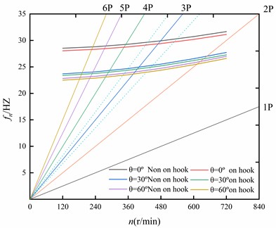
From the analysis of Fig. 11, the frequency width of the unmodified wind wheel ( 0°) under a non-trailer state was 1.79 Hz, and the speed in the resonance zone was 478.03 r/min; the frequency width of the wind wheel with the bifurcated blade tip structure ( 30°) was 1.54 Hz, and the speed in resonance zone was 399.69 r/min; the frequency width of the wind wheel with the bifurcated blade tip structure ( 60°) was 1.44 Hz, and the speed in resonance zone was 384.37 r/min. For the wind wheels under trailer state, the frequency width of unmodified wind wheel ( 0°) was 1.76 Hz, and the speed in resonance zone was 469.41 r/min; the frequency width of the wind wheel with the bifurcated blade tip structure ( 30°) was 1.47 Hz, and the speed in resonance zone was 393.37 r/min; the frequency width of the wind wheel with the bifurcated blade tip structure ( 60°) was 1.39 Hz, and the speed in resonance zone was 378.63 r/min. the results of the analysis reveal that the dynamic frequency curve of the wind wheel under the trailer state is lower than that under the non-trailer state, which indicates that the duration of the wind wheel in the resonance area is shorter and the speed in the resonance area is far from the rated speed. The first-order dynamic frequency of the wind turbine decreased remarkably when the blade was modified, and the dynamic frequency decreased continuously and slightly with the increase of the opening angle of the bifurcated blade tip structure.
5. Conclusions
By analyzing the data from simulation calculations and wind tunnel tests, the results show that the two results coincide and the accuracy of the following conclusions can be determined:
1) By analyzing the static frequencies of wind wheels in different states, it can be seen that the first, second, fifth, and sixth static frequencies of the wind turbines in the trailer state decrease, and the bifurcated blade tip structure can increase the reduction extent of static frequencies. The wind turbines having the bifurcated blade tip structure with 60° show the most significant increase.
2) The dynamic frequency of the whole machine decreases, the whole machine frequency decreases more with the increase of centrifugal force load. The bifurcated blade tip structure has little influence on the dynamic frequency of the whole machine when the centrifugal force load increases and the law is not evident. When the aerodynamic load increases and the centrifugal force load remains unchanged, the amplitude of dynamic frequency change between the wind turbine and the whole machine is small.
3) The dynamic frequency curve of the wind wheel passes through the resonance band more quickly in the hang-up condition, and the speed corresponding to the resonance zone decreases, even less than the rated speed. The dynamic frequency of the wind wheel can be considerably reduced by the bifurcated blade tip structure, and the dynamic frequency can be further reduced by increasing the opening angle of the bifurcated blade tip structure.
References
-
Z. G. Ji, “Research on current situation and development trend of wind power industry in China,” (in Chinese), China Equipment Engineering, Vol. 4, pp. 217–218, 2020, https://doi.org/10.3969/j.issn.1671-0711.2020.18.126
-
L. J. Shan and M. Wang., “Research on wind turbine blade optimization design and modal analysis,” (in Chinese), Mechanical Design, Vol. 31, No. 2, pp. 64–68, 2014, https://doi.org/10.13841/j.cnki.jxsj.2014.02.026
-
T. Chen, Y. Y. Chen, and Z. Y. Gao, “Influence of trailing winglet on vibration frequency of vertical axis wind turbine,” (in Chinese), Acta Solar Energy Sinica, Vol. 41, pp. 317–322, 2020, https://doi.org/10.19912/j.0254- 0096.2020.10.042
-
Y. Zhao, J. Pan, Z. Huang, Y. Miao, J. Jiang, and Z. Wang, “Analysis of vibration monitoring data of an onshore wind turbine under different operational conditions,” Engineering Structures, Vol. 205, p. 110071, Feb. 2020, https://doi.org/10.1016/j.engstruct.2019.110071
-
K. X. Guo, H. J. Xia, and D. Y. Li, “Unsteady aeroelastic coupling model and dynamic response analysis of back-swept blade on wind turbines,” (in Chinese), Journal of Mechanical Engineering, Vol. 58, No. 4, p. 174, Jan. 2022, https://doi.org/10.3901/jme.2022.04.174
-
Y. Wu et al., “Experimental study on frequency and mode characteristics of horizontal axis wind turbine tower,” (in Chinese), Renew Energy, Vol. 39, No. 1, pp. 50–55, 2021, https://doi.org/10.13941/j.cnki.21-1469/tk.2021.01.009
-
Y. F. Bai et al., “Analysis of wind turbine wind turbine vibration and stress resonance under rotating excitation flow,” (in Chinese), Science, Technology and Engineering, Vol. 22, No. 9, pp. 3557–3563, 2022, https://doi.org/10.3969/j.issn.1671-1815.2022.09.019
-
A. Nazokkar and R. Dezvareh, “Vibration control of floating offshore wind turbine using semi-active liquid column gas damper,” Ocean Engineering, Vol. 265, No. 1, p. 112574, Dec. 2022, https://doi.org/10.1016/j.oceaneng.2022.112574
-
X. D. Wang, J. X. Yu, D. B. Dai, and S. C. Dong, “Study on the influence of wind airfoil icing on aerodynamic characteristics under random wind conditions,” (in Chinese), Chinese Journal of Turbomachinery, Vol. 62, No. 2, pp. 59–66, 2020, https://doi.org/ 10.16492/j.fjjs.2020.02.0008
-
W. Ning and W. L. Sun, “A new model of wind turbine structural dynamics and dynamic response solving calculation,” (in Chinese), Mechanical Design and Manufacturing, No. 3, pp. 185–189, 2020.
-
H. Boudounit, M. Tarfaoui, and D. Saifaoui, “Modal analysis for optimal design of offshore wind turbine blades,” Materials Today: Proceedings, Vol. 30, No. 4, pp. 998–1004, Jan. 2020, https://doi.org/10.1016/j.matpr.2020.04.373
-
R. Yang, P. Quan, and K. K. Zhang, “Study on the influence of V-groove on flow field distribution and aerodynamic performance of blunt trailing edge airfoil,” (in Chinese), Acta Energiae Solaris Sinica, Vol. 43, No. 4, pp. 402–408, 2022, https://doi.org/10.16492/j.fjjs.2020.02.0008
About this article

This study was supported by the National Natural Science Foundation Project (grant numbers 51966018 and 51466015) and the Key Research & Development Program of Xinjiang (grant number 2022B01003).
The datasets generated during and/or analyzed during the current study are available from the corresponding author on reasonable request.
The authors confirm their contribution to the paper as follows: study conception and design: Baohua Li; data collection: Cong Wang, Haoran Cai; analysis and interpretation of results: Kaiwen Luo, Yuanjun Dai. All authors reviewed the results and approved the final version of the manuscript.
The authors declare that they have no conflict of interest.
