Abstract
The rapid development of urbanization has changed the traffic and transportation in the central area. The change of the surrounding rock and structural stress state of the project under construction caused by the tunnel construction in the same period has caused great harm to its safe use and casualties. Shield construction technology can achieve safe excavation and lining, with high degree of automation. And it is a relatively common construction method at present. But its adaptability to section size and section environmental conditions is poor. In view of this, from the analysis of construction monitoring data, the study established a longitudinal model considering lateral effects from the perspective of lateral characteristics. It also achieved stress assessment and improvement through lateral deformation calculation, segment ring bolt calculation and formula correction. The experimental results showed that the opening at the circumferential seam of the right line of the test tunnel under this method is 8.9 mm. The radius of curvature is 758 mm, and the safety assessment level of longitudinal deformation is 3. This method can effectively guarantee the safety of shield tunnel construction and has good guiding value for tunnel management and maintenance.
1. Introduction
In the field of modern road tunnel construction, the shield method is the most critical tunnel excavation technology. Shield method mainly refers to the technology of using shield machine equipment to realize underground tunnel excavation in transportation system [1]. Shield machine can effectively ensure the safety of tunnel surrounding rock structure in tunnel excavation. And it realized a series of construction operations such as slag removal, tunnel stacking and tunnel wall maintenance in one side excavation to meet the requirements of efficient tunnel construction [2], [3]. However, in the construction of shield tunnel, the underground soil layer will be disturbed, which results in changes in the structure of the tunnel. With the increase in the service life of tunnel engineering, various diseases will appear in tunnel engineering, which will destroy the safety of tunnel structure. In the actual case analysis, Li et al. proposed the alternative excavation method and three-dimensional simulation to explore the construction process. And the results showed that this method is highly effective in controlling the deformation of the underlying tunnel caused by excavation. This method focused on the comparison and optimization of construction methods of engineering projects [4]. Yin et al. considered the influence of the excavation clearance of the EPB shield on the settlement of the existing structure, and analyzed the deformation with the help of the three-dimensional finite element method. They found that the grouting in the middle of the shield is an effective method to control the settlement caused by the excavation clearance. The simulation results are basically consistent with the ground settlement measurement results [5]. Huang et al. proposed a rapid detection and analysis system for lining damage in shield tunnel. Tunnel surface image information was obtained with multiple area array CCD cameras and intelligent analysis methods to identify damage types and characteristics [6]. The above results were mostly analyzed from the interaction between shield machine and segment lining, tunnel displacement, deformation analysis and change rules, but less from the nature and characteristics of tunnel construction deformation. Therefore, the study of deformation analysis with the help of construction monitoring data can bring effective improvement from its dynamic characteristics. During the operation time of the tunnel project, it is necessary to do the internal force calculation and tunnel maintenance of the structure to ensure the stable and effective operation of the tunnel project. Through the construction inspection data, the mechanical structure calculation and safety index evaluation of the longitudinal bending deformation of underground tunnels will provide important technical support for the construction and maintenance of underground tunnels in China.
2. Related works
Shield construction is widely used in the field of road traffic network construction. Overseas and domestic scholars have done relevant data research on shield construction technology of tunnel. Xue and Li [7] found that the defect of tunnel lining is an important index reflecting the safety condition of shield tunnel. A Full Convolutional Network (FCN) model was proposed. Detection was performed using area suggestion networks and location-sensitive area of interest pools. The experimental results showed that the proposed scheme has high efficiency and fast speed, which met the detection requirements of tunnel lining defects, and achieved tunnel safety detection. Xue and Zhang [1] found that the pressure of tunnel excavation has a direct impact on the stability of the excavation face. The soil stiffness constraints around shield tunnel excavation should be fully considered in tunnel excavation. Therefore, ABAQUS was used to detect and classify the surrounding environment of the tunnel. The research results had important reference significance for underground tunnel excavation. Elbaz et al. [8] developed a brand-new prediction model, which was mainly used for the construction prediction of shield construction scenarios. In this model, the optimized Fuzzy C-means (FCM) clustering method was effectively combined to achieve the inference scheme based on neural fuzzy principle. Experimental results showed that the proposed scheme can achieve high-precision tunnel prediction. Ryu et al. [9] conducted a comprehensive mud injection test by changing the bentonite content and particle size distribution of the formation to study the permeability behavior of mud in the high-permeability formation. The results showed that the main advantage of the proposed self-compacting concrete was that it can take into account both ground particle size distribution and mud construction pressure in the construction environment when assessing the penetration characteristics. Rui et al. [10] developed a self-designed test device to study the influence of shield tunnel passing through adjacent underground envelope on earth pressure and ground settlement. The experimental results showed that the predicted results were basically consistent with the measured results of model test. Tsuno et al. [11] studied the mechanical behavior of shield tunnel segment lining by using 1/3 scale model load test. The results showed that the mechanical behavior is negatively affected by the change of joint position. At the same time, compression failure will be directly affected by the axial force of bolts. Compared with cast-in-place reinforced concrete lining, its deformation effect is more obvious. Gao et al. [12] proposed a deep learning Full convolution neural -Region-based Convolutional Neural Network (FCN-RCNN) model, which can meet the requirements of fast and effective inspection of different defects in tunnels. The experimental results showed that the error detection rate of the model test was reduced to 0.0190 when the cylindrical projection model was used for correction. The accuracy was significantly improved, which has a good prevention effect on tunnel leakage defects.
The longitudinal variation of the tunnel can have an impact on the use of the tunnel structure. Fu et al. [13] designed a defect early warning method based on the measured settlement data of the tunnel. Using Timoshenko beams to simulate the longitudinal mechanical response of tunnel structures under surrounding rock loads, and using Fourier transform to solve the data, the dichotomy method can better achieve the analysis of deformation index sensitivity. The results showed that the radius of curvature of longitudinal deformation is the most sensitive deformation index that affects the performance of the longitudinal structure of tunnels. This method provides a good reference for the identification and early warning analysis of structural defects in longitudinal tunnels. The reinforced concrete segment structure under bolt connection causes joint damage in shield tunnels. Zhang et al. [14] proposed to combine the iteration algorithm of link point stiffness based on the internal force of ring joints with the generalized longitudinal seismic deformation method by deriving the inherent nonlinearity of ring joints. This improved method can effectively enhance the compressive stress of concrete and greatly improve the seismic resistance of the structure. Luo et al. [15] realized parameterized shield tunnel modeling with the help of shield segment modeling, layout, and deviation correction functions, and calculated cosine similarity between tunnel axes through the development of segmented loops. The results show that this method can quickly develop tunnel models and efficiently simulate segmented layout when serious deviations occur. The excavation of adjacent tunnels can lead to soil displacement, and the traditional tunnel model ignores the shear deformation and joint effects of the tunnel. Zhang et al. [16] conducted an analysis based on the Timoshenko beam model and the Kerr foundation model to analyze the impact of segment shear and circumferential joint stiffness reduction in in-service tunnels. A joint virtual force mathematical model for the interaction between the shield and the tunnel in service is established to analyze its deformation. The results showed that the reduction coefficient has the smallest impact on tunnel displacement and segment bending moment. Bilateral deep foundation pit excavation can cause stress redistribution and large deformation of adjacent tunnels, and even lead to cracking of the lining structure. Fan et al. [17] took a high-speed railway station as an example to analyze the deformation and stress response of tunnels to the construction of bilateral foundation pits, and conducted construction simulation with the aid of Midas GTS/NX software. The results showed that the construction of double sided foundation pits will aggravate the deformation of the tunnel, and increasing the stress of the foundation pit lining can effectively improve the reinforcement performance. Bhamidipati et al. [18] designed a wide area Monitoring System (Wide area monitoring system, WAMSs) to monitor the power grid in a wide area. GPS timing error was used to check each substation by Distributed Confidence Network and Bidirectional Recursive Neural Network (Back Propagation-Recurrent Neural Network, BP-RNN) algorithm. The results displayed that KL divergence (Kullback-Leibler divergence) method has the characteristics of high detection effectiveness and high accuracy of timing error estimation. To solve the problem of low segmentation accuracy of target region of insect recognition method, Zhang and Chen [19] proposed an edgeless active contour strategy based on morphology to segment insects in complex background. The results displayed that the accuracy of the network on the balanced set is nearly 10 % which is higher than that on the unbalanced set. Xia et al. [20] proposed a deep neural algorithm for human gesture recognition. The algorithm realized high dimensional feature mapping effect through local area recognition. Experimental test results showed that the algorithm has excellent recognition accuracy and can obtain excellent dynamic recognition effect in the acquisition of human moving targets. From the domestic research that neural network algorithm has a very wide application in many fields. The application of neural network technology in shield tunnel construction and safety assessment is conducive to promoting the innovation and development of road engineering technology in China. Parida and Jena [21] analyzed the damage structure of silicon carbide composite polymer with vibration signal. It was not limited to the conventional analytical method and finite element method to analyze the vibration signal. It also set free boundary conditions. The experimental results showed that the damage deviation of this method was less than 4.5 %. Parida and Jena [22] reinforced polymer composites with manual layering technology, and calculated LCP under simple harmonic load based on finite element analysis. The results showed that the addition of graphene can enhance the buckling strength of LCPs. Local filling is a useful technology to effectively enhance the strength of LCPs. Parida and Jena [23], Jena et al. [24], Parida and Jena [25], Jena et al. [26] also found that the addition of fly ash and graphene as fillers can effectively improve the strength of conventional composite plates. It proved that the mathematical model under the fifth-order shear deformation theory can effectively reveal the relationship between the size of circular holes and the modal frequency. The academic team also analyzed the dynamic analysis under the shear deformation theory. It carried out the mechanism relationship between the stress analysis and natural frequency of different composite materials, and the dynamic analysis of laminated composite beams with Timoshenko beam theory. Parida et al. [27] analyzed the influence of truncation number on the vibration mode of bladed disk by means of finite element and modal synthesis. Parida et al. analyzed the performance parameters of the laminated composite plate by using the delamination model and the five-order shear deformation theory from the perspective of the relationship between the strength of the laminated composite plate and the filler material. It carried out the simulation analysis with computer.
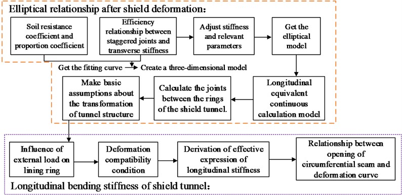
The above results are mostly analyzed from the interaction between shield machine and segment lining, tunnel displacement, deformation analysis and change rules, and less from the nature and characteristics of tunnel construction deformation. Therefore, the deformation analysis is conducted with the help of construction monitoring data in order to provide reference value from its dynamic characteristics. At the same time, in the study of tunnel deformation model, a three-dimensional tunnel model is established to analyze the efficiency relationship between staggered joint assembly and transverse stiffness, the influence of external load of lining ring and the longitudinal equivalent continuous calculation model of transverse effect. When calculating the circumferential gap model in the longitudinal structure, considering the influence of the bolt stiffness and longitudinal changes on the tunnel ring joint, and the difference between the distributed bolts and the actual bolts in the actual process, the stiffness correction factor is introduced to correct. Based on the actual stress of the shield tunnel, the deformation is simulated, analyzed and monitored in the result section. This method makes a detailed analysis of the content of the research problem, which can effectively evaluate its status correctly in the process of safe construction. Therefore, during the operation of the tunnel project, necessary internal force calculation and tunnel maintenance must be done for the tunnel structure to ensure the stable and effective operation of the tunnel project. Through the construction inspection data, the mechanical structure calculation and safety index evaluation of the longitudinal bending deformation of underground tunnels will provide important technical support for the construction and maintenance of underground tunnels in China.
3. Calculation of longitudinal deformation model of Shield tunnel
3.1. Calculation of longitudinal deformation model for transverse effect of Shield tunnel
Shield tunnel is mainly the longitudinal deformation of segment ring. For the convenience of study, the modified conventional method is used to simulate the transverse deformation of shield tunnel. This method considers the influence relationship between longitudinal joints and segment transverse performance. It also evaluates the stiffness reduction caused by segment joints as the overall bending stiffness reduction of segment ring. The bending transfer caused by joints is shown in Fig. 1.
In Fig. 1, where the bending matrix is calculated according to the full circle bending stiffness, the design bending moment of the main section is . The bending moment increase rate, the design bending moment of the segment is .
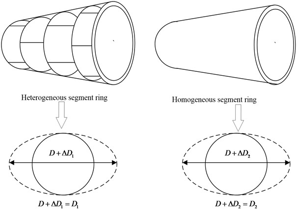
In the calculation of the transverse stiffness effect of shield tunnel, it is composed of segment blocks in the transverse direction and lining rings in the longitudinal direction. Therefore, the longitudinal performance of the tunnel is limited, and the transverse performance of the tunnel is easily constrained by the longitudinal structure. The longitudinal and transverse stress belong to a linear relationship. So, the theoretical calculation of lateral stiffness effect is realized by using the modified idiom and combined with the calculation model of lateral performance of shield tunnel. If the increase coefficient of staggered joint assembly stiffness is set as , the transverse equivalent stiffness is shown in Eq. (1) [28]:
where, is the tunnel diameter. is the diameter variable. is the actual bending stiffness of the segment ring, and is the equivalent bending stiffness of the homogeneous segment ring. Fig. 2 shows the comparative calculation diagram of transverse stiffness efficiency of segment ring of shield tunnel.
Fig. 1Bending transmission caused by joint
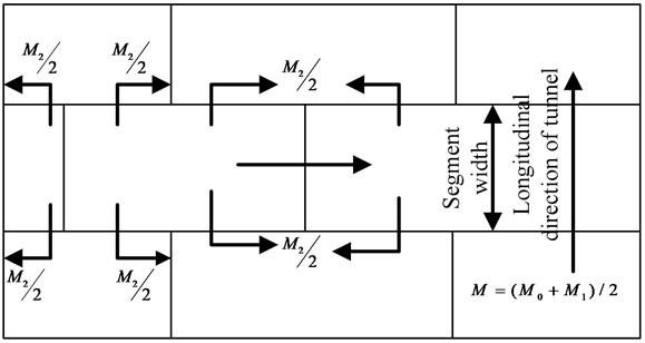
Fig. 2The calculation diagram of effective lateral stiffness of shield tunnel ring
When discussing the relationship of ellipse after shield deformation, it is considered that the soil resistance coefficient and the proportion coefficient are linear. And then the fitting curve expression can be obtained, as shown in Eq. (2):
By establishing a three-dimensional model of the underground tunnel, the efficiency relationship between staggered joint assembly and transverse stiffness was obtained. The circumferential staggered joint increases the transverse stiffness by 17.5 %. Considering the influence of staggered joint and longitudinal joint, the stiffness efficiency is 0.71. If it brings the relevant parameters into Eq. (2) and normalize the water gravity, the tunnel will appear oval as Eq. (3):
where, is the gravity of water, is the reaction coefficient. is the long radius of ellipse after tunnel deformation, is the short radius after tunnel ellipse deformation, is the diameter before tunnel deformation, is the diameter after deformation; and is the Poisson’s ratio of soil layer. Based on the derivation of the segment of the shield tunnel, the radial base reaction coefficient of the single ring is obtained, as shown in Eq. (4):
where, represents the elastic modulus of surrounding rock formation. Bringing Eq. (4) into Eq. (3) can obtain the expression relationship of tunnel elliptical deformation, as shown in Eq. (5):
In the study of tunnel deformation model, it is also necessary to consider the longitudinal equivalent continuous calculation model of the transverse effect. First, the calculation of the joint between the rings of the shield tunnel sets the length in the center line of the two adjacent segments as . If the shield tunnel is affected by the longitudinal bending moment , the relative rotation angle between the adjacent segments at the joint is , and the theoretical curvature of the beam bending is . To further discuss the relationship between the stress and deformation of the lining ring, it is necessary to make basic assumptions about the transformation of the tunnel structure. At the same time, because the ratio of the thickness of the lining ring to the diameter of the tunnel is very small, the influence of its change is not considered in the calculation. As the expression of the average linear stiffness of the lining ring joint bolt structure is obtained through assumptions, as shown in Eq. (6):
where, represents the sum of elastic stiffness coefficients of circumferential joints, represents the total number of longitudinal bolts, represents the elastic stiffness coefficient of a single bolt, represents the transverse sectional area of the lining ring. represents the center radius of the shield pipe, represents the thickness of the pipe, and represent the elastic modulus of bolts and the sectional area of bolts respectively, and represents the effective length of bolts.
In the study of longitudinal bending stiffness of shield tunnel, the longitudinal equivalent continuous model is usually used to analyze the tunnel structure. Considering the influence of transverse convergence of shield tunnel, the lining ring has elliptical deformation under the action of external force. Through the geometric relationship of the transverse deformation of the segment, the compression side below the neutral axis meets Eq. (7):
where, and are the long and short radii of the transverse section of the segment ring after deformation, is the central axis position, represents any micro unit in the segment, is the center angle of the circle, and is the distance between the neutral axis and the micro circle. The tension side above the neutral axis meets Eq. (8):
According to the elliptic parameter equation, if the coordinate parameter of any point of the circle is set as , the expression of the neutral axis position can be obtained, as shown in Eq. (9):
The stress level of the bolt under the influence of external load of the lining ring is relatively low, which is significantly lower than the yield strength. The bolt maintains an elastic state. Through the deformation analysis of the tunnel ring joint, the expression of Eq. (10) can be obtained from the deformation coordination condition:
In Eq. (10), represents the maximum cracking amount of the replacement joint, represents the tensile stress of the segment, and represents the compressive stress of the segment. Considering the bending stress of the lining ring, if its tensile force is equal to the tensile force of the joint, there is an equilibrium condition, as shown in Eq. (11):
Eq. (12) is obtained by converting Eq. (10) and Eq. (11):
Eq. (13) is obtained by introducing the equivalent ring stiffness Eq. (6) into Eq. (12):
In Eq. (13), represents the transverse surface area of the lining segment, and represents the elastic modulus of the segment. The structural relationship between the neutral axis and the lining segment can be known from Eq. (13) which determines the position relationship of the neutral axis. The expression obtained from the balance formula of force is shown in Eq. (14):
By taking Eq. (7-10) into Eq. (14), the circumferential seam angle under longitudinal bending is obtained, as shown in Eq. (15):
At the same time, the equivalent continuous beam angle of longitudinal bending deformation is calculated according to the curvature equation, as shown in Eq. (16):
According to Eq. (14) and Eq. (15), the effective expression of longitudinal stiffness is shown in Eq. (17):
In Eq. (17), represents the inertia of the segment ring fracture surface, and represents the longitudinal isotropic stiffness. By further calculating and deriving the equation, the effective expression of longitudinal stiffness is as shown in Eq. (18):
In the study of longitudinal force of shield tunnel, the longitudinal bending deformation of tunnel is formed by the rotation between lining rings. Through Eq. (10) and (16) and the plane curvature of longitudinal bending deformation, the relationship between the opening of segment circumferential seam and deformation curve under longitudinal deformation can be obtained. As shown in Eq. (19):
3.2. Model calculation and safety evaluation of circumferential seam opening in longitudinal structure
The longitudinal force of shield tunnel is due to the bending deformation of tunnel structure layer. It is related to the opening of segment circular joints in the tunnel. The stiffness and longitudinal bolt directly affect the opening of tunnel annular joints. It is very important to evaluate the equivalent bolt stiffness reasonably.
For the discussion of the difference between the ring joint and the equivalent bolt ring, according to the structure and the relevant calculation theory of shield tunnel, the longitudinal bolt is generally equivalent to a stiffness ring with linear characteristics. The effectiveness of it is set to in the calculation. The shield tunnel can be a foundation beam with mean value equivalent to participate in the calculation. The calculation of the equivalent bending stiffness in the longitudinal bending direction of the tunnel mainly refers to Eq. (20). But the difference in the bolt point distribution will be ignored in the calculation, as shown in Fig. 3 [29].
Fig. 3The longitudinal bending direction of the tunnel equival bolt ring and actual bolt ring
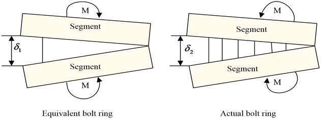
To clarify the difference between the equivalent line distribution bolt ring and the actual joint bolt in the shield tunnel segment lining, and modify the stiffness equation of the longitudinal equivalent joint bolt ring, the bending stiffness correction coefficient is introduced in the actual calculation, as shown in Eq. (20):
where, represents the maximum circumferential seam opening of the equivalent bolt ring of stiffness; and represents the circumferential seam opening of the segment corresponding to the actual point distribution joint bolt.
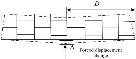
In the study of longitudinal joint model, shield tunnel was mainly composed of segment joints. Segment rings need to be connected with bolts. There was an in-depth research on segment ring structure in China, which mainly adopted the safety evaluation strategy of load structure method. The lining of subway tunnel is composed of two adjacent blocks, three standard blocks and a capping block. The load structure method is used to construct the three-dimensional diagram of shield tunnel segment lining, as shown in Fig. 4. Among them, the model segments, lining pads and joints adopt solid elements. The influence of soil layer on the tunnel can be simulated by using the foundation spring element. It can realize the mathematical calculation of the tunnel lining structure.
In the actual calculation of the model, the maximum disturbance at the midspan can be known according to the deformation curve relationship of the bending beam. The number of bolts, bolt types, lining diameter and ring width of shield tunnel are different in different environments. The equivalent stiffness correction coefficient of segment ring bolts will also be affected by the changes of external environment. Through the study of these factors, the most realistic calculation method of tunnel longitudinal deformation will be determined to effectively evaluate the safety of shield tunnel. The segment ring of the tunnel has a direct impact on the correction of the equivalent stiffness. With the increase of the segment ring thickness, the correction coefficient will also increase. From Eq. (17), the longitudinal equivalent bending stiffness of the theoretical shield tunnel is modified, as shown in Eq. (21) [30]:
Fig. 4Calculation model of tunnel lining structure
For the effective evaluation of the safety of shield tunnel, it is necessary to consider various factors and lining parameters of the tunnel to get different equivalent stiffness correction coefficients. When the correction coefficient is brought into Eq. (19), the corrected circumferential seam opening can be obtained. It is expressed in the longitudinal deformation of the tunnel, as shown in Eq. (22):
At the same time, the relationship between the stress of the longitudinal structure and the opening of the ring is studied. Considering the complex stress of the longitudinal deformation of the tunnel, the stress of the joint bolt and the opening of the longitudinal circumferential seam should be analyzed when evaluating the safety of it. The requirements of segment opening, the critical state of transverse convergence deformation and the design of lining pipe need to be fully considered. In the safety evaluation, the control index of longitudinal deformation of tunnel is selected based on the opening of segment ring of tunnel lining and the limit state of bolt stress. The index refers to the relevant technical requirements of domestic traffic safety. The longitudinal safety evaluation standard of shield tunnel is proposed. In the first level safety evaluation, the radius of curvature is 2500 m, and the opening of circumferential joint is 3 mm, which meets the design and water control requirements in all aspects. And the tunnel is free of disease. In the secondary safety evaluation, the curvature radius is 1500 m, and the opening of the circumferential seam is 6 mm. The tunnel meets the water control requirements. And the treatment of water seepage needs to be strengthened. From the third level safety evaluation, the radius of curvature is 700 m, the opening of the circumferential seam is 12 mm. The waterproof effect of the circumferential seam layer, the bolt damage, and the tunnel needs further maintenance. The calculation of the longitudinal deformation model of the transverse effect of the shield tunnel can be represented with the help of Fig. 5.
Analyzing the elliptical relationship after shield deformation and the longitudinal bending stiffness of shield tunnel can effectively modify and change the parameters, and improve the adaptability and stability of the model to the experimental data.
Fig. 5Deformation model of transverse effect of shield tunnel
4. Analysis of longitudinal deformation data of Shield tunnel
Taking a domestic adjacent tunnel construction project as the research object, the computer numerical simulation platform is used to analyze the effect of foundation pit operation on the longitudinal deformation of shield tunnel. And the numerical model is used to simulate and analyze various influencing factors of tunnel. The excavation depth of a foundation pit project is 20 m. The maximum size in the north-south direction is 16 m, and the maximum size in the east-west direction is 124 m. During the foundation pit operation, dynamic monitoring was carried out on all affected points of the subway shield tunnel. There are 9 monitoring sections near the left side of the foundation pit, and 6 monitoring points are arranged on each section. The final test results are shown in Fig. 6. The parameter design and related indicators involved in the experimental process of the study were calculated according to the proposed method, and the relevant content of document [31] was also referenced.
Fig. 6Test results of shield tunnel
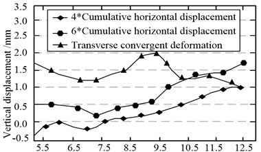
a) 1 A horizontal displacement detection of measuring point
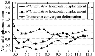
b) 12 A horizontal displacement detection of measuring point
From the test results in Fig. 6, during the construction of foundation pit, the shield tunnel will be displaced in the direction of foundation pit construction. Fig. 6(a) shows the displacement results of 1 A monitoring section. The overall maximum horizontal displacement detected on day 1 was 1.7 mm of monitoring point 4*. At the same time, according to the displacement difference between 4* and 6* to be measured, the maximum convergence change of this section was 2.0 mm. In Fig. 6(b), the displacement of tunnel at 12 A monitoring section is shown. For the tunnel far away from the foundation pit, the maximum displacement was –0.8 mm, and the horizontal convergence change was 3.5 mm at this moment. Day 47, it was detected that the overall maximum horizontal displacement was 0.5 mm of the detection point 4*. Compared with figure (a) and figure (b), section 1 A is closer to the tunnel, and the horizontal interference of the tunnel is higher than that of 12 A. At the same time, the foundation pit operation is gradually away from the tunnel. The impact of shield tunnel is gradually reduced. As shown in Fig. 7, the vertical displacement of the tunnel changes.
Fig. 7Effect of foundation pit operation on vertical displacement of tunnel
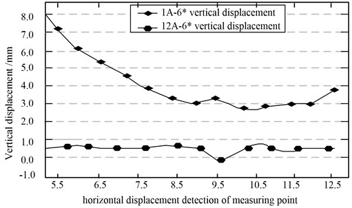
Fig. 8Effect of foundation pit operation on vertical displacement of tunnel numerical results of horizontal displacement of segments
a) 1 A horizontal displacement of left and right lines
b) 12 A horizontal displacement of left and right lines
Fig. 7 shows the vertical displacement change of the tunnel. The foundation pit construction operation leads to the soil rebound, which causes the vertical displacement of the shield tunnel. Since the 1A measuring point is closer to the tunnel, its maximum vertical displacement is 8 mm. While 12 A is 8.25 m away from the tunnel, its maximum vertical displacement is 0.8 mm, which has little impact on the tunnel as a whole.
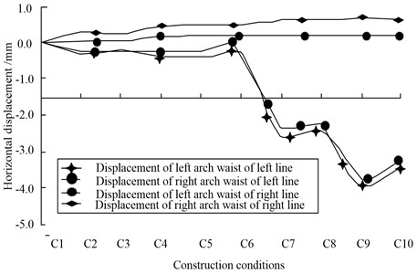
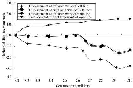
To further discuss the influence of foundation pit operation on metro shield tunnel, midas/gts calculation platform will be used for three-dimensional numerical analysis. In the construction inspection data, two ring segment linings with different sections were selected for analysis, namely segment ring 1 A near the tunnel and segment ring 12 A away from the tunnel. The data model results were shown in Fig. 8.
Fig. 8 shows the numerical results of segment horizontal displacement, in which C1-C10 is the working condition of foundation pit. It will affect the horizontal displacement of the tunnel and the transverse deformation of the section. Fig. 8(a) shows the operation position of 1 A tunnel segment ring foundation pit. The displacement of the left and right tunnels is basically the same, in which the maximum horizontal displacement of the left line tunnel is –3.8 mm, and the right line tunnel is 3.7 mm. Fig. 8(b) shows the operation position of 12 A tunnel segment ring foundation pit. 12 A is far away from the tunnel, and there is an obvious difference between the displacement of the left and right ring tunnels. The maximum horizontal displacement of the left line tunnel is –3.1 mm, and the right line tunnel is 1.8 mm. However, the transverse section of the tunnel location is basically the same. The transverse deformation value of the left and right tunnels is maintained at 1.5 mm. And the test prediction results are close to the average value, which shows that the model prediction results are feasible. At the same time, working condition C8 is selected as the research object to test the vertical displacement of the left and right vaults of the tunnel, as shown in Fig. 9.
Fig. 9Vertical displacement of left and right vault of tunnel
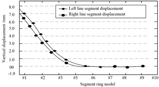
From the test data in Fig. 9, considering the construction spacing of foundation pit, there is a great difference in the numerical displacement of left and right vault \1-\10. Among them, the left line is more affected by the foundation pit operation, and the vertical displacement increases by 1 mm compared with the right line. When the distance between the construction site and the tunnel gradually increases, convergence is obtained at #6 segment. Due to the deformation of the foundation and the change of internal stress and external load, the structure of the subway project is easy to produce structural deformation and settlement. And the excavation of the foundation pit is the main influencing factor. The disturbance caused by it will make the tunnel structure and the surrounding soil deformation uncoordinated. Its retaining structure will move toward the pit, and corresponding displacement changes will occur. The increase of excavation depth will aggravate the deformation of the retaining structure. Strengthening the real-time monitoring of the tunnel in the foundation pit can effectively analyze the stress of the structure, and effectively avoid its deformation strength exceeding its limit. Moreover, when the distance between the center lines of the foundation pit continues to expand, the relative deformation of each section will also decrease.
In the checking calculation of transverse convergence deformation theory, the foundation pit is taken as the experimental object through the calculation method of circumferential seam opening model of longitudinal structure. Finally, the maximum transverse convergence deformation of the tunnel is 3.5 mm, and the average value is 28 mm. Although the calculation results are different from the theoretical results and the detection data is relatively large, they basically meet the actual requirements, and are calculated through the data in Table 1. The reason for large deformation monitoring data may be that the soil geology of the project is soft. So its settlement is obvious and easy to increase the amount of data testing.
Table 1Partial parameter information of shield tunnel lining structure
Parameter information | Specific quantity |
Internal diameter (m) | 5.4 |
External diameter (m) | 6 |
Concrete elastic formwork (Kpa) | 3.45×10⁷ |
Ring width (m) | 1.5 |
Ring thickness (m) | 0.3 |
Bolt length (mm) | 400 |
Bolt diameter (mm) | 27 |
Bolt quantity (individual) | 10 |
From Table 1 partial parameter information of shield tunnel lining structure, through data calculation, the effective stiffness is 0.047. In the shield tunnel, the transverse elliptical effect of the tunnel will affect the longitudinal stiffness. The longitudinal bending stiffness of the tunnel is reduced by 24 %. At the same time, the monitoring data of D6 and D7 sections of the subway tunnel are selected for safety evaluation, and the transverse convergence deformation theory is used for checking calculation. The equivalent bolt stiffness of segment ring is 3.46×10⁵ Kpa. The neutral axis position is , and the longitudinal equivalent bending stiffness is 3.47×10⁷ KN.m2. By querying the stiffness correction value, is brought into Eq. (21) to obtain correction 3.87×10⁷ KN.m2. The shield tunnel often produces longitudinal deformation due to external disturbance. The main factor causing the longitudinal deformation of the tunnel is the opening of the circumferential seam, which will be affected by the stiffness of the circumferential seam bolt. The stiffness coefficient of bolt ring will be affected by many factors, internal factors such as the number and type of bolts, and external factors such as the strength of soil layer and the interference degree of external environment. The larger the stiffness coefficient of the actual joint bolt ring, the greater the equivalent bolt stiffness error will be caused by it. It is proposed that the correction coefficient is used to correct the circumferential deformation gap, and then its segment ring thickness and bolt is increased. It effectively reduces the error increase caused by the rigidity bending under the longitudinal deformation of the tunnel. Through correcting and calculating the relevant data, the longitudinal deformation curvature radius and the theoretical maximum opening of the shield tunnel are finally obtained. The data are shown in Table 2.
Table 2Radius of curvature and theoretical maximum opening of longitudinal deformation of tunnel
Tunnel circumferential joint | Radius of curvature (mm) | Opening amount (mm) |
Opening amount (mm) | 8145 | 0.9 |
Left line #7 | 15486 | 0.5 |
Right line #8 | 758 | 8.8 |
Right line #6 | < 37056 | 0.2 |
Table 2 the final opening calculation results show that the radius of curvature of the annular segment and the opening of the circumferential seam at the tunnel connection are larger than those in other areas. At the same time, the tunnel connection is also the area with the most serious longitudinal deformation. In the right line tunnel, the curvature radius and opening of segment ring are 876 mm and 8.9 mm respectively, which exceed the level II longitudinal deformation safety assessment. Safety assessment refers to the comprehensive evaluating and predicting of potential risks and possible consequences of the proposed or existing projects and systems by using the principles and methods of system engineering. Corresponding safety countermeasures are put forward according to the magnitude of the possible accident risks to achieve the project and system safety. The tunnel lithology, soil structure, the variability of structural system parameters, internal and external environmental pressure, sudden natural disasters, etc. will bring different degrees of hazards to the tunnel safety, and the higher its safety assessment, the higher its service life and reliability of operation. The common risks are mostly evaluated according to the Provisional Regulations on Risk Assessment and Management of Railway Tunnels and the Code for Design of Building Foundation. The building risk caused by tunnel construction is generally divided into four levels. However, due to the waterproof treatment of the tunnel, it meets the third level safety assessment (700 mm). The detection points should be added around the tunnel and foundation pit, and the fixed point detection of the waterproof area should be strengthened to ensure the stability of the structure in the area.
5. Conclusions
Compared with other construction technologies, shield tunnel can effectively avoid the construction interference of unfavorable geology such as water sand layer and high water pressure layer. But its excavation construction efficiency is easily affected by mud fluidity and water stop. Its support structure is prone to longitudinal deformation due to internal and external force under earth pressure. Therefore, based on the monitoring of shield construction, the transverse and longitudinal deformation of the tunnel was discussed. The calculation model of internal force and circumferential gap of the tunnel structure was built. The experimental results showed that the shield displacement caused by the calculation model in the vertical displacement of the tunnel under a certain working condition has a small impact. The numerical deviation of the left and right line tunnel displacement under the working and operating position of the annular foundation pit in the tunnel section was small. The cross section of the tunnel location was basically the same. The lateral deformation value of the left and right line tunnels was maintained at 1.5 mm. And when the distance between the construction site and the tunnel increases gradually, the relative deformation of each section of the foundation pit will decrease. The maximum transverse convergence deformation calculated by the circumferential gap model of the longitudinal structure was 3.5 mm. It basically meets the practical requirements. The safety assessment of the area with the most serious longitudinal deformation at the tunnel junction after treatment also meets the Class III standard (700 mm). This method can effectively provide reference value for tunnel deformation and safe construction. But the correction coefficient proposed for the bending stiffness of the tunnel is only suitable for working conditions at the operation stage. Therefore, strengthening the influence between the tunnel and the lining, and zoning the tunnel construction deformation are the key content that needs to be improved in the future.
References
-
F. Xue and M. Zhang, “Failure mode and stability of excavation face on shield tunnel undercrossing existing tunnel,” Civil Engineering Journal, Vol. 5, No. 9, pp. 2070–2080, Sep. 2019, https://doi.org/10.28991/cej-2019-03091394
-
D. M. Ai, C. X. Lin, H. Luo, and H. P. Zhu, “Temperature effect on electromechanical admittance-based concrete structural health monitoring,” Structural Health Monitoring, Vol. 19, No. 3, pp. 661–692, 2020.
-
M.M. Ayasrah, H. Qiu, X. Zhang, and M. Daddow, “Prediction of ground settlement induced by slurry shield tunnelling in granular soils,” Civil Engineering Journal, Vol. 6, No. 12, pp. 2273–2289, Nov. 2020, https://doi.org/10.28991/cej-2020-03091617
-
M.-G. Li, J.-J. Chen, J.-H. Wang, and Y.-F. Zhu, “Comparative study of construction methods for deep excavations above shield tunnels,” Tunnelling and Underground Space Technology, Vol. 71, No. 1, pp. 329–339, Jan. 2018, https://doi.org/10.1016/j.tust.2017.09.014
-
M. Yin, H. Jiang, Y. Jiang, Z. Sun, and Q. Wu, “Effect of the excavation clearance of an under-crossing shield tunnel on existing shield tunnels,” Tunnelling and Underground Space Technology, Vol. 78, No. 1, pp. 245–258, Aug. 2018, https://doi.org/10.1016/j.tust.2018.04.034
-
Z. Huang, H. Fu, W. Chen, J. Zhang, and H. Huang, “Damage detection and quantitative analysis of shield tunnel structure,” Automation in Construction, Vol. 94, No. 1, pp. 303–316, Oct. 2018, https://doi.org/10.1016/j.autcon.2018.07.006
-
Y. Xue and Y. Li, “A Fast Detection Method via Region‐Based Fully Convolutional Neural Networks for Shield Tunnel Lining Defects,” Computer-Aided Civil and Infrastructure Engineering, Vol. 33, No. 8, pp. 638–654, Aug. 2018, https://doi.org/10.1111/mice.12367
-
K. Elbaz, S.-L. Shen, W.-J. Sun, Z.-Y. Yin, and A. Zhou, “Prediction Model of Shield Performance During Tunneling via Incorporating Improved Particle Swarm Optimization Into ANFIS,” IEEE Access, Vol. 8, pp. 39659–39671, 2020, https://doi.org/10.1109/access.2020.2974058
-
Y.-M. Ryu, Y.-S. Kwon, T.-H. Kim, and I.-M. Lee, “Slurry clogging criteria for slurry shield tunnelling in highly permeable ground,” KSCE Journal of Civil Engineering, Vol. 23, No. 6, pp. 2784–2793, Jun. 2019, https://doi.org/10.1007/s12205-019-2156-x
-
R. Rui, C. Cheng, and Y. X. Zhai, “Model tests on earth pressure and settlement of shield tunnel crossing adjacent underground retaining structures,” Yantu Gongcheng Xuebao/Chinese Journal of Geotechnical Engineering, Vol. 42, No. 5, pp. 864–872, 2020.
-
K. Tsuno, K. Kinoshita, and T. Ushida, “Investigation of Deformation of Shield Tunnel Based on Large-scale Model Test,” Quarterly Report of RTRI, Vol. 61, No. 1, pp. 16–21, Feb. 2020, https://doi.org/10.2219/rtriqr.61.1_16
-
X. W. Gao, M. Jian, M. Hu, M. Tanniru, and S. Q. Li, “Faster multi-defect detection system in shield tunnel using combination of FCN and faster RCNN,” Advances in Structural Engineering, Vol. 22, No. 13, pp. 2907–2921, 2019.
-
Y. Fu, F. Wang, C. Hong, J. Wen, and D. Zeng, “A simplified deformation forewarning method for longitudinal structural performance of existing shield tunnels based on fast Fourier transform,” Tunnelling and Underground Space Technology, Vol. 131, p. 104813, Jan. 2023, https://doi.org/10.1016/j.tust.2022.104813
-
J. Zhang, C. He, P. Geng, Y. He, and W. Wang, “Improved longitudinal seismic deformation method of shield tunnels based on the iteration of the nonlinear stiffness of ring joints,” Sustainable Cities and Society, Vol. 45, pp. 105–116, Feb. 2019, https://doi.org/10.1016/j.scs.2018.11.019
-
H. Luo, L. Li, and K. Chen, “Parametric modeling for detailed typesetting and deviation correction in shield tunneling construction,” Automation in Construction, Vol. 134, p. 104052, Feb. 2022, https://doi.org/10.1016/j.autcon.2021.104052
-
Z. Zhang, W. Wo, L. Mu, J. Chen, Z. Zhu, and Y. Pan, “Mathematical modelling for shield tunneling induced displacement effects on in-service tunnel: Theoretical solution including shearing deformation of segment and stiffness reduction of circumferential joints,” Applied Mathematical Modelling, Vol. 118, pp. 322–345, Jun. 2023, https://doi.org/10.1016/j.apm.2023.01.031
-
S. Fan, Z. Song, T. Xu, K. Wang, and Y. Zhang, “Tunnel deformation and stress response under the bilateral foundation pit construction: A case study,” Archives of Civil and Mechanical Engineering, Vol. 21, No. 3, pp. 1–19, Aug. 2021, https://doi.org/10.1007/s43452-021-00259-7
-
S. Bhamidipati, K. J. Kim, H. B. Sun, and P. V. Orlik, “Artificial-intelligence-based distributed belief propagation and recurrent neural network algorithm for wide-area monitoring systems,” IEEE Network, Vol. 34, No. 3, pp. 64–72, 2020.
-
X. Zhang and G. Chen, “An automatic insect recognition algorithm in complex background based on convolution neural network,” Traitement du Signal, Vol. 37, No. 5, pp. 793–798, Nov. 2020, https://doi.org/10.18280/ts.370511
-
Z. Xia, J. Xing, C. Wang, and X. Li, “Gesture recognition algorithm of human motion target based on deep neural network,” Mobile Information Systems, Vol. 2021, No. 3, pp. 1–12, Jul. 2021, https://doi.org/10.1155/2021/2621691
-
S. P. Parida and P. C. Jena, “Selective layer-by-layer fillering and its effect on the dynamic response of laminated composite plates using higher-order theory,” Journal of Vibration and Control, Vol. 29, No. 11-12, pp. 2473–2488, Jun. 2023, https://doi.org/10.1177/10775463221081180
-
S. P. Parida and P. C. Jena, “Free and forced vibration analysis of flyash/graphene filled laminated composite plates using higher order shear deformation theory,” Proceedings of the Institution of Mechanical Engineers, Part C: Journal of Mechanical Engineering Science, Vol. 236, No. 9, pp. 4648–4659, 2022.
-
S. P. Parida and P. C. Jena, “Advances of the Shear Deformation Theory for Analyzing the Dynamics of Laminated Composite Plates: An Overview,” Mechanics of Composite Materials, Vol. 56, No. 4, pp. 455–484, Sep. 2020, https://doi.org/10.1007/s11029-020-09896-0
-
P. C. Jena, D. R. Parhi, and G. Pohit, “Dynamic investigation of FRP cracked beam using neural network technique,” Journal of Vibration Engineering and Technologies, Vol. 7, No. 6, pp. 647–661, Dec. 2019, https://doi.org/10.1007/s42417-019-00158-5
-
S. P. Parida and P. C. Jena, “Design and finite element analysis of thick walled laminated composite pressure vessel,” International Journal of Innovative Technology and Exploring Engineering, Vol. 8, No. 10, pp. 4389–4394, 2019.
-
P. C. Jena, D. R. Parhi, and G. Pohit, “Fault measurement in composite structure by fuzzy-neuro hybrid technique from the natural frequency and fibre orientation,” Journal of Vibration Engineering and Technologies, Vol. 5, No. 2, pp. 124–136, 2017.
-
S. P. Parida, P. C. Jena, and R. R. Dash, “Dynamics of rectangular laminated composite plates with selective layer-wise fillering rested on elastic foundation using higher-order layer-wise theory,” Journal of Vibration and Control, Nov. 2022, https://doi.org/10.1177/10775463221138353
-
W. Yang, J. Zheng, R. Zhang, and H. Liu, “An empirical model for characterizing 3D deformation at the face of shield tunnel in soft clay,” Tunnelling and Underground Space Technology, Vol. 112, p. 103862, Jun. 2021, https://doi.org/10.1016/j.tust.2021.103862
-
P. Lou, Y. Li, S. Lu, H. Xiao, and Z. Zhang, “Deformation and mechanical characteristics of existing foundation pit and tunnel itself caused by shield tunnel undercrossing,” Symmetry, Vol. 14, No. 2, p. 263, Jan. 2022, https://doi.org/10.3390/sym14020263
-
F. Wang, J. Shi, H. Huang, and D. Zhang, “Modified analytical solution of shield tunnel lining considering nonlinear bending stiffness of longitudinal joint,” Tunnelling and Underground Space Technology, Vol. 106, p. 103625, Dec. 2020, https://doi.org/10.1016/j.tust.2020.103625
-
D. Liu, C. Tian, F. Wang, Q. Hu, and J. Zuo, “Longitudinal structural deformation mechanism of shield tunnel linings considering shearing dislocation of circumferential joints,” Computers and Geotechnics, Vol. 139, p. 104384, Nov. 2021, https://doi.org/10.1016/j.compgeo.2021.104384
About this article

The authors have not disclosed any funding.
The datasets generated during and/or analyzed during the current study are available from the corresponding author on reasonable request.
The authors declare that they have no conflict of interest.
