Abstract
Taking the shield tunnel project of Guangzhou Metro Line 8 from Tongdewei Station to Shangbu Station as the research background, using the research method of finite element simulation and site monitoring, this paper analyses the influence rules of shield tunneling on ground subsidence under the condition of different hard rock height ratios. The research results show that in the process of crossing different hard rock height ratio composite stratum, as the hard rock height ratio decreases, the value of ground settlement decreases and settlement tank becomes shallow. The surface subsidence in different hard rock height ratio strata is obviously different, and the maximum difference is about 8.6 mm; The influence of the hard rock height ratio on the surface longitudinal settlement is mainly reflected in the position change of the beginning and the end of the settlement. With the increase of the hard rock height ratio, the shield construction reduces the amount of the surface longitudinal settlement and its influence range; Through the research, it is found that the hard rock height ratio in the 0-0.2 and 0.5-1 is the sensitive interval, and the settlement value in these two hard rock height ratio interval varies greatly. It is necessary to pay attention to the uneven settlement of the ground surface caused by shield construction in the sensitive hard rock height ratio interval. The research results of this paper can provide reference value for similar shield construction in upper soft and lower hard composite stratum.
1. Introduction
Traffic construction in major cities has increasingly become prominent with rapid urbanization. Urban rail transit construction (dominated by subways) has been conducted in the infrastructure of large cities in China in recent years to alleviate the increasingly heavy traffic problems. Shield tunneling is widely used in urban underground rail transit construction because of its safety and small impact on the stratum and surrounding environment. However, stratum disturbance is inevitable during shield construction, which causes the uplift and subsidence of disturbed soil and even cracking of buildings or damage of underground pipelines [1-5]. Experts and scholars at home and abroad have conducted extensive research on the impact of shield construction [6-10]. Stratum deformation caused by the construction of urban metro tunnels was reported in 1960s. In 1969, Peck [11] proposed a Gauss equation to predict the stratum deformation caused by shield tunneling. Subsequently, scholars at home and abroad have performed considerable theoretical research, numerical simulation, and model testing related to this problem [12-16]. Liu [17] established the original Peck formula. On this basis, consolidation settlement caused by the dissipation of excess pore water pressure was considered, and a formula for estimating the surface vertical and horizontal settlements through formation loss was presented. In practical engineering, the factors affecting stratum subsidence are extremely complex, and subsidence trough and settlement curve of stratum change accordingly [18-21].
China has a vast territory and varying geological conditions. Its upper-soft and lower-hard strata are widely distributed in the coastal areas of Guangzhou, Shenzhen, and Fuzhou and they are typical geological conditions in urban rail transit. The engineering characteristics of upper-soft and lower-hard strata have huge difference in physical and mechanical properties between rock and soil and sensitive response to external disturbances [22-24]. During the construction of metro shield in such special strata, the upper-soft soil can be easily over excavated, causing immense stratum disturbance; moreover, this soil cannot form a stable pressure arch effect [25-28], which will cause abnormal movement of the excavated surface soil, large-scale collapse of the soft soil stratum, deviation of the shield driving angle from the predetermined value, and the occurrence of surface subsidence. Large-scale settlement remarkably challenges shield tunnel construction. Therefore, the influence of shield tunneling on strata under the condition of upper-soft and lower-hard composite strata should be investigated [29-33]. Deng et al. [34] took Shenzhen Metro Line 2 as an engineering example, conducted a construction risk analysis under the conditions of upper-soft and lower-hard composite strata, and obtained the specific tunneling parameters through slag soil improvement and tool change with pressure; consequently, they provided valuable data for the theoretical study of shield tunneling under complex geological conditions. Wang et al. [35] conducted indoor model testing and numerical simulation to evaluate the over-excavation phenomenon of soft soil and disturbance characteristics in the upper-soft and lower-hard composite strata of EPB shield. The study provided certain reference value for the construction tools of EPB shield in the upper-soft and lower-hard strata. Wuke et al. [36] took Shenzen Metro Line 7 as an engineering example and established a three-dimensional finite element model of the existing urban road crossing under the condition of upper-soft and lower-hard strata. The numerical simulation results were compared with the field monitoring and measurement results, and the deformation and failure law of the existing urban road crossing under the condition of upper-soft and lower-hard strata were analyzed. The optimum construction method and corresponding support were also summarized. Yang et al. [37] evaluated the influence of upper-soft and lower-hard strata on the stability of tunnel surrounding rock. Physical experiments and numerical simulations were conducted for tunnel excavation in inclined upper-soft and hard strata. Moreover, the evolution law and distribution characteristics of stress, displacement, and failure of surrounding rock were analyzed. Wang et al. [38] performed numerical simulation to simulate the main tunnel construction in the upper-soft and lower-hard strata of a provincial hospital station in Guiyang Metro Line 2. The advantages of main support arch cover in settlement control, plastic zone distribution, and support structure safety were analyzed, and the underlying surrounding rock grade range suitable for the main support arch cover was presented. The aforementioned studies revealed the mechanism of shield tunneling in the upper-soft and lower-hard strata, which provide a certain reference value for follow-up studies. However, the research results have certain limitations due to the difference of geological conditions between the upper-soft and lower-hard composite strata and the complexity of the actual construction. The present study divides the different hard rock height ratios along the upper-soft and lower-hard composite strata of the shield tunnel project of Tongdewei-Shangbu Station of Guangzhou Metro Line 8. The influence law of shield tunnel construction on ground settlement under different hard rock height ratios is obtained through statistical analysis of field settlement data and finite element numerical simulation analysis. Some suggestions are presented on the basis of the actual construction requirements, and the research results can serve as reference for similar projects.
2. Prediction theory of surface subsidence
2.1. Prediction theory of surface transverse settlement
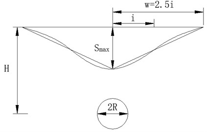
Peck believed that ground subsidence caused by construction occurs without drainage; thus, the volume of settlement trough should be equal to the volume of stratum loss. On this basis and combined with a large number of measured data, Peck proposed a method for estimating ground subsidence caused by shield tunneling in the construction stage. This method assumes that ground loss is uniformly distributed in tunnel length, the lateral distribution of ground subsidence is similar to a normal distribution curve, and its prediction method is expressed as follows [11]:
where is the ground settlement value at the central axis of the tunnel; is the maximum ground settlement value at the central line of the tunnel; is the width coefficient of the ground settlement trough, that is, the distance between the central point of the tunnel and the reverse bending point of the settlement curve; is the bottom layer loss of the unit length of the tunnel caused by excavation, that is, the volume difference between the actual excavation volume of tunnel construction and the volume after tunnel completion; is the loss rate of stratum volume; is the calculated tunnel radius; denotes the tunnel depth; and is the friction angle in soil.
As shown in Fig. 1, the ground loss is the difference between the actual excavated soil volume and the completed tunnel volume in shield tunneling. The volume of completed tunnel includes the volume of pressed slurry wrapped around the tunnel. The formation loss rate is expressed as , which is a percentage of the theoretical discharge volume of shield tunneling. The theoretical discharge volume of the circular shield is , where is the advancing length; and the formation loss per unit length is . The surrounding soils move and cause land subsidence to compensate for the stratum loss. As shown in the figure, the area of the settlement trough is equal to formation loss per unit length of the tunnel.
Fig. 1Transverse land subsidence curve
2.2. Prediction theory of longitudinal surface settlement
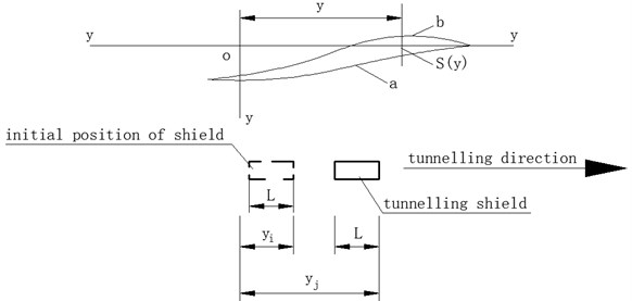
The ground settlement curve along the arch roof of the longitudinal tunnel is shown in Fig. 2. The estimation formula of settlement at a certain point is expressed as follows [11]:
where is the settlement (m) distributed along the arch roof of a longitudinal tunnel, in which negative and positive values denote the uplift and settlement values, respectively; is the distance from the settlement point to origin o of the coordinate axis (m); is the distance (m) from the excavation surface of the shield to origin of the coordinate axis at the starting point of shield driving; is the distance (m) between the shield excavation surface and the coordinate axis origin o; is the shield length (m); ; ; represents the ground loss caused by shield excavation (m8/m; for example, under-excavation of shield causes negative formation loss, and is negative); and is the formation loss (m8/m). Behind the shield excavation face, the formation loss (m8/m) caused by all construction factors, such as insufficient grouting in the shield tail clearance and the change of shield driving direction, is always positive.
When is negative, the results calculated by Eq. (2) are expressed as follows. In front of the shield tail, a certain range of points on the ground surface uplift shows an uplift curve and becomes a settlement curve in the back of the uplift curve (Fig. 2). Eq. (2) is basically applicable to the normal and uniform construction conditions of shield front and tail ground loss. If the shield front under-excavation varies uncertainly, then the Grouting is delayed, the grouting volume varies uncertainly, and the actual settlement curve does not conform to the calculation curve.
Fig. 2Longitudinal land subsidence curve
3. Engineering background and layout of measuring points
3.1. Project survey
The north extension project of Guangzhou Metro Line 8 (Cultural Park-Baiyun Lake) is an underground line that is approximately 16.3 km long. The shield tunneling section between Tongdewei Station and Shangbu Station is located in the middle of the entire line. The section line is spread from south to north along the east side of Xichao Road viaduct after Tongdewei Station. The line is mainly located along the lower side of Xichao Road. Left-line starting and closing mileage is ZDK21+078.150-ZDK21+694.400, right-line starting and closing mileage is YDK21+078.150-YDK21+694.400, and the interval length is 616.25 m. The roof depth of the tunnel structure is approximately 10-16 m, and the elevation is –2.40-7.40 m. The inner diameter of the tunnel is 5400 mm, and the thickness of the segment is 300 mm. The entire ring of the shield segment is divided into six parts, namely, three standard A-shaped segments, two adjacent C-shaped segments, and one K-shaped segment. Shield tunneling is used in this section.
3.2. Engineering geological conditions
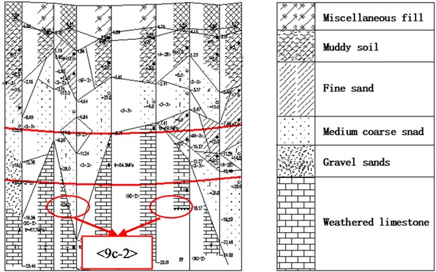
On the basis of the stratum data presented by boreholes, such as geological age, genetic type, lithological characteristics, weathering degree, and other engineering characteristics of strata, the rock and soil layers along the line are divided into four categories, namely, artificial filling layer, alluvial-diluvial layer, residual layer, and rock weathering zone. The sublayers in each layer are subdivided on the basis of their geological conditions. In this area, the hard rock surface immensely fluctuates, and the soft strata above the rock surface are thick. The main soil and rock layers in the small spacing section of shield tunneling are <1> artificial fill, <4-2> silty soil, <3-1> silty sand, <3-2> medium-coarse sand, <3-3> gravel sand, and <9C-2> slightly weathered limestone. Most of the tunnel bodies have grade VI surrounding rocks and sand, and soft soil is developed above the roof. The local floor has slightly weathered limestone intruding into the tunnel. The strength of slightly weathered limestone is high, and the tunnel section is soft and hard. For shield tunneling, the lower-hard rock has better self-stability, the upper-soft rock has poor self-stability, and the phenomenon of soft-hard unevenness is obvious because the hard rock only appears in the lower half of the excavation face. The cross section of shield tunnel needs to pass through the composite strata with different composite height ratios of hard and soft rocks. The engineering geological conditions in this area are poor. The geological profile of the left tunnel is shown in Fig. 3. The proportion of hard rock in the tunnel face is between 0 and 1.
Fig. 3Geological profile
3.3. Concept of hard rock height ratio
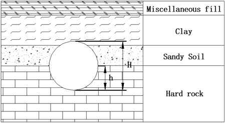
The north extension section of Guangzhou Metro Line 8 is composed of upper-soft and lower-hard strata. The properties of the overlying soil layer of shield tunnel are basically the same; however, the hard rock along the tunnel is fluctuating, which leads to different hard rock proportions along different excavation faces. Hard rock height ratio is defined as the ratio of hard rock height to the excavation surface height of shield tunnel along the line:
where is the height ratio of hard rock to stratum, is the height of soft rock, and is the total height of the tunnel excavation face.
Fig. 4Composite stratum of upper shield tunneling interval
4. Monitoring and analysis of surface subsidence
4.1. Burying of datum point and working base point for settlement monitoring
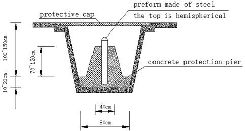
Firstly, level control point of pile crossing and encrypted level control point are used as datum points for surface settlement monitoring, and the working base points for settlement monitoring are buried outside the three times buried depth of the tunnel and not affected by shield construction. The working base points are laid in groups of 2-3 each. The absolute elevation is obtained by combined measurement of working base point and level control point after burial. The datum point adopts stainless steel measuring nails, and the embedding diagrams are shown in Figs. 5 and 6. The working base point shall be arranged in a proper range along the direction of the tunnel, and the existing and fixed points nearby shall be used as much as possible.
Fig. 5Buried drawing of level control point (hardened stratum)
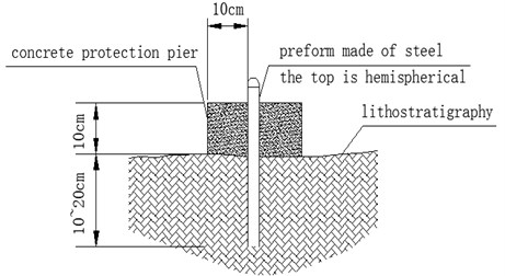
Fig. 6Buried drawing of level control point (soil layer)
4.2. Settlement monitoring point arrangement
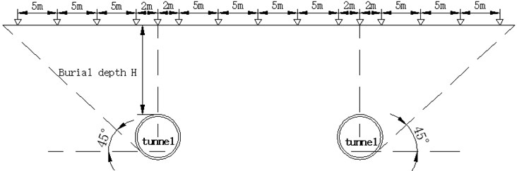
On the basis of comprehensive considering the surrounding environment grade and the operability of monitoring implementation in Tongdewei-Shangbu Station, ground settlement monitoring in shield tunneling interval can be divided into longitudinal monitoring and lateral monitoring. Longitudinal monitoring points are installed every 5 m along the middle line of the tunnel. Lateral monitoring is distributed from the center of the shield vault to both sides, from near to far, and increases by 3-5 m between the measuring points. The detailed layout are shown in Figs. 7 and 8.
Fig. 7Schematic layout of land subsidence monitoring points
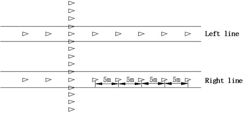
Fig. 8Cross-section layout of land subsidence monitoring points
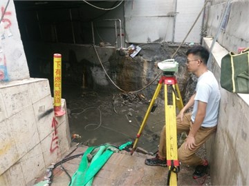
Burying monitoring points on hardened surface: firstly, drill a hole with diameter of 70 mm in hardened road surface with core pulling machine, and then drill a round head steel bar with length of 400-1000 mm and diameter of 12-20 mm into the hole. The head of the steel bar shall be 50 mm lower than the road surface, and the bottom shall be embedded in the undisturbed soil of the subgrade base, and then the sand shall be backfilled in the hole, and the steel bar shall be exposed to the sand surface for 20 mm. The embedding diagram is shown in Fig. 9. Burying monitoring points on the unhardened surface: Directly driving a round head steel bar with length of 400-1000 mm and diameter of 12-20 mm into the undisturbed soil. The steel bar shall be exposed to the surface for 50 mm, and the surrounding of the monitoring point is protected by bricklaying. The field monitoring is shown in Fig. 10.
Fig. 9The buried schematic diagram of the ground settlement monitoring points (hardened surface)
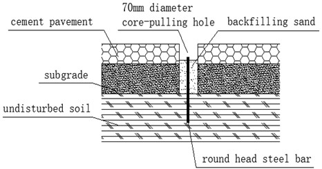
Fig. 10Field monitoring
4.3. Monitoring and analysis of surface settlement
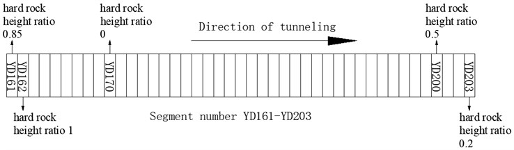
The tunnel in this shield zone is located in the upper-soft and lower-hard composite stratum. The depth of shield tunnel is approximately 14 m. The overlying soil is clay and sandy soil. The properties of the overlying soil are basically the same. However, the hard rock height ratio of the shield tunnel excavation surface changes due to the fluctuation of the hard rock surface along the line. To determine the relationship between the hard rock height ratio of excavation face and surface subsidence, five sections with different hard rock height ratios along the line are selected for monitoring on the basis of the results of geotechnical investigation report and field investigation. The segment numbers corresponding to the five typical sections are YD170 (hard rock height ratio 0), YD 203 (hard rock height ratio 0.2), YD 200 (hard rock height ratio 0.5), YD 161 (hard rock height ratio 0.85) and YD 162 (hard rock height ratio 1). Distribution map of monitoring section is shown in Fig. 11. The variation rules of surface lateral and longitudinal settlements under the same shield tunneling measures are obtained on the basis of the statistical analysis of the actual monitoring data of these monitoring sections.
Fig. 11Distribution map of monitoring section
4.3.1. Analysis of monitoring results of transverse surface settlement
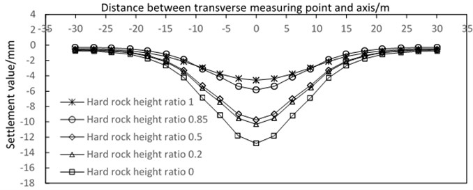
Fig. 12 shows the surface transverse settlement curve. The curve is a transverse surface settlement map of the monitoring section perpendicular to the vault of the shield tunnel. In shield tunneling, the transverse surface settlement law of the five monitoring sections shows that the corresponding surface settlement value of the tunnel vault is the largest, and the settlement value gradually decreases with the transverse monitoring point away from the vault of the tunnel. The settlement value near the monitoring point of the tunnel vault changes faster than that far from the monitoring point of tunnel vault. Generally, the measured lateral surface subsidence curve has evident settlement tank, which is consistent with the predicted curve of Peck.
Transverse surface subsidence is obviously affected by hard rock height ratio. The general trend is that the value of surface subsidence correspondingly decreases and settlement tank becomes shallow with the increase in hard rock height ratio. The surface subsidence in different hard rock height ratio strata is obviously different, and the maximum difference is about 8.6 mm; When the hard rock height ratio is 0.2 and 0.5, the curve of settlement tank does not change much. When the hard rock height ratio is 0.85 and 1, the curve also changes little. The maximum settlement difference of hard rock height ratio interval between 0.2-0.5 and 0.85-1 is only 1.4 mm. But in the hard rock height ratio interval between 0-0.2 and 0.5-1, the minimum difference of surface settlement is 3.2 mm. The settlement value reaches a maximum value of 13.2 when the hard rock height ratio is 0.
Fig. 12Transverse sinking curves of different hard rock height ratios
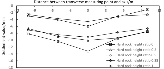
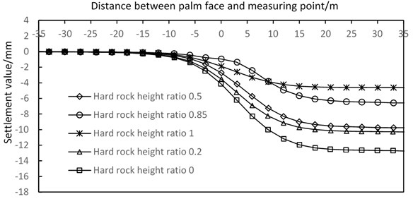
Fig. 13Longitudinal settlement curve of different hard rock height ratios
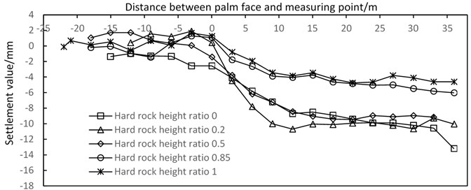
4.3.2. Analysis of monitoring results of longitudinal surface settlement
Fig. 13 shows the settlement curve, which is the surface longitudinal settlement under different hard rock height ratios during shield tunneling. From the figure, obvious uplift is observed at approximately 15-20 m ahead of the excavation face due to the influence of face pressure of palm, which belongs to negative stratum loss. At approximately 5 m ahead of the excavation face, surface deformation changes from uplift to subsidence with an accelerating trend. At the area of 5-10 m behind the excavation face, the surface subsidence rate is high, and the subsidence amount reaches approximately 83 % of the total subsidence. This subsidence which is influenced by the gap of shield structure belongs normal stratum loss. At approximately 20 m behind the excavation face, surface settlement is no longer affected by shield tunneling. Longitudinal surface subsidence is significantly affected by the hard rock height ratio, which shows that surface subsidence decreases with the increase in hard rock height ratio. The surface longitudinal settlement curves of tunnels with different hard rock height ratios are compared. The results show that with the increase of the hard rock height ratio, the location of surface deformation begins to decrease from approximately 15 m in front of the excavation face to approximately 10 m. Moreover, the surface subsidence rate has a decreasing trend with the increase in hard rock height ratio. Generally, with the increase of the hard rock height ratio, the influence degree and range of shield construction on the surface longitudinal settlement are decreasing.
5. Finite element numerical simulation analysis
5.1. Establishment of 3D numerical model
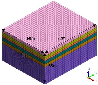
This study mainly investigates the law of surface subsidence caused by shield tunneling in the strata with different hard rock height ratios. In order to facilitate comparative analysis, five sections (YD170, YD203, YD200, YD161, and YD162) in Chapter 4 are selected for simulation. Five numerical models with hard rock height ratio of 0, 0.2, 0.5, 0.85 and 1 are established by MIDAS GTS. The models do not consider the effects of water and consolidation. The range of calculation model is 60 m in transverse direction ( direction), 72 m in longitudinal direction ( direction) and 38m in vertical direction ( direction). The overlaying soil of the tunnel is 14 m thick.
The model mesh is divided into tetrahedron + hexahedron mesh, which is a special hybrid mesh of MIDAS GTS. The grid can not only improve the calculation accuracy, but also improve the calculation speed. The grid in the excavation range of the tunnel needs to be divided into smaller ones, and the size is set to 0.5 m. The mesh is roughly divided at the boundary of the model, and the size is set to 3 m. Then, the dimension from the model boundary to the excavation decreases gradually according to the linear gradient. A finite element model with a hard rock height ratio of 0.5 is shown in Fig. 14.
Fig. 14Finite element model
After the 3D model is established, the boundary conditions of the model are set. The displacement boundary is selected as the boundary condition of the model. The upper interface of the model in the direction is free without any constraint. The element nodes of the lower interface and the surrounding boundary are set as fixed constraints, that is, the displacement in the , and directions is limited.
5.2. Setting of main parameters of the model
The Shield machine used in tunnel excavation is simulated by plate element, the material is made of steel, the elastic modulus is 250 GPa, the Poisson’s ratio is 0.2, and the bulk density is 78 kN/m3. The C50 concrete used in shield tunnel segment material is based on the Code for Design of Concrete Structure, which indicates that the elastic modulus of a segment should be 34.5 GPa. In view of the effects of annular and longitudinal splicing of segment on the reduction of segment stiffness, the elastic modulus of the segment in the model calculation is 80 % of the reduction value recommended by the code, that is, 27.6 GPa. The Poisson ratio of the segment is 0.2, and the plate element is used to simulate it. The segment grouting layer is equivalent to the mud water equivalent layer, the equivalent layer thickness is 0.3 m, and the solid element is used for simulation, and the hardening process of the slurry is not considered in the calculation process [39]. All of the above materials only consider the stress and deformation within the elastic range, that is, the elastic constitutive model is adopted. The physical and mechanical parameters of various materials of the model are shown in Table 1.
Table 1Geotechnical physical and mechanical parameters
Name | Severe (kN/m3) | Deformation modulus (MPa) | Cohesive force (kPa) | Internal friction angle (°) | Poisson’s ratio () |
Miscellaneous fill | 16.5 | 2.5 | 8 | 10 | 0.35 |
Mucky soil | 17 | 5 | 12.6 | 12.8 | 0.3 |
Find sand | 20.3 | 12 | 15 | 35 | 0.3 |
Medium coarse sand | 19.6 | 40 | 10 | 30.5 | 0.3 |
Gravel sand | 20.8 | 50 | 10 | 30.5 | 0.3 |
Slightly weathered limestone | 24.5 | 10000 | 1500 | 55 | 0.3 |
Shield machine | 78 | 250000 | – | – | 0.2 |
Segment | 25 | 27600 | – | – | 0.2 |
In order to more accurately reflect the situation of shield excavation, the model sets the pressure of tunnel face, cylinder thrust force and grouting pressure. The pressure of tunnel face is 120 kPa according to experience. The cylinder thrust force and grouting pressure shall be determined according to the actual situation, in which the cylinder thrust force is taken as 100 kN/m and the grouting pressure is taken as 150 kPa.
5.3. Numerical calculation method
The numerical model in this paper adopts the Mohr Coulomb failure criterion. Mohr proposed the strength formula in 1900: . According to Mohr’s theory, the yield of rock and soil is expressed as follows:
where – cohesion of soil; – internal friction angle of soil
The Eq. (4) shows that the shear strength of the material is related to the normal stress acting on the plane. It is not the maximum shear stress that causes material failure, but the most dangerous combination of - in a plane. In numerical analysis, Eq. (4) can be expressed by stress invariants as follows:
where – equivalent compressive stress; – Mises stress; – lode angle.
In the principal stress space, it appears as an irregular hexahedral vertebral body surface. The section shape on the plane is an irregular hexagon. As shown in Fig. 15(a), the hexagon needs to be determined by the length of and . These two quantities can be expressed as follows:
Since the geometric similarity of each plane of the Mohr Coulomb yield surface, the ratio of any plane is constant. As shown in Fig. 15(b), the slope of the straight line does not change with the confining pressure (or hydrostatic pressure), so the criterion is accurate when the confining pressure is in a certain range. The confining pressure of this project will not be large enough to produce compressive failure, so the mohr-coulomb failure criterion can be used to obtain very accurate results.
Fig. 15Shape of Mohr Coulomb yield surface
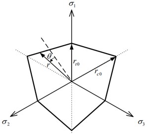
a) Yield surface shape of plane
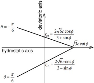
b) Yield surface shape of meridian plane
5.4. Shield excavation simulation
In order to improve the calculation efficiency and get close to the actual construction condition as much as possible, shield driving two ring segments (3 m) as a working condition, a total of 48 rings need to be driven after the completion of construction. Shield Excavation Simulation: (1) In the first step, the initial stress field is analyzed by applying dead weight and soil boundary conditions. The initial displacement is then reset to facilitate the study of the incremental displacement caused by tunnel excavation; (2) The second step is to “passivation” the soil mass of tunnel excavation, applies the pressure of tunnel face to stabilize the excavation face, “activates” the shield shell, simulates the shield tunneling process; (3) The third step “activates” the segment unit to simulate the assembly process of the shield tail segment; (4) The fourth step is to simulate shield tail synchronous grouting. “Activate” the slurry equivalent layer unit. The radial grouting pressure is applied on the grouting layer to consider the influence of grouting pressure on the stratum and segment. At the same time, “activate” cylinder thrust force to provide forward jacking force for the next excavation; (5) Repeat Steps (1)-(4) and continue digging until all segments are assembled.
5.5. Analysis of calculation results
Five stratum models with different hard rock height ratios are established to simulate the influence of shield excavation on surface subsidence under different hard layer conditions, such as transverse and longitudinal surface subsidence. To fully reflect the influence of shield excavation on ground surface settlement, cross sections of 10, 20, and 30 m are selected along the longitudinal stratum for analysis. The cross sections vertical and parallel to the tunnel vault are used for the analysis. Certain calculation models of stratum deformation nephogram are provided. Taking the model of hard rock height ratio of 0.5 as an example, Fig. 16 shows the cross-section deformation nephogram of 10 m after shield tunnel penetration, and Fig. 17 shows the longitudinal deformation nephogram after shield tunnel penetration.
Fig. 16Nephogram of cross-section settlement calculation after tunnel penetration (β= 0.5)
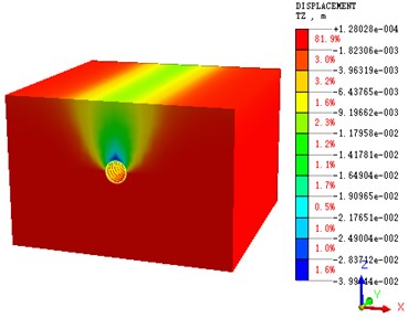
Fig. 17Nephogram of longitudinal section settlement calculation after tunnel penetration (β= 0.5)
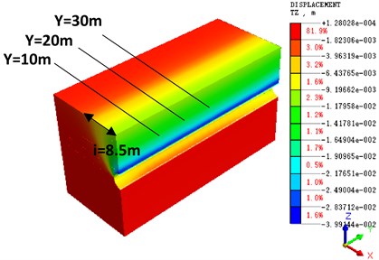
It can be seen from the settlement nephogram that when the hard rock height ratio is 0.5, the surrounding rock in the lower half of the tunnel excavation face is basically in a stable state, and the impact of the disturbance is very small. There is a certain uplift phenomenon at the bottom of tunnel arch, which is mainly due to the unloading effect caused by tunnel excavation. There is a large settlement at the vault, and the maximum settlement is nearly 40 mm. Due to half of the soft stratum in the tunnel excavation face, it is necessary to strictly control the excavation parameters and adjust the excavation attitude, so as to effectively control the uneven settlement caused by the disturbance of the soft stratum. It can be seen from the calculation nephogram that there is obvious settlement trough phenomenon in the stratum settlement, and the surface settlement conforms to the Peck curve. As the buried depth of the tunnel is 16.7 m, and the internal friction angle is 10°-55°, the theoretical value 7.94 m-21.13 m can be obtained by substituting the Eq. (1). The computational nephogram shows 8.5 m, which is in the theoretical range. Through the prediction of the value of the inflection point i and the range of the settlement groove, the range of the influence of shield construction on the stratum can be determined, and effective control measures can be taken in time to reduce the influence.
The transverse settlement curves corresponding to the hard strata height ratio with different proportions are plotted with 10, 20, and 30 m.
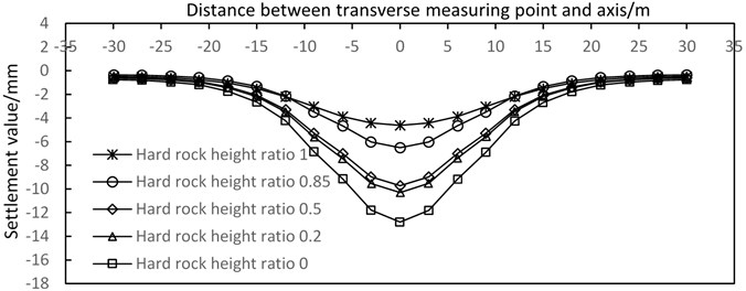
For different hard rock height ratio strata, the lateral surface subsidence is immensely affected by the hard rock height ratio, and the surface influence range is between 3D and 3.5D when the values are 0, 0.5, and 1, with corresponding maximum settlement values of 12.8 9.7, and 4.6 mm, respectively (Fig. 18).
As shown in Fig. 18, after the completion of tunnel excavation, the curve of settlement trough is consistent with Peck’s prediction, and the law of transverse surface settlement of each monitoring section is basically the same. The sequence of shield excavation has small influence on the law of transverse surface settlement. The depth of settlement tank increases and its width decreases with the increase in hard rock height ratio. The settlement tank is basically shallow and wide when the hard rock height ratio is 1. The settlement tank gradually exhibits the characteristics of “deep and narrow” with the decrease of .
Fig. 19 shows the simulation curve of the longitudinal surface settlement varying with hard rock height ratio. From the figure, the longitudinal settlement value of the tunnel decreases with the increase in hard rock height ratio. When the hard rock height ratio varies from 0 to 0.2, shield tunneling can affect the ground subsidence at approximately 15 m ahead of the excavation face and ground subsidence tends to be stable at approximately 20 m after excavation face. When the ground subsidence tends to be stable, the settlement value reaches 98 % of the total settlement. Shield tunneling only affects the ground subsidence at approximately 10 m before excavation face when the hard rock height ratio varies from 0.5 to 1 and ground subsidence tends to be stable at approximately 20 m after excavation face. Surface subsidence reaches 96 % of the total settlement at approximately 14 m after the excavation surface when the hard rock height ratio is 1. With the increase of the hard rock height ratio, the shield construction reduces the amount of the surface longitudinal settlement and its influence range. Generally, the simulated values fit well with the measured values. However, the simulation of longitudinal surface settlement does not show the phenomenon of surface uplift in front of the excavation face, which may be related to the methods of numerical simulation and the selection of pressure of tunnel face.
Fig. 18Settlement curves of different hard rock height ratios in the cross section after tunnel excavation

a) 10
b) 20
c) 30
Fig. 19Simulated curves of vertical surface subsidence with different hard rock height ratios
5.6. Comparative analysis of numerical results and monitoring results
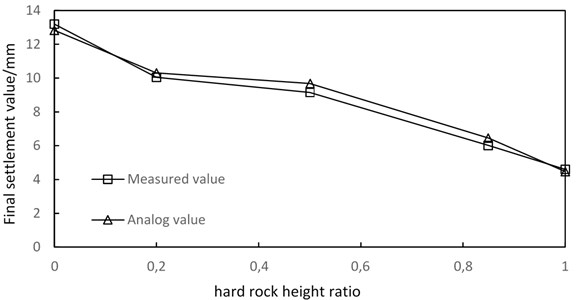
In order to verify the reliability of the numerical model, the monitoring results are compared with the numerical calculation results. As shown in Fig. 20, the relation curve between the maximum surface subsidence above the vault and the hard rock height ratio is shown. The variation of the simulated value and the measured value with the hard rock height ratio is shown in the figure. It can be seen from the figure that the numerical simulation results and the measured results fit well, and the results of both show the same trend of change. The maximum surface subsidence decreases with the increase of the hard rock height ratio. When the hard rock height ratio is in the range of 0.2-0.5, the influence of the hard rock height ratio on the maximum surface settlement value is not significant. When the hard rock height ratio is in the range of 0-0.2 and 0.5-1, the change rate of the maximum subsidence value is greatly affected by the hard rock height ratio. The rate of change between 0-0.2 is the largest. Therefore, special attention should be paid to these two sections in order to prevent uneven ground settlement during the construction of sensitive sections.
From the monitoring results, the numerical calculation results can well predict the settlement trend under different hard rock height ratio, and the monitoring results verify the accuracy of the numerical calculation model.
Fig. 20Contrast curve of measured and simulated ground settlements above the tunnel vault
6. Conclusions
In this paper, numerical simulation and site monitoring are used to study the influence of shield tunneling on the ground settlement in the upper soft and lower hard strata by introducing the concept of hard rock height ratio. The following conclusions are obtained:
1) The surface subsidence is obviously affected by the hard rock height ratio. With the increase of the height ratio of hard rock, the surface settlement value decreases, and the settlement trough changes from “deep narrow” to “shallow wide”. The surface subsidence in different hard rock height ratio strata is obviously different, and the maximum difference is about 8.6 mm. When the height ratio of hard rock is 0, the surface subsidence reaches the maximum value, the maximum value is 13.2 mm.
2) The influence of the hard rock height ratio on the surface longitudinal settlement is mainly reflected in the position change of the beginning and the end of the settlement. With the increase of the hard rock height ratio, the location of surface deformation begins to decrease from approximately 15 m in front of the excavation face to approximately 10 m. The settlement of different hard rock ratio tends to be stable at approximately 20 m after excavation face.
3) The monitoring results verify the accuracy of the numerical results. The hard rock height ratio in the 0-0.2 and 0.5-1 is the sensitive interval, and the settlement value in these two hard rock height ratio interval varie greatly. The maximum settlement difference of hard rock height ratio interval in 0.2-0.5 is only 1.4 mm, but in the hard rock height ratio interval between 0-0.2 and 0.5-1, the minimum difference of surface settlement is 3.2 mm. It is necessary to pay attention to the uneven settlement of the ground surface caused by shield construction in the sensitive hard rock height ratio interval.
References
-
Lv J. B., Li X. L, Li Z. R., Fu H. L. Numerical simulations of construction of shield tunnel with small clearance to adjacent tunnel without and with isolation pile reinforcement. KSCE Journal of Civil Engineering, Vol. 24, 2020, p. 295-309.
-
Li Y., Qi T. Y., Lei B., Qian W. P., Li Z. Y. Deformation patterns and surface settlement trough in stratified jointed rock in tunnel excavation. KSCE Journal of Civil Engineering, Vol. 23, Issue 7, 2019, p. 3188-3199.
-
Lai H. P., Zhang J., Zhang L. Y., Chen R., Yang W. J. A new method based on centrifuge model test for evaluating ground settlement induced by tunneling. KSCE Journal of Civil Engineering, Vol. 23, Issue 6, 2019, p. 2426-2436.
-
Yuan B. X., Sun M., Wang Y. X., Zhai L. H., Luo Q. Z. Full 3D displacement measuring system for 3D displacement field of soil around a laterally loaded pile in transparent soil. International Journal of Geomechanics, Vol. 19, Issue 5, 2019, https://doi.org/10.1061/(ASCE)GM.1943-5622.0001409.
-
Zhang Z. G., Shi M. Z., Zhang C. P., Wei G., Wang Z. W., Zhao Q. H. Study on deformation of adjacent underground pipelines caused by rectangular shield tunnel excavation. Journal of Rock Mechanics and Engineering, Vol. 38, Issue 4, 2019, p. 852-864.
-
Wei G., Pang S. Y. Study on three-dimensional soil deformation caused by construction of double-line parallel shield tunnel. Geotechnical Mechanics, Vol. 35, Issue 9, 2014, p. 2562-2568.
-
Yuan B. X., Xiong L., Zhai L. H., Zhou Y. F., Chen G. F., Gong X., Zhang W. Transparent synthetic soil and its application in modeling of soil-structure interaction using optical system. Frontiers in Earth Science, Vol. 7, 2019, p. 276.
-
Liang R. Z., Xia T. D., Lin C. G., Yu F. Analysis of surface deformation and horizontal displacement of deep soil caused by shield driving. Journal of Rock Mechanics and Engineering, Vol. 34, Issue 3, 2015, p. 583-593.
-
Wang Y. X., Guo P. P., Li X., Lin H. Behavior of fiber-reinforced and lime-stabilized clayey soil in triaxial tests. Applied Sciences-Basel, Vol. 9, Issue 5, 2019, p. 90.
-
Liu H., Yang H. L. Construction Technology of Earth Pressure Balanced Shield Tunnel in Shallow High-Viscous Upper-Soft-Lower Hard and Bad Strata of Changsha-Zhuzhou-Tan Intercity Railway. Tunnel Construction, Vol. 36, Issue 2, 2016, p. 221-227.
-
Peck R. B. Deep excavations and tunneling in soft ground. Proceedings of 7th International Conference on Soil Mechanics and Foundation Engineering, 1969.
-
Chen C. L., Zhao Wei C. L. G., Ding Z. Prediction of soil settlement caused by double-line shield based on Peck formula. Geotechnical Mechanics, Vol. 35, Issue 8, 2014, p. 2212-2218.
-
Zhu C. H. Control of surface settlement by considering shield tunneling technology. KSCE Journal of Civil Engineering, Vol. 21, Issue 7, 2012, p. 2896-2970.
-
Hu D. H., Duan J. C. Study on stratum deformation law of double-track metro tunnel under existing urban roads in upper soft and lower hard strata. Journal of Disaster Prevention and Mitigation Engineering, Vol. 37, Issue 6, 2017, p. 910-915.
-
Yuan B. X., Sun M., Xiong L., Luo Q. Z., Sarada P. P., Li H. Z. Investigation of 3D deformation of transparent soil around a laterally loaded pile based on a hydraulic gradient model test. Journal of Building Engineering, Vol. 28, Issue 3, 2020, p. 101024.
-
Sun K. G., Xu W. P., Qiu W. G., Li H. B., Xian Q. Y., Li T. Study on the characteristics of safety distribution changing with buried depth for metro station in upper-soft and lower-hard stratum. Advances in Civil Engineering, Vol. 2018, 2018, p. 6047919.
-
Liu J. H. An overview of shield construction technology expert system for Shanghai soft soil tunnel. Underground Works and Tunnels, Vol. 2, 1995, p. 2-8.
-
Zhang Z. G., Zhang C. P., Jiang K. M., Wang Z. W., Jiang Y. J., Zhao Q. H., Lu M. H. Analytical prediction for tunnel-soil-pile interaction mechanics based on Kerr foundation model. KSCE Journal of Civil Engineering, Vol. 23, Issue 6, 2019, p. 2756-2771.
-
Fang Y., He C., Nazem A., Yao Z. G., Grasmick J. Surface settlement prediction for EPB shield tunneling in sandy ground. KSCE Journal of Civil Engineering, Vol. 21, Issue 7, 2017, p. 2908-2918.
-
Yang Y., Fu H. J., Zhang D. R., Huo H. Y. The influence of shield construction parameters on ground settlement and control measures. Urban Rail Transit Research, Vol. 21, Issue 12, 2018, p. 61-66.
-
Wang Y. X., Guo P. P., Lin H., Li X., Zhao Y. L., Yuan B. X., Liu Y., Cao P. Numerical analysis of fiber-reinforced soils based on the equivalent additional stress concept. International Journal of Geomechanics, Vol. 19, Issue 11, 2019, https://doi.org/10.1061/(ASCE)GM.1943-5622.0001504.
-
Luo Y. B., Chen J. X., Wang H. Y., Sun P. L. Deformation rule and mechanical characteristics of temporary support in soil tunnel constructed by sequential excavation method. KSCE Journal of Civil Engineering, Vol. 21, Issue 6, 2017, p. 2439-2449.
-
Zhang A. J. Study on fuzzy control of shield tunneling attitude construction parameters in upper soft and lower hard grounds. Journal of Railway Science and Engineering, Vol. 15, Issue 11, 2018, p. 2920-2927.
-
Zhang Y. G., Yao Z. H. Research and application of tool configuration and Optimization for super large diameter shield tunneling across upper soft and lower hard strata of the Yangtze River. Modern Tunnel Technology, Vol. 55, Issue 2, 2018, p. 180-188.
-
Ye F., Mao J. H., Liu Y. P., Jia T., Wang C. B. Model test of dynamic pressure arch effect on surrounding rock of weak and fractured tunnel. China Journal of Highway, Vol. 28, Issue 10, 2015, p. 76-82.
-
Akl S. A., Metwally K. G. Optimizing arching creation for Abou Muharik Tunnel in Egypt using numerical analysis. KSCE Journal of Civil Engineering, Vol. 21, Issue 1, 2015, p. 160-167.
-
Wang Z. X., Shi Z. Particle flow simulation of soil subsidence caused by tunnel construction in sandy soil. Tunnel Construction, Vol. 36, Issue 2, 2016, p. 158-163.
-
Sun X. H., Miao L. C., Lin H. S. Study on soil arching effect before excavation of shield tunnels with different buried depth in sandy soil. Geotechnical Mechanics, Vol. 38, Issue 10, 2017, p. 2980-2988.
-
Oh J. Y., Ziegler M. Investigation on influence of tail void grouting on the surface settlements during shield tunneling using a stress-pore pressure coupled analysis. KSCE Journal of Civil Engineering, Vol. 18, Issue 3, 2014, p. 803-811.
-
Yuan B. X., Chen R., Deng G., Peng T., Luo Q. Z., Yang X. Q. Accuracy of interpretation methods for deriving p-y curves from model pile tests in layered soils. ASTM Journal of Testing and Evaluation, Vol. 45, Issue 4, 2017, p. 1238-1246.
-
Lv J. B., Li X., He Y. W., Fu H. L., Yin Y. M. Analytical analyses of the effect of filled karst cavern on tunnel lining structure under complex geological conditions. AIP Advances, Vol. 9, Issue 3, 2019, p. 35148.
-
Shi C. H., Cao C. Y., Lei M. F. An analysis of the ground deformation caused by shield tunnel construction combining an elastic half-space model and stochastic medium theory. KSCE Journal of Civil Engineering, Vol. 21, Issue 5, 2017, p. 1933-1944.
-
Zhang J., Li D., Yu L. Upper-bound finite element adaptive analysis of plane strain heading in soil with a soft upper layer and hard lower layer. Advances in Civil Engineering, Vol. 2019, 2019, p. 7387635.
-
Deng B., Gu X. F. Shield tunneling construction technology research in upper soft and lower hard ground. Modern Tunneling Technology, Vol. 49, Issue 2, 2012, p. 59-64.
-
Wang J., He C., Hu R. Q., Dai G. H., Wang S. M. Study on disturbance of upper soft and lower hard strata in EPB shield tunneling. Journal of Rock Mechanics and Engineering, Vol. 36, Issue 4, 2017, p. 953-963.
-
Wu K., Zhang W., Wu H. T., Wang Y. J., Yu Y. L. Deformation regularity and control measures of metro tunnels under existing urban roads in upper soft and lower hard strata. Modern Tunnel Technology, Vol. 54, Issue 6, 2017, p. 126-135.
-
Yang S. Q., Chen M., Fang G., Wang Y. C., Meng B., Li Y. H., Jing H. W. Physical experiment and numerical modelling of tunnel excavation in slanted upper-soft and lower-hard strata. Tunnelling and Underground Space Technology, Vol. 82, 2018, p. 248-264.
-
Wang J. B., Huo Q., Song Z. P., Zhang Y. W. Study on adaptability of primary support arch cover method for large-span embedded tunnels in the upper-soft lower-hard stratum. Advances in Mechanical Engineering, Vol. 11, Issue 1, 2019, https://doi.org/10.1177/1687814018825375.
-
Zhang Y., Yin Z. Z., Xu Y. F. Surface Deformation Analysis Caused by Shield Tunneling. Journal of Rock Mechanics and Engineering, Vol. 21, Issue 3, 2002, p. 388-392.
About this article

Firstly, this study has been supported by National Natural Science Foundation of China Project (Nos: 51508109 and 51608085), and the Natural Science Foundation of Guangdon Province under Grant Number 2016A030310346. Secondly, the authors acknowledge the financial support provided by the Guangdong Provincial Natural Science Foundation of China (Grant No. 2019A1515011397), Chinese National Natural Science Foundation (Grant No. 51978668) and Chinese National Natural Science Foundation (Grant No. 51978177). At last, the authors would like to thank China Tunnel Construction Group Co. Ltd., Guang Dong for their assistance and support.
