Abstract
Highway tunnels built in China in the early years of operation have different forms of diseases, which have a great impact and threat to the normal operation and safety of the tunnel. To ensure the safety and stability of the lining structure, this paper analyzes the mechanical behavior of the lining structure under the influence of the disease and reveals the evolution law of the lining crack disease for typical tunnel lining cracks. The results of the study show that only the circumferential and longitudinal stresses at the vault increase when cracks exist in the inner wall of the lining vault. The longitudinal cracks in the inner wall of the lining have the greatest influence on the lining stress state.
Highlights
- Conducted indoor model tests
- Analyzed the mechanical behavior of lining structure under the influence of disease
- Revealed the evolution of lining crack disease under the action of typical tunnel lining cracks
1. Introduction
In the rapidly developing construction projects of highways, high-speed railroads, and subways, tunnel structures occupy an irreplaceable position with their outstanding advantages. The geological environment of the tunnel is often complex and changeable, and many tunnels have disease types of lining cracks due to factors such as low design level, poor construction quality, changes in the stressful environment, and insufficient operation protection. Tunnel lining cracks, as a common lining disease in operating tunnels, are also one of the causal factors for other lining diseases. Further development of lining cracks will likely lead to a series of diseases such as lining cracking, deformation, spalling, and water seepage.
To better enhance the protection of tunnel lining and study the mechanical behavior of lining structure due to the existence of lining cracks, many scholars have carried out relevant research. Xu et al. [1] conducted a field survey to reveal the cracking of these highway tunnels and finally analyzed the cracking characteristics of intact and cracked linings using similarity model tests. Xu [2] used radar scanning, drilling and coring, and laser scanning to elucidate the tunnel’s disease characteristics and failure causes, and also innovatively proposed a set of solutions for cracks, water seepage, inversions, and other diseases. Yuan [3] used a combination of model tests and numerical simulations to focus on the effect of tunnel lining cracking on the structural force performance. Zhao [4] simulated the crack damage using field monitoring and combined it with finite element numerical simulation analysis, using lining thickness discounting, and derived the tunnel lining dangerous crack depth by comparing the minimum safety factor specified in the specification. Xiong [5] studied the effect of blasting pressure on the stability of the subway tunnel lining structure during the excavation of the connection channel and proposed a safe blasting construction distance. Liu et al. [6] proposed a beam-spring model for calculating the stiffness of lining cracks through the vault model of a 1:1 tunnel lining structure and studied the influence of crack location, depth, and ground stress on the bearing capacity of the lining structure. Xu et al. [7] studied the lining cracks of the Fuzhou Metro Line 1 tunnel crossing the composite ground. The mechanical response of lining under the influence of non-interpenetrated longitudinal cracks was studied by indoor model test, and a new numerical method of the crack segment was proposed to analyze the mechanical behavior of multi-crack lining.
Further, many scholars have carried out related research through laboratory tests and numerical simulations. Yu [8] studied the distribution of structural forces in the case of lining cracks at different locations in the tunnel and explored the effect of cracks on the safety of the lining structure. Liu [9] used model tests and numerical simulations to analyze and evaluate the tunnel lining cracks. Song [10] conducted similar tests based on his field test results, analyzed in detail the deformation pattern and damage characteristics of the tunnel structure during the test, and evaluated the working condition of the tunnel prototype based on the test results. Huang et al. [11] analyzed the development law of lining cracks in tunnel lining structure under the influence of different factors such as bias, the cavity behind lining, uneven settlement, relaxation pressure, and landslide by extended finite element numerical calculation method. Zhang et al. [12] used the hybrid finite element-discrete element method and model test to study the initial cracking, expansion, and crushing process of structural cracks in shallow tunnel lining underground stress. Song et al. [13] made statistics on the lining cracks of a tunnel in a loess area through field investigation, and studied the expansion of lining cracks through the 1:10 model test. Liu et al. [14] verified the reliability of the extended finite element numerical calculation method in the study of simulated lining cracking through full-scale tests, and simulated the generation and expansion of cracks in bias tunnels underground stress by numerical calculation.
Scholars have researched the mechanical behavior of lining under the influence of lining cracks and the evolution law of the disease through numerical simulation and indoor model tests, and have achieved certain results, but the following deficiencies still exist in the research. The simulation of lining structure in the indoor model test study of highway tunnels often only considers the plain concrete structure, which fails to truly reflect the real working conditions. The numerical modeling process of road tunnel lining structure often does not take into account the combined mechanical properties of steel and concrete.
2. Statistical analysis of tunnel engineering and lining diseases
Wushan Tunnel is located in Wushan County, Tianshui City. The length of the upstream line of the Wushan tunnel (referred to as the Wushan tunnel) is 2495 m, and the maximum buried depth is 269.079 m, which belongs to the deep buried long tunnel of a rock mountain. The tunnel site is located in the low-middle mountain area of tectonic denudation sedimentary rock. The ground elevation is 1481.16 m-1761.38 m, and the maximum relative height difference is 280.22 m. The slope of entrance slope of the tunnel is about 33°-42°, which is the third terrace of the Weihe River.
The engineering geological conditions of the tunnel are complex, mainly passing through grade V and IV surrounding rock. Through the analysis of the geological radar detection results of the lining diseases of Wushan Tunnel, the lining diseases existing on site are: insufficient lining thickness, the cavity behind lining, uncompacted lining, lining spalling, lining cracks, and lining seepage. Among the lining diseases in the Wushan tunnel, the number of lining cracks is the most, 1102 in total. There are 57 voids behind the lining. The lining is not dense a total of 23, lining peeling a total of 3, lining seepage a total of 3, lining thickness less than a total of 1.
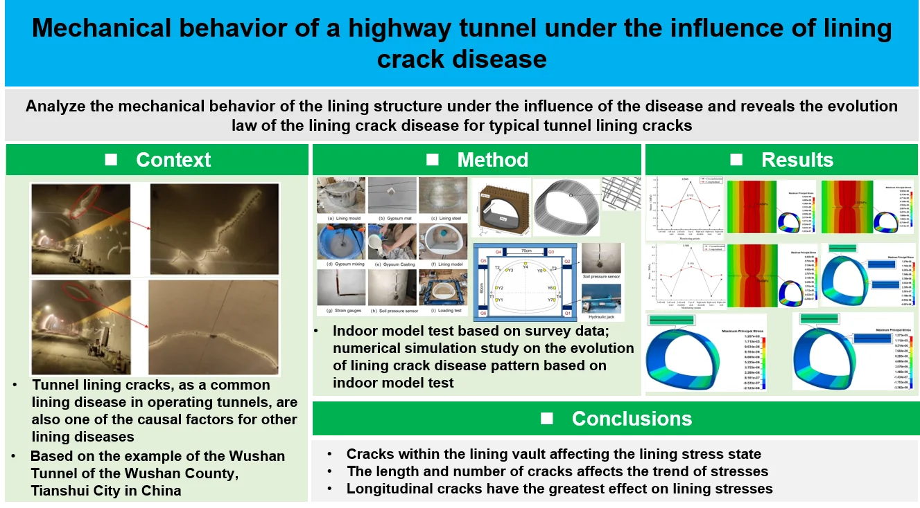
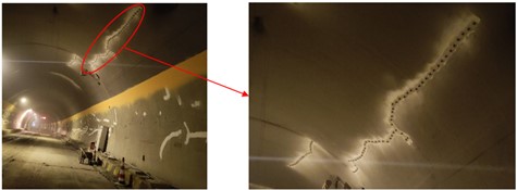
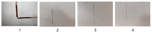
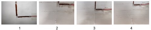
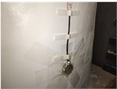
As one of the main lining diseases of Wushan tunnel, circumferential cracks, diagonal cracks, and longitudinal cracks are mainly distributed in the vault, and few in the spandrel, hance, and side wall, as shown in Fig. 1. The types of lining cracks in Wushan tunnel are mainly longitudinal and circumferential, 583 and 452 respectively, and the number of oblique cracks in the least, only 67. The length of cracks is mostly concentrated in the range of 1 m-5 m. The length and width characteristics of different types of lining cracks are shown in Table 1. The distribution range of crack length is large, ranging from 0.11 m to 15.05 m, and the maximum crack width is 7 mm.
Through on-site geological conditions and lining crack detection, it is analyzed that there are two main reasons for a large number of longitudinal and circumferential cracks and a small number of oblique cracks in the Wushan tunnel lining.
Geological conditions: The surrounding rock is mainly mudstone. Under the action of ground stress, a certain degree of deterioration occurs. The loose circle of surrounding rock behind the lining expands, which leads to the increase of loose load. Longitudinal cracks are easy to occur in the weak position of the lining, especially in the arch area. In the process of tunnel operation, the surrounding rock of the basement is softened and broken due to the action of vehicle and groundwater, and the lining structure is unevenly settled horizontally and vertically, which leads to the circumferential, longitudinal, and oblique cracking of the lining structure.
Construction quality: During the construction process, the inverted arch pouring is completed, and the side wall joint surface is not under the requirements of the specification for chiseling treatment, steel lap does not meet the requirements, resulting in a certain degree of deformation and displacement at the side wall, resulting in side wall lining longitudinal cracking. Under-excavation occurred during the excavation of the tunnel, but the under-excavation part was not treated before the lining was poured, which led to the failure of the lining thickness to meet the design requirements after the completion of the secondary lining pouring of this part, the bending and tensile capacity of the lining decreased, and the lining structure cracks occurred under the action of ground stress. Hydration heat is produced in the process of lining pouring, and temperature cracks occur. The secondary lining is removed too early and not maintained according to the standard, resulting in insufficient lining strength and circumferential and oblique cracks under the action of ground stress.
Fig. 1Arch crack of Wushan tunnel
a) Longitudinal cracks in the vault of the Wushan tunnel
b) Circumferential cracks in the vault of the Wushan tunnel
Table 1Length and width characteristics of lining cracks
Types of lining cracks | Circumferential crack | Inclined crack | Longitudinal crack |
Length (m) | 0.31-10.85 | 0.11-7.37 | 0.45-15.05 |
Width (mm) | 0.3-6 | 0.3-5 | 0.2-7 |
3. Model test study on the mechanical behavior of diseased lining of highway tunnel during operation
3.1. Model test condition design
The simulation of lining cracks in this model test is based on the disease condition of the Wushan Tunnel. Wushan tunnel lining cracks are mainly concentrated in the arch, and the indoor model experiments mainly study the circumferential and longitudinal cracks in the arch, and the length and number of cracks are taken as the main research variables.
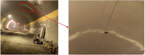
The simulations of lining cracks are mainly: circular cracks of different lengths, longitudinal cracks of different lengths, and circular cracks of different numbers, and the working conditions are designed as in Table 2. For different lengths of circumferential cracks simulation: cracks are set along the circumferential direction of the vault, keeping the crack width × depth = 0.5 mm × 2 cm unchanged, and only the crack length is changed, the crack setting in the indoor model test is shown in Fig. 2(a). For a different number of circumferential cracks simulation, the working conditions are no cracks, 1, 2 and 3 cracks of 15 cm × 0.5 mm × 2 cm in the circumferential direction of the vault, and the crack settings in the indoor model test are shown in Fig. 2(c).
Table 2Lining crack test working conditions
Work conditions | Circumferential cracks of different lengths (cm) | Longitudinal cracks of different lengths (cm) | Circumferential cracks with different numbers |
1 | 0 | 0 | 0 |
2 | 5 | 5 | 1 |
3 | 10 | 10 | 2 |
4 | 15 | 15 | 3 |
Fig. 2Cracks in different working conditions
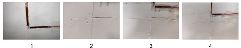
a) Circumferential cracking conditions of different lengths
b) Longitudinal cracks of different lengths
c) Circumferential cracking condition with different numbers of cracks
3.2. Simulation of tunnel ground stress during operation
In this test, only the simulation of tunnel ground stress conditions in the deeply buried case is considered. According to the Highway Tunnel Design Specification (JTG 3370.1-2018) [15], the vertical mean pressure and horizontal mean pressure of loose loads in deeply buried tunnels, under the surrounding rock conditions without significant bias and expansion forces, can be obtained from the geological conditions of Wushan Tunnel and the background of the study of the five-level surrounding rock section, the deep buried vertical distributed pressure is 0.265 MPa and the deep buried horizontal distributed pressure is 0.133 MPa.
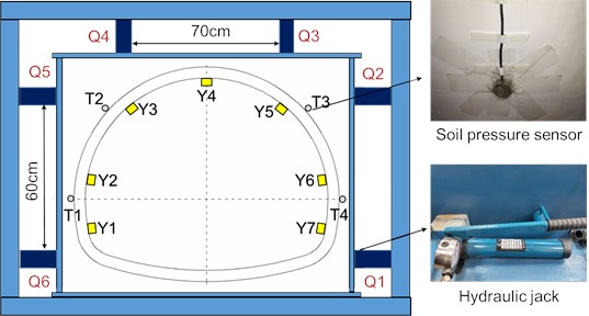
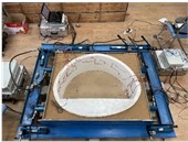
Model test using hydraulic jacks for loading, jack specifications for 10T can be horizontal hydraulic jacks. A total of 6 units, jacks Q3 and Q4 are located at the top of the tunnel lining model to simulate the vertical uniform pressure on the lining structure, Q5 and Q6 on the left side of the tunnel lining, and Q1 and Q2 on the right side, to simulate the horizontal uniform pressure on the tunnel lining structure. Using a 1cm thick steel plate at the front end and a powdered clay medium between the steel plate and the lining structure, the jack can convert the point load into a uniform load applied on the tunnel lining structure. Soil pressure sensors T1, T2, T3, and T4 are fixed at the left arch waist, left arch shoulder, right arch shoulder, and right arch waist on the surface of the lining structure respectively, which are connected to the DH5956 dynamic signal test and analysis system, and the accurate loading of the tunnel lining structure can be realized through the readings of the soil pressure sensors. The lower part of the jack is in contact with the reaction frame, and the model is loaded by the reaction force provided by the frame, and the loading system is shown in Fig. 3.
Fig. 3Loading system
3.3. Model test monitoring systems
The test mainly monitored the stress changes of the tunnel lining under the action of ground stress, and the 120-50A type resistance strain gauges were used for measurement. The strain gauges Y1-Y7 were attached to the left wall, left arch waist, left arch shoulder, vault top, right arch shoulder, right arch waist, and a right wall on the inner side of the lining structure, as shown in Fig. 4. The data of the strain gauges were collected by the DH3817F dynamic and static stress-strain test and analysis system, as shown in Fig. 5.
Fig. 4Strain gauge arrangement
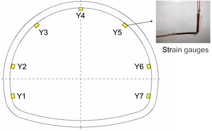
Fig. 5DH3817F test and analysis system
3.4. Model experiment implementation process
According to the cross-sectional dimensions of the tunnel lining in the indoor model, the lining mold was made by bonding the 60 cm long, 1 mm thick iron sheet with an acrylic plate through epoxy resin; the gypsum slurry was fully mixed and poured; the mold was demolded after 3 days of maintenance at room temperature and continued to be maintained at room temperature for 14 days before the back-arch filling was poured; after the lining maintenance time reached the specification requirements, the lining was designed by the test working conditions. After the maintenance time of the lining reaches the requirements of the specification, the lining cavity and lining cracks are cut out manually at different locations; four 14# I-beams are welded to form a rectangular reaction frame; strain gauges are glued to the designated locations of the lining structure according to the test requirements; earth pressure sensors are fixed to the designated locations of the lining structure; powdered clay material is filled in between the lining structure and the loading steel plate and compacted in layers until the clay reaches the same height of the lining. After normal testing, the lining structure is slowly pressurized by hydraulic jacks; the pressure on the lining structure is determined by the reading of the soil pressure sensor, and when the pressure is reached, the pressurization is stopped and the reading of the strain gauges is recorded. The strain gauge readings were recorded. The main test procedure is shown in Fig. 6.
Fig. 6Main test process
a) Lining mould
b) Gypsum mat
c) Lining steel
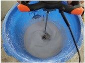
d) Gypsum mixing
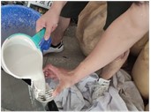
e) Gypsum casting
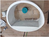
f) Lining model
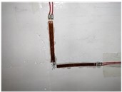
g) Strain gauges
h) Soil pressure sensor
i) Loading test
4. Analysis and discussion of model test results
4.1. Circumferential cracks of different lengths in the lining
The circumferential and longitudinal stresses at each monitoring point for different circumferential crack length test conditions at the inner wall of the lining vault in the statistical model test. As shown in Fig. 7(a), when there is a crack of 5 cm length in the inner wall of the lining vault, under the action of vertical and horizontal uniform load, the circumferential tensile stress and longitudinal tensile stress at the lining vault increase due to the presence of the crack, which is 0.545 MPa and 0.113 MPa, respectively, compared with the disease-free test condition, which increases 7.71 % and 11.88 %, respectively, and there is no significant change in the stress state at other locations. When the crack length of the inner wall of the lining vault increases to 10 cm, as in Fig. 7(b), the circumferential tensile stress and longitudinal tensile stress at the vault further increase to 0.580 MPa and 0.119 MPa, respectively, which increase by 14.62 % and 17.82 %, respectively, compared with the disease-free test condition, and there is no significant change in the stress state at other locations. With the increase of the circumferential crack length of the inner wall of the arch to 15 cm, as shown in Fig. 7(c), the circumferential tensile stress and longitudinal tensile stress at the top of the arch further increased to 0.638 MPa and 0.130 MPa, respectively, which increased by 26.09 % and 28.71 %, respectively, compared with the disease-free test condition, and there was no significant change in the stress state at other locations.
Fig. 7Circumferential cracks of different lengths in the lining
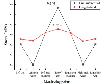
a) Crack in lining ring direction 5 cm×0.5 cm×2 cm
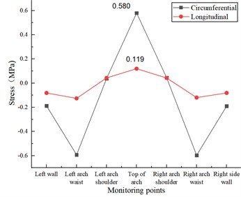
b) Crack in lining ring direction 10 cm×0.5 cm×2 cm
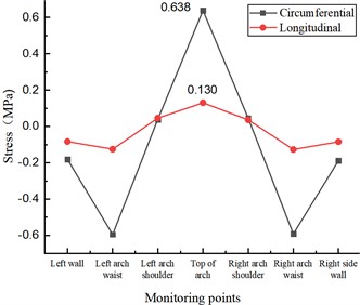
c) Cracks in lining ring direction 15 cm×0.5 cm×2 cm
4.2. Longitudinal cracks in different lengths of the lining
Under the action of vertical and longitudinal uniform load, the stress state of the lining structure will change due to the existence of longitudinal cracks in the inner wall of the vault, and the stress change is mainly manifested by the increasing circumferential tensile stress and longitudinal tensile stress at the vault, while the stress state at other locations is unchanged. As shown in Fig. 8(a), when the length of lining cracks in the inner wall of the vault is 5 cm, the circumferential tensile stress and longitudinal tensile stress at the vault are 0.569 MPa and 0.130 MPa respectively, which increase by 12.45 % and 28.71 % respectively compared with the disease-free condition. As in Fig. 8(b), when the length of lining cracks in the inner wall of the vault is 10 cm, the circumferential tensile stress and longitudinal tensile stress at the vault are 0.616 MPa and 0.133 MPa, respectively, which increase by 21.74 % and 31.68 %, respectively, compared with the disease-free condition. As in Fig. 8(c), when the length of the lining crack in the inner wall of the vault is 15 cm, the circumferential tensile stress and longitudinal tensile stress at the vault are 0.686 MPa and 0.149 MPa, respectively, which increase by 35.57 % and 47.52 % compared with the disease-free condition.
Fig. 8Longitudinal cracks in different lengths of lining
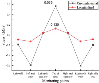
a) Lining longitudinal 5 cm×0.5 cm×2 cm cracks
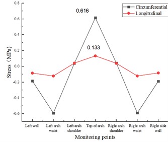
b) Lining longitudinal 10 cm×0.5 cm×2 cm cracks
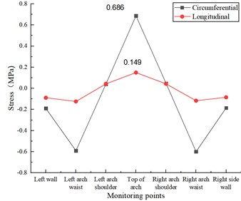
c) Lining longitudinal 15 cm×0.5 cm×2 cm cracks
4.3. Lining different numbers of annular cracks
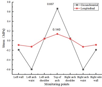
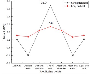
Fig. 9 shows the stress data of a different numbers of annular cracks in the lining. Combined with Fig. 7, it can be seen that as the number of circumferential cracks in the inner wall of the vault increases, the stress state of the lining structure under the action of ground stress changes relative to the undamaged case, and the change in stress is mainly reflected in the increasing circumferential tensile stress and longitudinal tensile stress in the vault, while in other locations of the lining, the stress does not change.
Fig. 9Circumferential cracks in the lining with different numbers of strips
a) 2 cracks in the lining ring
b) 3 cracks in the lining ring
As in Fig. 9(a), when the lining damage is 2 cracks of 15 cm×0.5 cm×2 cm at the top of the arch, the annular tensile stress and longitudinal tensile stress at the top of the arch are 0.667 MPa and 0.140 MPa respectively, which increase 31.82 % and 38.61 % respectively compared with the disease-free test condition. As shown in Fig. 9(b), when the lining damage is three cracks of 15 cm×0.5 cm×2 cm at the top of the arch, the circumferential tensile stress and longitudinal tensile stress at the top of the arch are 0.691 MPa and 0.146 MPa respectively, which are increased by 36.56 % and 44.55 % respectively compared with the disease-free test condition.
5. Numerical simulation study on the evolution of highway tunnel lining crack disease law
5.1. Numerical modeling approach considering the combined structure of liner concrete and internal reinforcement
5.1.1. Numerical calculation model
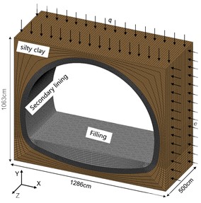
Based on the indoor model test, ANSYS was used to establish the 3D numerical model as shown in Fig. 10, with the model size of 12.86 m×5 m×10.63 m (length×width×height), the thickness of the tunnel lining structure is 50 cm, and the surrounding is powder clay. SOLID units were used for the lining structure and powder clay, and beam units were used for the lining reinforcement. cm-g-μs unit system. Vertical restraint is applied at the bottom of the model, horizontal restraint is applied at both sides of the model longitudinally, and uniform load is applied at the top and both sides of the model, with vertical uniform load q of 0.265 MPa and horizontal uniform load e of 0.133 MPa.
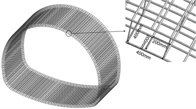
By the tunnel lining structure design, lining reinforcement was set in the secondary lining as shown in Fig. 10, with a 20 mm diameter of circumferential and longitudinal main reinforcement, and 200 mm spacing; 8 mm diameter of hook reinforcement and 400 mm×400mm spacing.
Fig. 10Numerical calculation of the overall model
5.1.2. Numerical calculation parameters
The model has four materials: C25 concrete, C15 concrete, pulverized clay, and lining reinforcement, and the appropriate material model is selected for parameter setting based on the relevant material models provided by ANSYS. The MAT_DRUCKER_PRAGER material model was used for the powder clay around the lining in the model test. According to the results of the indoor mechanical parameter tests, the model material parameters are shown in Table 3.
5.1.3. Numerical calculation reliability verification
To verify the reliability of the numerical calculation parameters, the same locations as the indoor model test stress measurement points Y1-Y7 were selected in the disease-free lining numerical calculation model, and the stress data were counted and multiplied by the stress similarity ratio of 10 and compared with the model test for analysis, as shown in Table 4.
From Table 4, the maximum error of 12.2 % between the numerical calculation and the model test for the circumferential and longitudinal stresses at measurement points Y1-Y7 is the same, which shows that the material parameters of the numerical calculation and the selection of the algorithm are more reasonable.
Table 3Numerical calculation of model material parameters
Model materials | / (g·cm-3) | / GPa | / MPa | / ° | |
C25 concrete | 2.5 | 28 | 0.2 | – | – |
C15 concrete | 2.3 | 22 | 0.16 | – | – |
Powdery clay | 1.98 | 0.1 | 0.32 | 0.035 | 19 |
Lining steel | 7.8 | 210 | 0.3 | – | – |
Table 4Numerical calculation and model test monitoring point data
Monitoring points | Circumferential stress (MPa) | Longitudinal stress (MPa) | ||||
Model test | Numerical calculation | Error % | Model test | Numerical calculation | Error % | |
Y1 | –0.049 | –0.043 | –12.2 | –0.008 | –0.008 | 0 |
Y2 | –0.588 | –0.576 | –2.0 | –0.117 | –0.117 | –4.1 |
Y3 | 0.036 | 0.034 | –5.6 | 0.036 | 0.036 | –5.3 |
Y4 | 0.506 | 0.496 | –2.0 | 0.101 | 0.101 | –6.5 |
Y5 | 0.038 | 0.034 | –10.5 | 0.036 | 0.036 | –10.0 |
Y6 | –0.59 | –0.576 | –2.4 | –0.117 | –0.117 | –3.3 |
Y7 | –0.045 | –0.043 | –4.4 | –0.008 | –0.008 | –11.1 |
5.2. Numerical simulation of working condition design
To study the mechanical behavior of the lining under the influence of circumferential cracks of different lengths of the lining, the numerical calculation conditions were designed as shown in Table 5.
To study the lining mechanical behavior under the influence of a different numbers of circumferential cracks in the lining, the numerical calculation conditions were designed as shown in Table 6.
Table 5Numerical calculation conditions of annular cracks of different lengths in the lining
Work conditions | 1 | 2 | 3 |
Location of cracks | Null | Vault | Vault |
Crack size (length × width × depth) (cm3) | 0 | 100×0.5×20 | 200×0.5×20 |
Work conditions | 4 | 5 | 6 |
Location of cracks | Vault | Vault | Vault |
Crack size (length × width × depth) (cm3) | 300×0.5×20 | 400×0.5×20 | 500×0.5×20 |
Table 6Numerical calculation conditions for different numbers of circumferential cracks in the lining
Work conditions | 1 | 2 | 3 | 4 |
Location of cracks | Null | Vault | Vault | Vault |
Crack size (length × width × depth) (cm3) | 0 | 500×0.5×20 | 500×0.5×20 | 500×0.5×20 |
Number of cracks | 0 | 1 | 2 | 3 |
Table 7Numerical calculation of longitudinal cracks in the lining with different numbers of cracks
Work conditions | 1 | 2 | 3 | 4 |
Location of cracks | Null | Vault | Vault | Vault |
Crack size (length × width × depth) (cm3) | 0 | 500×0.5×20 | 500×0.5×20 | 500×0.5×20 |
Number of cracks | 0 | 1 | 2 | 3 |
To study the mechanical behavior of the lining under the influence of a different numbers of longitudinal cracks in the lining, the numerical calculation working conditions were designed as shown in Table 7.
5.3. Mechanical behavior of tunnel lining structure under the influence of cracks
5.3.1. Mechanical behavior of tunnel lining under the influence of circumferential cracks of different lengths
The maximum principal stress state of the lining structure changes significantly due to the existence of the crack at the top of the arch. the maximum principal stress clouds at the top of the arch in the calculation conditions of the 100 cm, 300 cm and 500 cm length annular cracks are shown in Fig. 11(a), (b) and (c). The peak range of the maximum principal stress is marked in the figure. The existence of cracks changes the maximum principal stress distribution, and the influence range increases with the increase of crack length; the peak maximum principal stress appears on both sides of the cracks and is symmetrically distributed along the cracks, and the range of peak maximum principal stress does not change significantly with the increase of crack length; the peak maximum principal stress shows an increasing trend with the increase of annular crack length, and compared with the disease-free calculation condition, the peak maximum principal stresses at 100 cm, 300 cm and 500 cm cracks show an increasing trend. The peak maximum principal stresses in the 100 cm, 300 cm, and 500 cm cracks increased by 7.11 %, 17.19 %, and 27.67 %, respectively, compared with the disease-free condition.
Fig. 11Maximum principal stress cloud at the top of the lining vault
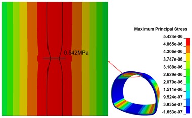
a) 100 cm crack calculation condition
b) 300 cm crack calculation condition
c) 500 cm crack calculation condition
5.3.2. Mechanical behavior of tunnel lining under the influence of the different numbers of circumferential cracks
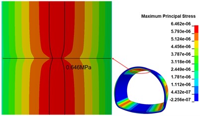
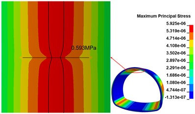
When there are two 500 cm×0.5 cm×20 cm cracks in the inner arch of the lining wall, the maximum principal stress distribution in the inner arch of the lining wall is shown in Fig. 12(a), compared with the calculated working condition of one circular crack, the maximum principal stress distribution in the crack area changes as the number of cracks increases; the maximum principal stress peak is distributed in the middle of the two cracks, and the maximum principal stress peak is 0.673 MPa, compared with the disease-free The maximum stress peak is 0.673 MPa in the middle of the two cracks, which is 37.94 % higher than that of the disease-free condition. When there are two 500 cm×0.5 cm×20 cm cracks in the arch of the lining wall, the maximum principal stress distribution in the arch of the lining wall is shown in Fig. 12(b), relative to the calculated working condition of two circular cracks, with the increase of the number of cracks, the maximum principal stress distribution in the crack area further changes, and the overall symmetrical distribution along the middle crack; the maximum principal stress peak is distributed between two cracks, and the range appears The maximum principal stress peak value is 0.698 MPa, which is 30.33 % higher than that of the disease-free calculation condition.
Fig. 12Maximum principal stress cloud at the top of the lining vault
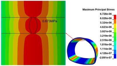
a) 2 cracks calculated working condition
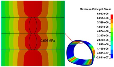
b) 3 cracks calculated working condition
5.3.3. Mechanical behavior of tunnel lining under the influence of the different numbers of longitudinal cracks
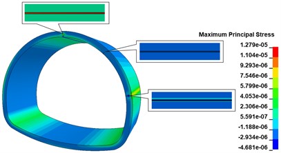
When there is a 500 cm×0.5 cm×20 cm longitudinal crack at the top of the inner wall vault of the lining, the maximum principal stress cloud diagram of the lining is shown in Fig. 13(a), comparing with the disease-free calculation condition, the existence of the longitudinal crack only changes the maximum principal stress distribution at the location of the crack, and there is no obvious change at other locations; the stress concentration phenomenon appears obviously at the bottom of the crack, and the maximum principal stress peak is 1.257 MPa, comparing with the disease-free calculation condition. The maximum stress peak is 1.257 MPa, which is 148.42 % higher than the calculation condition without disease, and the distribution range is the bottom of the crack. As shown in Fig. 13(b), when there are 500 cm×0.5 cm×20 cm longitudinal cracks in both the vault and shoulder of the lining wall, the maximum main stress peak still appears at the vault crack, and the appearance of the shoulder crack does not cause any obvious stress change in the lining structure. When there are 500 cm×0.5 cm×20 cm longitudinal cracks in the lining wall vault, arch shoulder, and arch waist, the maximum main stress cloud of the lining is shown in Fig. 13(c). The increase of the arch waist cracks does not cause significant changes in the stress state of the lining structure, but only causes large tensile stresses in the arch waist behind the lining. When there are 500 cm×0.5 cm×20 cm longitudinal cracks in the inner wall of the lining, arch shoulder, arch waist, and side wall, the maximum principal stress cloud of lining is shown in Fig. 13(d), the peak of maximum principal stress of the lining is 1.306 MPa, which is increased by 158.10 % compared with the calculation working condition without disease, distributed at the bottom of arch crack; the maximum principal stress at the bottom of arch shoulder crack is in a compressed state; the bottom of arch waist crack is in a compressed state; the maximum principal stress at the bottom of arch waist crack is in a compressed state. The maximum principal stress at the bottom of the crack at the arch shoulder is compressed, the maximum principal stress at the bottom of the crack at the arch waist is compressed, the two sides of the crack are in tension, and there is a concentration of tensile stress at the arch waist behind the lining, with the maximum principal stress value of 7.256 MPa; the maximum principal stress at the bottom of the crack at the foot of the arch is compressed, the upper side is in tension, and the lower side is in compression.
Fig. 13Lining maximum main stress cloud
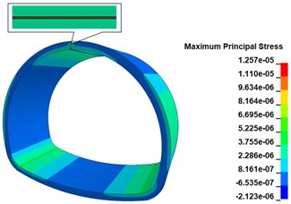
a) 1 crack calculation working condition
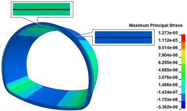
b) 2 cracks calculation working condition
c) 3 cracks calculated working condition
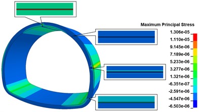
d) 4 cracks calculated working condition
6. Conclusions
Based on the detection of lining damage in the Wushan Tunnel, this paper identifies the lining of a class V surrounding rock highway tunnel as the research object, and conducts a more in-depth study of the lining structure stress behavior and lining damage evolution law under the influence of lining cracks through a combination of indoor model tests and numerical calculation models, with the following main research results:
1) When cracks exist in the inner wall of the lining vault, the stress state of the lining changes, mainly manifesting as an increase in circumferential and longitudinal tensile stresses at the vault, while the stress state at other locations of the lining remains unchanged.
2) When the length of circumferential cracks, longitudinal cracks and the number of circumferential cracks in the inner wall of the lining vault increase, the circumferential, and longitudinal tensile stresses at the lining vault show an increasing trend, where the stress effect from the change in the length of longitudinal cracks is greater than that of circumferential cracks.
3) When circumferential cracks appear in the vault of the lining wall, the stress state of the lining will change relative to that of a disease-free tunnel, and the maximum principal stress peak will appear near the cracks; the increase in the length of the circumferential cracks will lead to an increase in the maximum principal stress peak in the lining, which basically will not change the maximum principal stress peak range; the increase in the number of circumferential cracks will only cause a slight increase in the maximum principal stress peak, but will significantly change the maximum The increase in the number of circumferential cracks only causes a slight increase in the peak maximum principal stress, but will significantly change the peak maximum stress range.
4) When longitudinal cracks exist in the lining wall, the longitudinal cracks at the top of the arch have the greatest influence on the stress state of the lining, followed by the waist of the arch, the shoulders of the arch, and the side walls are the smallest; with the increase of the number of longitudinal cracks, the increase of the peak maximum principal stress of the lining is not obvious.
References
-
G. Xu, C. He, Z. Chen, C. Liu, B. Wang, and Y. Zou, “Mechanical behavior of secondary tunnel lining with longitudinal crack,” Engineering Failure Analysis, Vol. 113, p. 104543, Jul. 2020, https://doi.org/10.1016/j.engfailanal.2020.104543
-
S. Xu et al., “Diseases failures characteristics and countermeasures of expressway tunnel of water-rich strata: A case study,” Engineering Failure Analysis, Vol. 134, p. 106056, Apr. 2022, https://doi.org/10.1016/j.engfailanal.2022.106056
-
T. F. Yuan, “A reserch on the impact of the tunnel lining cracing on the structure force performance,” Beijing Jiaotong University, Beijing, 2019.
-
Zhao Yc et al., “Analysis of the impact of a railway tunnel lining cracks on structural safety,” Construction and Design for Engineering, 2022, https://doi.org/10.13616/j.cnki.gcjsysj.2022.09.025
-
L. Xiong, N. Jiang, C. Zhou, and H. Li, “Dynamic response characteristics of adjacent tunnel lining under blasting impact in subway connecting passage,” International Journal of Protective Structures, Vol. 14, No. 1, pp. 87–106, Mar. 2023, https://doi.org/10.1177/20414196221083687
-
X. Z. Liu, P. Zhang, and M. Zhou, “Analysis of effect of longitudinal cracks on bearing capacity of tunnel lining,” Chinese Journal of Rock Mechanics and Engineering, Vol. 31, No. 10, pp. 2096–2102, 2012, https://doi.org/10.3969/j.issn.1000-6915.2012.10.015
-
G. Xu, C. He, D. Lu, and S. Wang, “The influence of longitudinal crack on mechanical behavior of shield tunnel lining in soft-hard composite strata,” Thin-Walled Structures, Vol. 144, p. 106282, Nov. 2019, https://doi.org/10.1016/j.tws.2019.106282
-
J. Yu, “Study on the influence of stress distribution law by lining crack in highway tunnel,” China Civil Engineering Journal, Vol. 50, pp. 70–75, 2017.
-
X. Liu, “Study on crack evolution of subway tunnel lining structure and its influence on structural safety,” Beijing Jiaotong University, Beijing, 2018.
-
W. L. Song et al., “Case study on failure characteristics of highway tunnel based on self-made test platform,” China Journal of Highway and Transport, Vol. 32, No. 1, pp. 117–126, 2019.
-
H. W. Huang et al., “Numerical analysis of tunnel lining crack based on extended finite element,” Chinese Journal of Geotechnical Engineering, Vol. 35, No. 2, pp. 266–275, 2013.
-
F. Zhang et al., “Numerical analysis of crack cracking process of tunnel lining based on fdem,” Chinese Journal of Geotechnical Engineering, Vol. 38, No. 1, pp. 83–90, 2016, https://doi.org/10.11779/cjge201601008
-
W. Song, H. Lai, Y. Liu, W. Yang, and Z. Zhu, “Field and laboratory study of cracking and safety of secondary lining for an existing highway tunnel in loess ground,” Tunnelling and Underground Space Technology, Vol. 88, pp. 35–46, Jun. 2019, https://doi.org/10.1016/j.tust.2019.02.018
-
D. Liu et al., “Experimental and numerical investigation on cracking mechanism of tunnel lining under bias pressure,” Thin-Walled Structures, Vol. 163, p. 107693, Jun. 2021, https://doi.org/10.1016/j.tws.2021.107693
-
“Specifications for Design of Highway Tunnels Section 1 Civil Engineering,” JTG 3370.1-2018, Ministry Of Transport of The People’s Republic Of China, 2019.
About this article

The authors have not disclosed any funding.
The datasets generated during and/or analyzed during the current study are available from the corresponding author on reasonable request.
Zhao Dongkui contributed to the conception of the study. Zhou Huan performed the experiment. Sun Wenchang contributed significantly to analysis and manuscript preparation. Huang Yiwen performed the data analyses and wrote the manuscript. Jiang Nan helped perform the analysis with constructive discussions.
The authors declare that they have no conflict of interest.
