Abstract
Robot-assisted reduction of pelvic fracture requires large workspace and large load capacity. A kind of six degree-of-freedom (DOF) robot for pelvic fracture reduction is designed, which is a hybrid configuration composed of three-revolute-revolute-revolute (3RRR) parallel mechanism and three-dimensional guide rail. The hybrid configuration can ensure that the robot meet the needs of large workspace and large load capacity. Through the comparative analysis of dynamic and virtual prototype simulation, the reduction force of the designed reduction robot can reach 200 N. The experimental results show that the robot not only has the characteristics of high precision and high load of parallel robot, but also has the characteristics of large workspace of series robot.
Highlights
- A 6-DOF hybrid reduction robot for pelvic fractures is proposed, which is a hybrid configuration composed of 3RRR parallel mechanism and three-dimensional guide rail.
- Robot workspace can reach ±30° on each axis, meeting the needs of pelvic fracture reduction.
- The feasibility of the robot is evaluated in virtual prototype simulation and experimental test, in which an external load force of up to 200N is applied by weight.
1. Introduction
Pelvic fractures are one of the most complex and serious fractures in traumatic orthopedics. Pelvic fractures can account for approximately 3 %-8 % of all fractures in the body [1] and are usually caused by high-energy trauma, such as road traffic accidents, crush injuries, and falls from height, resulting in injury to the unstable anterior and posterior pelvic rings, causing complete or incomplete displacement of one or both pelvises, and the difficulty of treatment depends on the direction of fracture displacement as well as the degree of complexity. The commonly used methods for pelvic fracture reduction are external fixation frame treatment [2], incisional reduction and internal fixation, and percutaneous minimally invasive screw internal fixation [3].
However, there are still some disadvantages of traditional pelvic fracture surgical reducing methods, including anatomical reduction, large trauma area, easy infection, soft tissue damage, inaccurate repositioning techniques, intraoperative x-ray exposure with radiation, high surgical intensity, poor healing, and unsatisfactory later recovery. Therefore, with the development of medical robotics, the pelvic fracture reduction robot has been applied to pelvic fracture reduction surgery. This robot has the advantages of accurate positioning, smooth operation, dexterity, large working range, radiation resistance, and infection resistance in surgery, and can achieve higher accuracy, reliability, and precision than traditional manual surgical reduction [4] under the same circumstances.
The difficulties involved in reduction a pelvic fracture are mainly because the pelvis is surrounded by multiple muscles and bones, and the pelvic reduction workspace influenced by muscles and bones. In addition, surgeons and medical personnel often need to apply significant reduction forces to reduction the pelvis, which increases the risk of muscle overstretching and leads to unnecessary soft tissue strain. The workspace of a pelvic fracture reduction robot can be obtained from a statistical survey of pelvic fracture patients conducted by physician researchers [5], which found that the affected side of the pelvis rotates and moves with respect to the healthy side of the pelvis with a maximum offset of ±30° and ±50 mm in three directions. Reduction forces for pelvic fracture reduction are difficult to obtain from experimental studies, and pelvic fractures have some similarities to long-bone fractures, so the load capacity requirements for pelvic fracture reduction robots can be obtained by reference to studies of long-bone fractures. In long-bone fracture reduction, some researchers have attempted to use improved robots for fracture reduction. Ioannis Georgilas et al. [6] used a robotic system for long bone fracture surgery studied in a robotic laboratory to perform soft tissue traction in and around the proximal femur and reduction of femoral neck fractures, and recorded the maximum reduction force and reduction moment during fracture manipulation, and their experimental results showed a maximum reduction force of 604.53 N and a maximum reduction torque value of 13.33 N.m. Giulio Dagnino et al. developed a robotic system for femoral surgery reduction[7]-[9], which is based on a 6-degree-of-freedom (DOF) Stewart robot configuration and is able to achieve precise positioning in its workspace (±10.25 mm along , and ±15 mm along , with a rotation limit of ±17° per-axis). The numerical magnitude of the load was 16.3 N of reduction force and 1.4 N.m of reduction torque, which is significantly lower than in a real fracture surgery due to the lack of real soft tissue in its pelvic model. In 2017, the team improved the structure of its robot by adopting a tandem-parallel structure and an additional traction device, a mechanism capable of controlling two six-degree-of-freedom parallel robots for more complex reduction surgical operations, experiments were conducted using human cadavers for reduction measurement experiments, which showed a maximum robot output force of 157 N and an output torque of 7.43 N.m. In addition, Qing Zhu et al. [10]-[11] developed a sensor-based system to detect forces and moments during the treatment of femoral stem fractures, including the monitoring of reduction forces during the entire process from reduction intramedullary nail placement and fixation. The measurements showed that, based on a local co-ordinate system located at the center of the fracture, a maximum force of 203 N was determined along the -axis, 517 N along the -axis, 505 N along the -axis and a maximum torque of 16.4 N.m calculated along the -axis and 38.3 N.m along the -axis. The measurement system provides surgeons with real-time information, which can help doctors to reduction fractures within the safe range of applied force and torque. A new robotic system for long-bone reduction was developed by Mohammad H. et al. [12]-[14], who designed a new six-degree-of-freedom open-loop resetting robotic system for long-bone fracture reduction. By means of simulation analysis, it was concluded that the robot could carry a load force of 50 kg, and test experiments on cadavers were conducted to demonstrate the high precision and large load capacity performance of the robot.
The majority of fracture reduction studies are still on long-bone fracture reduction, and research on pelvic fractures is still rare. Xu Jiufeng et al. from the Department of Orthopaedics, Yanqing County Hospital, pioneered the use of a six-DOF parallel robot for pelvic fracture reduction [15]. The robot body used a six-DOF Stewart robot, whose robot performance was 50 mm operating range, 1.0 mm positioning accuracy and 490 N reduction operating force. Liu Jixuan et al. from Beijing University of Aeronautics and Astronautics [16]-[17], proposed a new traction method to reduce the reduction force during pelvic reduction, and investigated the performance of the elastic traction method in reducing the reduction force through experimental tests and simulation analysis. The elastic traction method was used to reduce the reduction force more effectively than rigid traction, and the experimental results showed that the reduction force was reduced by 59.2 % when an elastic traction force of 10 kg was applied. In the experiments, the muscle-generated reduction force was approximately 100 N. Zhao Chunpeng et al. [18], from the Orthopaedic Hospital of Beijing Jishuitan Hospital, developed an intelligent robot-assisted fracture reduction system with a tandem-configured UR16e robot. in cadaveric pelvic reduction experiments, the reduction force was generally less than 160 N by the traction device, but considering realistic pelvic patient The actual reduction force would be greater than 160 N [19]. Research into pelvic reduction is still at a single level, failing to take into account the effects of both reduction workspace and reduction forces. It is particularly important to design a pelvic fracture reduction robot that takes into account both the workspace and the load capacity.
Based on the above analysis, the pelvic fracture reduction robot need 6 DOF, and the reduction workspace needs to reach ±30° and ±50 mm. In addition, the load capacity needs to reach 200 N. In order to balance the accuracy, reduction force and workspace, a kind of 6-DOF hybrid pelvic fracture reduction robot is designed. The robot configuration adopts the combination of 3-revolute-revolute-revolute (3RRR) parallel mechanism and three-dimensional (3D) mobile mechanism, which not only has the characteristics of large load of parallel robot, but also has the characteristics of large workspace of series robot. Simulation and experiment show that the robot can meet the reduction requirements of pelvic reduction.
2. Robot architecture
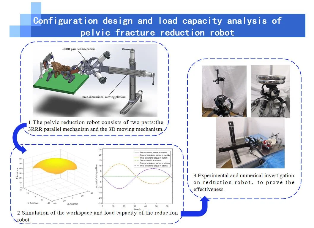
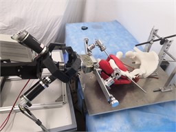
The pelvic reduction robot is shown in Fig. 1, which consists of two parts: the 3RRR parallel mechanism and the 3D moving mechanism. 3RRR parallel mechanism is used for the 3D rotational reduction [20]-[22], and the 3D moving mechanism is used for 3D moving reduction. 3RRR parallel mechanism is fixedly connected to the injured pelvis by a pelvic clamping instrument.
Fig. 1Structure of the pelvic reduction mechanism. Photos owner: Shenyang Cai; location: Shanghai University
(1) 3RRR parallel mechanism.
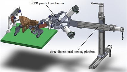
The 3RRR parallel mechanism is composed of a fixed platform, three limbs with same structure, and a moving platform. The moving platform is connected with the fixed platform through three limb. Each limb is composed of three revolute joints connected with upper linkage and lower linkage. Three limbs are symmetrically distributed between the moving and fixed platforms, and all the joint axes intersect at rotation center. The relative motion between each limb of the mechanism is rotating around the center point of the mechanism. As shown in Fig. 2.
Fig. 2CAD model of 3RRR mechanism. Photos owner: Shenyang Cai, location: Shanghai University
(2) 3D moving mechanism.
3D moving mechanism consists of three linear motion units with the same screw guide structure. The motor drives the screw through a coupling, and the trapezoidal nut converts the rotational motion of the screw into linear motion to the sliding stage. In addition, rolling bearings are installed at each end of the screw to carry the axial load as well as the radial load of the screw. Three linear motion units are assembled in separate perpendicular attitudes and are capable of translational motion in three directions.
3. Kinematics analysis of 3RRR mechanism
3.1. Inverse kinematics
Position analysis of the mechanism is to solve the position relationship between the input and output components of the mechanism, which is the most basic task of mechanism motion analysis and the basis of mechanism velocity, acceleration, static analysis, dynamics analysis, etc. The inverse kinematic solution is to solve the position of the input member of the mechanism with the known position and attitude of the output member. In the kinematic analysis of serial mechanism, it is easier to solve the kinematic positive solution and more difficult to solve the kinematic inverse solution, while on the contrary, in the kinematic analysis of a parallel mechanism, the inverse solution is simpler while the positive solution is very complicated. This is the characteristic of parallel mechanism analysis. The kinematic positive and negative solutions of a 6-DOF parallel mechanism have been solved [23]. The inverse solution is more applied in control and subsequent analysis, while the positive solution is less applied. For the convenience of the description, only the inverse solution is derived here in this paper.
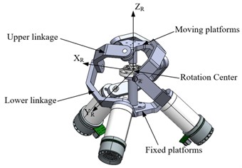
Fig. 3Kinematics of the 3RRR configuration. (Owner: Shenyang Cai, Location: Shanghai University)
As shown in Fig. 3, each vector is defined as follows: ( 1, 2, 3) along the direction, ( 1, 2, 3) along the direction, ( 1, 2, 3) along the direction, where ( 1, 2, 3) are the angle between the projection of of each branch on the lower triangular platform and the projection of the first branch, respectively, ( 1, 2, 3) are the angles between the projection of of each branch on the upper triangular platform and the projection of of the first branch, respectively. is defined as the rotation matrix :
where is and is .
For solving the position inverse solution of the 3-RRR three-DOF spherical parallel robot, it is to solve the input angle of each branch chain when the attitude of the upper platform is known. When , , are known in the Euler angles of the moving platform, the intermediate hinge ( 1, 2, 3) of each branch is connected to the corresponding moving platform ( 1, 2, 3) above the linkage, and the corresponding center angle of the upper linkage is , to establish the constraint equation as follows:
By bringing the above Eq. (1) (2) (4) into this constraint Eq. (5) can be organized as:
And find the input angle of each branch chain:
3.2. Jacobian analysis
The direct derivative method is more commonly used to find the robot Jacobi matrix, which is to derive the Jacobi matrix by directly deriving a constrained relational equation containing input and output angles or displacements for time to obtain the relationship between its input and output angular or linear velocities. Derivation of the above Eq. (5) to time yields:
where and , where is the angular velocity of the moving platform and is the angle of rotation of the drive motor. The final equation can be organized as:
where , and .
3.3. Workspace of 3RRR mechanism
The boundary search method is used for the workspace analysis of the 3RRR mechanism, which is carried out by step-by-step iteration based on the inverse kinematics of the mechanism.
The center of the moving platform is used as the reference point to study the mechanism’s workspace. Under the condition of known mechanism geometric parameters, the boundary search algorithm is used to determine the mechanism's workspace by judging whether a point in the space is within the boundary of the workspace, and the final set of all points obtained is the set of points in the workspace of the mechanism.
3.3.1. Constrained condition
(1) Joint structural constraints.
The constraints of the joint structure make each joint move only within a certain range. For the joints on the static and moving platforms, the lower linkage is not allowed to rotate around the joint axis to the static platform and below, and similarly, the upper linkage is not allowed to rotate around the joint axis to the moving platform plane and above, i.e., it must satisfy:
where and are the projections of and on the -axis of the reference coordinate system, respectively; and are the projections of and on the -axis of the dynamic coordinate system, respectively.
(2) Motor and ball hinge angle constraint.
The interference between the lower link and the intermediate column can be avoided by controlling the magnitude of the angular displacement of the input motor. Assuming that the maximum angle of the input motor is and the minimum angle is , the constraint that no interference occurs between the lower link and the intermediate column is:
Regarding the limitation of the turning angle at the intermediate ball vice, the intermediate ball hinge is procured from QJ20-ZF ball hinge of Hangzhou Guochen Zhengwei Technology Co:
(3) Interference factor between connecting rods.
The minimum permissible distance is dependent on the actual design parameters as the minimum permissible distance depends on factors such as the shape and thickness of the linkage, so this factor is often verified by virtual prototype simulation and is generally ignored during program solving.
3.3.2. Boundary search algorithm
The specific steps of the boundary search method are shown in Fig. 4. Firstly, according to the structural parameters of the parallel mechanism, the maximum reachable boundary of the mechanism workspace is determined. The workspace of 3RRR parallel mechanism is a spherical workspace, so the maximum reachable boundary of 3RRR parallel mechanism is a circular boundary with the spherical hinge as the center and the radius of the sphere as the radius, for ensure that the workspace of the mechanism is within the search space, the selected search element space is set to be larger than the maximum boundary. Next, the above search region is divided into three attitude directions , and . Let , and be the initial spatial points, and divide each attitude direction into equal parts with a step size of . The search is performed by gradually increasing , and when the constraint equation is satisfied, the point is the point in the workspace. Finally, by continuously increasing until the search of all boundaries is completed, the plot obtains the set of all three-dimensional coordinate points in the workspace of the 3RRR parallel mechanism.
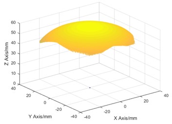
The pelvic reduction robot has 3 linear motion mechanism and 3 rotary motion mechanism. The radius of the sphere of the 3RRR mechanism is 50 mm, the dimensions of the lower and upper linkages are = = 90°, and the thickness of the lower and upper linkages is 10 mm; the geometry of the moving and fixed platforms is = = 45°; the hinge points of the moving and fixed platforms are located at the vertices of the equilateral triangle, the radius of the external circle of the dynamic platform is 32 mm, and its thickness is 10 mm. According to the robot configuration parameters, the range of motion of each joint at the input end of the mechanism is determined. The three-dimensional rotation range is determined by the rotation angles of the three motors of the 3RRR mechanism, and the three-dimensional movement is determined by the rotation angles of the three motors. The above six variables determine the locus of mechanism motion.
As shown in Fig. 5, the inverse kinematic solution of the 3RRR mechanism can calculate the rotation angle of the robot rotational motion component in the and directions as –30°~30°, and the rotation angle in the direction as –32°~32°. The travel of the 3D moving platform is 200 mm, i.e., the robot's workspace contains at least a 200 mm × 200 mm × 200 mm cube.
Fig. 4Boundary searching method flow chart. (Owner: Shenyang Cai; Location: Shanghai University)
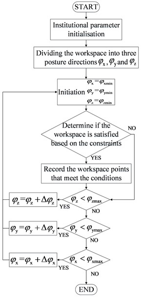
Fig. 53RRR workspace. (Owner: Shenyang Cai; Location: Shanghai University)
4. Dynamic analysis of 3RRR mechanism
The dynamics of the 3RRR parallel mechanism is modeled using the Lagrangian method [24]-[25].
The Lagrangian equation is:
where is the difference between the kinetic energy and potential energy of the Lagrangian function of the system, the kinetic energy and potential energy include the moving platform and the three limb, as generalized coordinates, . is the equivalent moment, where is the motor driving moment, is the Jacobi matrix, and m is the external load moment of the system.
The 3RRR parallel mechanism is decomposed into two subsystems, the moving platform and the three limb. The kinetic energy and potential energy of the two subsystems are solved separately, and then the kinetic equations of the whole mechanism are derived.
Let the angular velocity of the moving platform be , then its kinetic energy and potential energy are:
where is the mass of the moving platform, is the rotational inertia of the moving platform, and the linear velocity of the moving platform , . Then the Lagrangian function of the moving platform is:
Let the angular velocity of the connecting limb be and (including the upper linkage and lower linkage), then the kinetic and potential energy of the connecting limb is:
where (1, 2, 3) and ( 1, 2, 3) are the masses of the th the upper linkage and lower linkage, ( 1, 2, 3) and ( 1, 2, 3) are the rotational inertia of the th the upper linkage and lower linkage, the linear velocity of the th lower linkage ( 1, 2, 3), the linear velocity of the ith upper linkage ( 1, 2, 3), and and are the mass center position vectors of the th upper linkage and lower linkage. The resulting Lagrangian function of the connecting limb is:
Then the Lagrangian dynamics equation of the 3RRR parallel mechanism:
5. Dynamic simulation of 3RRR mechanism
3D model of the 3RRR parallel mechanism is established in software Adams. The simulation model of the pelvic fracture reduction parallel mechanism is established, material properties and movement are added, fixation and joint constraints are added. According to the large reduction force for pelvic fracture reduction, an external load force of 200 N was added to the 3RRR parallel mechanism, and the moment input curve of the 3RRR parallel mechanism in the working range was obtained and theoretical comparison analysis was carried out to verify the correctness of the theoretical analysis of pelvic fracture reduction dynamics, the specific simulation flow The simulation flow is shown in Fig. 6.
Fig. 6Flow chart of 3RRR virtual prototype simulation. (Owner: Shenyang Cai; Location: Shanghai University)
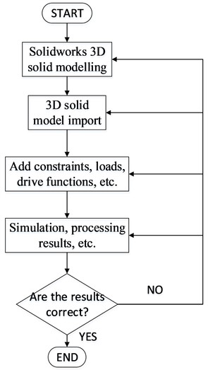
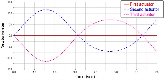
The 3D model is built in SOLIDWORKS, and imported into the Adams. The constraints are applied on the model, as shown in Fig. 7. As the pelvic fracture reduction force should no less than 200 N. Therefore, in the dynamic simulation, the structural parameters and kinematic parameters of the model are set, and the external load force [0 0 200 N] is added to the moving platform. The position input of the moving platform is given as [30sin(time), 0, 0]. After dynamic simulation, the driving torque of each driving limb are shown in Fig. 8.
Fig. 73RRR Virtual prototype model. (Owner: Shenyang Cai; Location: Shanghai University)
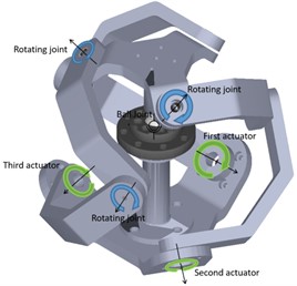
Fig. 8Output torque of each motor. (Owner: Shenyang Cai, Location: Shanghai University)
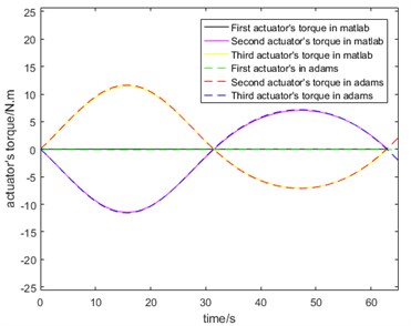
The simulation results are compared with the theoretical calculation results, are shown in Fig. 9. By comparing the results of theoretical calculation with the results of curve simulated by virtual prototype, the torque of motor is basically consistent with the extremum and movement trend of curve simulated by virtual prototype, which verifies the correctness of theoretical analysis. The 3RRR parallel mechanism can bear 200 N reduction force in the workspace, which shows that the mechanism can meet the needs of pelvic fracture reduction in terms of load capacity.
Fig. 9Comparison of theoretical calculation and simulation. (Owner: Shenyang Cai; Location: Shanghai University)
6. Experimental study
6.1. Rotating range of 3RRR mechanism
The workspace test platform of pelvic fracture reduction robot is built. The experimental platform is composed of upper computer, 24 V power supply, motor driver, optical navigator NDI, 3RRR parallel mechanism and so on. The control signal instruction is output by the visual interface of the upper computer of the computer and the feedback data of NDI (Navigation Display Indicator) optical navigation is collected. Through communication bus module, the control signal is sent to the driver of the brush motor, thus controlling the reduction speed and position of the pelvic fracture reduction robot and realizing the movement of the pelvic fracture reduction robot.
Fig. 10x-axis ±30° rotation. (Owner: Shenyang Cai; Location: Shanghai University)
a)-axis +30° rotation
b)-axis –30° rotation
Fig. 11y-axis ±30° rotation. (Owner: Shenyang Cai; Location: Shanghai University)
a)-axis +30° rotation
b)-axis –30° rotation
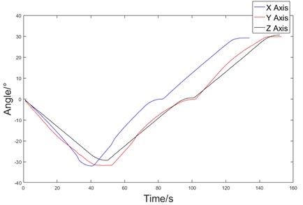
The workspace test is based on the above device, and the position and posture of the robot are measured by NDI optical navigator. The Euler angle of the robot moving in each axis is measured by NDI optical navigator, and the data is transmitted to the upper computer to convert the robot moving angle through rotation matrix transformation.
The range of motion of the 3RRR mechanism is tested. The ranges of mechanism rotation around all three axes are ±30° with a speed of 3~5°/s. The test results of rotation around , , and axes are shown in Fig. 10, Fig. 11 and Fig. 12, respectively.
Fig. 12z-axis ±30° rotation. (Owner: Shenyang Cai; Location: Shanghai University)
a)-axis +30° rotation

b)-axis –30° rotation
The angular displacement rotating around three axes of the moving platform is shown in Fig. 13.
Fig. 13Angular displacement of the moving platform. (Owner: Shenyang Cai; Location: Shanghai University)
6.2. Load capacity of 3RRR mechanism
Set up the pelvic fracture reduction robot load capacity test platform. The whole experimental platform is composed of host computer, power supply, weight, motor driver, guide rail, 3RRR parallel mechanism and so on. The visual interface of the upper computer outputs the control signal instruction and collects the data fed back by the encoder. The control signal is sent to the brush motor driver through the communication bus module, and the driver outputs the current signal to the motor, thus controlling the pelvic fracture reduction robot to execute the movement. As shown in Fig. 14, the motor current of the pelvic fracture reduction robot is measured by applying an external load weight at the end of the 3RRR mechanism, Output motor current size data to the host computer, through the motor torque constant to calculate the motor output torque size, when the motor output torque is less than the motor maximum output torque, the weight of the current weight is the weight of the robot.
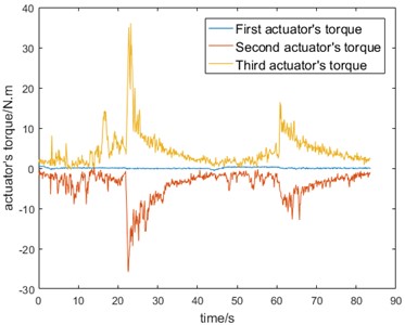
The experimental results are shown in Fig. 15, and the torque change trend of the motor under 200 N load force is consistent with the previous simulation theory. Part of the motor torque peak is due to the motor steering peak torque, the whole does not affect the reduction of the robot. The experimental results show that the 3RRR parallel mechanism moves relatively smoothly under the external load of 200 N, which verifies that the load capacity of the pelvic fracture reduction robot meets the reduction force requirements of pelvic.
Fig. 14Load experiment of 3RRR mechanism. (Owner: Shenyang Cai; Location: Shanghai University)
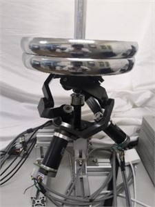
Fig. 15Output torque of each motor. (Owner: Shenyang Cai; Location: Shanghai University)
6.3. Pelvic model experiment
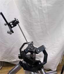
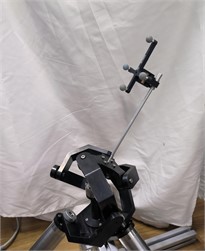
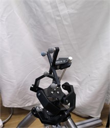
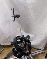
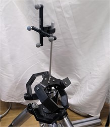
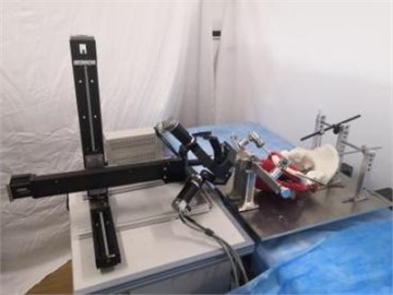
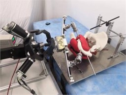
In the next stage, we performed pelvic model experiments to validate the kinematic model and feasibility of the robot. The overall physical replacing robot is shown in Fig. 16. The clamping device can be sterilized to ensure a sterile environment for minimally invasive surgery, and the robot and clamping device are connected by a docking device during the resetting motion. In each test, the robot performs a rotational reset of the pelvis on each axis. Then, the inverse kinematic equations were used to calculate the corresponding joint trajectory of each actuator and generate the actuator position data. These experiments showed reasonably acceptable results. As shown in Fig. 17, the robot can complete the reset demanded rotational range.
Fig. 16Prototype of reduction robot. (Owner: Shenyang Cai; Location: Shanghai University)
The fractures designed in this paper were all Tile C fractures to ensure that the difficulty of experimental repositioning of the specimens was consistent with actual clinical practice. Previous studies have shown that the maximum displacement distance of surgically treatable pelvic fractures is rarely greater than 35 mm [26]; therefore, considering that robot rotation during the resetting process affects the displacement distance, the robot was paired with a guide rail displacement range up to plus or minus 100 mm. but the resetting force carried by the robotic arm is a critical issue. The maximum load of the parallel robot used in this study was 200 N. Clinical experiments on cadaveric specimens with elastic traction resulted in a reset resistance of less than 160 N during the reset process [27], which may be different in clinical situations. The robot load force studied in this experiment can only satisfy the simulated resetting condition, and at a later stage, a resetting robot with more large load capacity will be designed to complete the surgical resetting condition.
Fig. 17Demonstration of pelvic reduction robot. (Owner: Shenyang Cai; Location: Shanghai University)
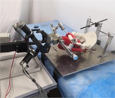
a) Demonstration of -axis rotation reset
b) Demonstration of -axis rotation reset
c) Demonstration of -axis rotation reset
7. Conclusions
As the robot hybrid configuration can achieve a larger workspace and meet the needs of pelvic reduction surgery, A 6-DOF hybrid reduction robot for pelvic fractures is proposed. The boundary search method is used to analyze the robot workspace. In addition, the overall volume of the robot is compact, and the moving platform of the mechanism is lighter, which can meet the requirements of narrow surgical space. The feasibility of the robot is evaluated in virtual prototype simulation and experimental test, in which an external load force of up to 200 N is applied by weight. It is concluded that the pelvic fracture reduction robot has the potential of clinical application, so as to improve the quality of fracture reduction without repeated operation and reduce the radiation amount of operators and patients. In the future, the performance of the robot will be improved, and the path planning program will be designed to achieve the best path, so that the closed reduction surgery has higher accuracy and less soft tissue injury.
References
-
L. Flint and H. G. Cryer, “Pelvic fracture: the last 50 years,” Journal of Trauma: Injury, Infection and Critical Care, Vol. 69, No. 3, pp. 483–488, Sep. 2010, https://doi.org/10.1097/ta.0b013e3181ef9ce1
-
I. Kovler et al., “Haptic computer-assisted patient-specific preoperative planning for orthopedic fractures surgery,” International Journal of Computer Assisted Radiology and Surgery, Vol. 10, No. 10, pp. 1535–1546, Oct. 2015, https://doi.org/10.1007/s11548-015-1162-9
-
H.-S. Liu, S.-J. Duan, S.-D. Liu, F.-S. Jia, L.-M. Zhu, and M.-C. Liu, “Robot-assisted percutaneous screw placement combined with pelvic internal fixator for minimally invasive treatment of unstable pelvic ring fractures,” The International Journal of Medical Robotics and Computer Assisted Surgery, Vol. 14, No. 5, p. e1927, Oct. 2018, https://doi.org/10.1002/rcs.1927
-
S. Joung et al., “A robot assisted hip fracture reduction with a navigation system,” in Medical Image Computing and Computer-Assisted Intervention – MICCAI 2008, pp. 501–508, 2008, https://doi.org/10.1007/978-3-540-85990-1_60
-
A. Khoury, H. Kreder, T. Skrinskas, M. Hardisty, M. Tile, and C. M. Whyne, “Lateral compression fracture of the pelvis represents a heterogeneous group of complex 3D patterns of displacement,” Injury, Vol. 39, No. 8, pp. 893–902, Aug. 2008, https://doi.org/10.1016/j.injury.2007.09.017
-
I. Georgilas, G. Dagnino, P. Tarassoli, R. Atkins, and S. Dogramadzi, “Preliminary analysis of force-torque measurements for robot-assisted fracture surgery,” in 2015 37th Annual International Conference of the IEEE Engineering in Medicine and Biology Society (EMBC), Aug. 2015, https://doi.org/10.1109/embc.2015.7319491
-
G. Dagnino, I. Georgilas, P. Köhler, S. Morad, R. Atkins, and S. Dogramadzi, “Navigation system for robot-assisted intra-articular lower-limb fracture surgery,” International Journal of Computer Assisted Radiology and Surgery, Vol. 11, No. 10, pp. 1831–1843, Oct. 2016, https://doi.org/10.1007/s11548-016-1418-z
-
G. Dagnino et al., “Image-guided surgical robotic system for percutaneous reduction of joint fractures,” Annals of Biomedical Engineering, Vol. 45, No. 11, pp. 2648–2662, Nov. 2017, https://doi.org/10.1007/s10439-017-1901-x
-
G. Dagnino et al., “Intra-operative fiducial-based CT/fluoroscope image registration framework for image-guided robot-assisted joint fracture surgery,” International Journal of Computer Assisted Radiology and Surgery, Vol. 12, No. 8, pp. 1383–1397, Aug. 2017, https://doi.org/10.1007/s11548-017-1602-9
-
Q. Zhu, B. Liang, X. Wang, X. Sun, and L. Wang, “Force-torque intraoperative measurements for femoral shaft fracture reduction,” Computer Assisted Surgery, Vol. 21, No. sup1, pp. 37–44, Dec. 2016, https://doi.org/10.1080/24699322.2016.1240311
-
Q. Zhu, X. Sun, X. Wang, Q. Wu, and B. Liang, “Development of intraoperative noninvasive force measuring system during femoral fracture reduction,” in 2015 IEEE International Symposium on Medical Measurements and Applications (MeMeA), pp. 335–339, May 2015, https://doi.org/10.1109/memea.2015.7145223
-
M. H. Abedinnasab, F. Farahmand, and J. Gallardo-Alvarado, “The wide-open three-legged parallel robot for long-bone fracture reduction,” Journal of Mechanisms and Robotics, Vol. 9, No. 1, Feb. 2017, https://doi.org/10.1115/1.4035495
-
M. H. Abedinnasab, F. Farahmand, and J. Gallardo-Alvarado, “A 3-legged parallel robot for long bone fracture alignment,” in ASME 2017 International Design Engineering Technical Conferences and Computers and Information in Engineering Conference, Aug. 2017, https://doi.org/10.1115/detc2017-67262
-
M. S. Saeedi-Hosseiny, F. Alruwaili, S. Mcmillan, I. Iordachita, and M. H. Abedin-Nasab, “A Surgical robotic system for long-bone fracture alignment: prototyping and cadaver study,” IEEE Transactions on Medical Robotics and Bionics, Vol. 4, No. 1, pp. 172–182, Feb. 2022, https://doi.org/10.1109/tmrb.2021.3129277
-
J. Xu, W. Han, J. Wang, H. Lin, B. Wang, and Y. Feng, “Experimental study of pelvic repositioning robot,” (in Chinese), Chinese Journal of Bone and Joint Surgery, Vol. 8, No. 3, pp. 242–245, 2015, https://doi.org/10.3969/j.issn.2095-9958.2015.03-011
-
J. Liu et al., “An experiment investigation and FE simulation analysis on elastic traction method applied in the pelvic reduction,” in 2021 14th International Congress on Image and Signal Processing, BioMedical Engineering and Informatics (CISP-BMEI), pp. 1–6, Oct. 2021, https://doi.org/10.1109/cisp-bmei53629.2021.9624437
-
J. Liu et al., “Experimental and finite element analysis studies of a reduction-force reducing traction method for pelvic fracture surgeries,” Medicine in Novel Technology and Devices, Vol. 13, p. 100101, Mar. 2022, https://doi.org/10.1016/j.medntd.2021.100101
-
C. Zhao, Y. Wang, X. Wu, G. Zhu, and S. Shi, “Design and evaluation of an intelligent reduction robot system for the minimally invasive reduction in pelvic fractures,” Journal of Orthopaedic Surgery and Research, Vol. 17, No. 1, pp. 1–12, Apr. 2022, https://doi.org/10.1186/s13018-022-03089-2
-
S. P. Parida, P. C. Jena, S. R. Das, D. Dhupal, and R. R. Dash, “Comparative stress analysis of different suitable biomaterials for artificial hip joint and femur bone using finite element simulation,” Advances in Materials and Processing Technologies, Vol. 8, No. sup3, pp. 1741–1756, Oct. 2022, https://doi.org/10.1080/2374068x.2021.1949541
-
H. Saafi, M. A. Laribi, and S. Zeghloul, “Redundantly actuated 3-RRR spherical parallel manipulator used as a haptic device: improving dexterity and eliminating singularity,” Robotica, Vol. 33, No. 5, pp. 1113–1130, Jun. 2015, https://doi.org/10.1017/s0263574714001751
-
H. Saafi, M. A. Laribi, and S. Zeghloul, “Optimal torque distribution for a redundant 3-RRR spherical parallel manipulator used as a haptic medical device,” Robotics and Autonomous Systems, Vol. 89, pp. 40–50, Mar. 2017, https://doi.org/10.1016/j.robot.2016.12.005
-
H. Saafi, M. A. Laribi, and S. Zeghloul, “Forward kinematic model resolution of a special spherical parallel manipulator: comparison and real-time validation,” Robotics, Vol. 9, No. 3, p. 62, Aug. 2020, https://doi.org/10.3390/robotics9030062
-
S. Bai, “Optimum design of spherical parallel manipulators for a prescribed workspace,” Mechanism and Machine Theory, Vol. 45, No. 2, pp. 200–211, Feb. 2010, https://doi.org/10.1016/j.mechmachtheory.2009.06.007
-
G. Wu, S. Caro, S. Bai, and J. Kepler, “Dynamic modeling and design optimization of a 3-DOF spherical parallel manipulator,” Robotics and Autonomous Systems, Vol. 62, No. 10, pp. 1377–1386, Oct. 2014, https://doi.org/10.1016/j.robot.2014.06.006
-
A. Hassani, A. Bataleblu, S. A. Khalilpour, H. D. Taghirad, and P. Cardou, “Dynamic models of spherical parallel robots for model-based control schemes,” arXiv:2110.00491, 2021, https://doi.org/10.48550/arxiv.2110.00491
-
A. J. Starr et al., “Pelvic ring disruptions: prediction of associated injuries, transfusion requirement, pelvic arteriography, complications, and mortality,” Journal of Orthopaedic Trauma, Vol. 16, No. 8, pp. 553–561, Sep. 2002, https://doi.org/10.1097/00005131-200209000-00003
-
Zhao C. et al., “Intelligent robot-assisted minimally invasive reduction system for reduction of unstable pelvic fractures: a cadaveric study,” (in Chinese), Chinese Journal of Orthopaedic Trauma, pp. 372–379, 2022, https://doi.org/10.3760/cma.j.cn115530-20220220-00100
Cited by
About this article

This work was supported by the National Key R&D Program of China under Grant 2020YFB1313803.
The datasets generated during and/or analyzed during the current study are available from the corresponding author on reasonable request.
The authors declare that they have no conflict of interest.
