Abstract
People with walking disorders caused by accidents or stroke can undergo treatment to restore their mobility. Traditional therapy is time-consuming and time-consuming. Therefore, a new trend was born – to facilitate rehabilitation and reduce the patient’s time. Rehabilitation robotics is an area that is constantly evolving, and new mechanisms have recently been developed to help people regain their mobility. This paper presents a 3-RPS parallel manipulator for the restoration of the ankle joint with three degrees of freedom. Parallel manipulator 3-RPS with three degrees of freedom, which was introduced by K. Hunt in 1983 as one of the sedentary parallel manipulators. Since then, 3-RPS has attracted a lot of attention from robotics and biomedical engineering engineers.
Highlights
- The 3-RPS Ankle Rehabilitation manipulator is a robotic device designed to help patients recover from injuries or operations on the ankle joint.
- The device consists of three main components: a rotary joint, a prismatic joint and a spherical joint. These joints work together to provide a range of motion that mimics the natural movement of the ankle joint, allowing patients to perform exercises that help strengthen and repair the joint.
- The 3-RPS Ankle Rehabilitation manipulator has three linear electric actuators that work together to perform ankle joint movements in three different planes of motion: sagittal (front to back), frontal (side to side) and transverse (rotational) planes.
- The device will also later include sensors and control systems that track the patient's progress and adjust the movement of the joints accordingly.
- The 3-RPS manipulator for ankle joint rehabilitation with Raspberry Control is used to control three linear electric drives that make up the 3-RPS manipulator. Raspberry Pi can be programmed to perform certain exercises or movements that help in the rehabilitation of the ankle joint, which makes it a versatile and customizable tool for physiotherapy.
- It is important to note that before developing such a manipulator, it is extremely important to consult with medical professionals and conduct comprehensive testing to ensure the safety and effectiveness of the ankle rehabilitation device.
1. Introduction
The ankle joint is critical to locomotion by sustaining the load of the whole body while exerting key forces during push-off, leg swing, and center of mass advancement during the human gait [1]. Numerous studies have demonstrated that high intensity repetitive movements play an important role in the effectiveness of robotic therapy. Some rehabilitation robots have been developed to treat ankle injuries.
The ankle joint is considered one of the most important structures that support body weight. That is why it belongs to one of the most frequently injured areas in the human body. Every year, millions of people around the world suffer from a fracture or dislocation of the ankle joint.
A fracture of the ankle joint is a violation of bone integrity due to a direct impact or because of indirect mechanisms.
Exercises performed during leg sprains should be long-term, repetitive and with a low load [2]. In this regard, the development and use of active rehabilitation devices is gaining momentum. Active devices for ankle joint rehabilitation can be divided into three categories [3, 4]:
– rehabilitation robots (parallel mechanism robots).
– prostheses and orthoses based on the electric drive.
– energizing exoskeletons.
This article presents a 3-RPS (Revolute – Prismatic – Spherical) manipulator for the restoration of the ankle joint, which consists of three main components: a rotational joint, a prismatic joint, and a spherical joint. These joints work together to provide a range of motion that mimics the natural movement of the ankle joint, allowing patients to perform exercises that help strengthen and repair the joint.
This article is organized as follows. Section 2 describes common injuries of the ankles and feet and their solution, then the design of a robotic device for the ankle joint 3 - RPS, represents the kinematic scheme of a parallel 3-RPS manipulator with 3 degrees of freedom. The conclusion and further work are presented in Section 3.
2. Materials and methods
2.1. Common ankle and foot injuries and their solution
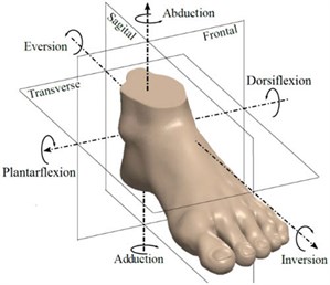
The ligaments of the ankle may be excessively stretched or even torn when the foot is tucked, due to or without external force. Such injuries often occur in sports. Acute ankle injuries are most common. They account for 15 to 20 % of sports injuries. Sports that use frequent, rapid changes in direction, jumps and contact with other players pose a particular risk to ankle ligaments. Football, basketball, and volleyball are sports with particularly high injury rates, such as acute ankle injuries. The risk of repeated ankle injuries is particularly high among athletes. Approximately one third of patients suffer a recurrent ankle injury within three years; 73 per cent of athletes do so. Later, many patients complain of slight swelling in the ankle area, pain during walking and running, swelling and some instability of the ankle joint. 85 % of ankle upper ligament injuries are lateral ligament injuries, of which front lateral ligaments are the most affected. There are also lower ankle injuries. Injuries to only the lower part of the ankle are rare; according to statistics, 10 % of patients with chronic ligament instability of the upper ankle also have instability in the lower part of the ankle.
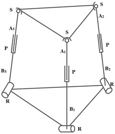
Fig. 1a) Ankle joint and b) ankle planes and movements
a)
b)
Five common injuries to the foot and ankle:
– Achilles Tendonitis or Tear.
– Ankle Sprain.
– Stress Fractures of the Foot.
– Fractures of the Ankle.
– Plantar Fasciitis.
Ankle ligament injuries can be divided into 3 degrees of severity:
– I degree (light).
Ligament sprain without macroscopic rupture, slight swelling and/or sensitivity in the affected structures. Maintenance or minimal loss of function, usually no internal bleeding, no mechanical instability of the ankle, no problems with leg load.
– II degree (intermediate).
Partial macroscopic gap with moderate pain, swelling and sensitivity in affected structures. Slight or moderate impairment of function and mild or moderate instability of the ankle; often internal bleeding and problems with leg load.
– III degree (heavy).
Complete ligament rupture with pronounced edema and hematoma, increased pain sensitivity. Loss of ankle function, as well as pronounced abnormal movements and instability in the ankle, internal bleeding, inability to perform leg load.
Rehabilitation using robotic systems can have many advantages. It allows for more intensive and adapted rehabilitation activities and services (increasing the number and quality of therapy that can be prescribed) and allows all participants involved in the team (for example, physiotherapists, doctors, bioengineers, and others). Set and manage some operational parameters to make rehabilitation specific and optimal for the patient (type of exercise, level of robot assistance, strength, and kinematics that the patient should apply after the exercise).
2.2. Design of the 3 – RPS ankle joint robotic device
The presented robotic device can have a very complex design that drives the ankle joint. A person has many degrees of freedom in his legs, and this condition is difficult or even impossible to correct. The main joint of the foot and ankle joint, each of which provides smooth movements. The forces arising in these joints vary depending on the desired movement. Some movements, such as getting up from a sitting position, require not only significant efforts through the ankle joint, but also Coordination movement of the center of mass of the whole body. The repetition of all these forces and coordination movements is not a normal phenomenon. Thus, to reduce the complexity of the robot manipulator, it is created to bring only certain movements of everyday life [5-6].
The 3-RPS Ankle Rehabilitation manipulator is a robotic device designed to help patients recover from injuries or operations on the ankle joint. The device consists of three main components: a rotary joint, a prismatic joint, and a spherical joint. These joints work together to provide a range of motion that mimics the natural movement of the ankle joint, allowing patients to perform exercises that help strengthen and repair the joint. The device also includes sensors and control systems that track the patient's progress and adjust the movement of the joints accordingly [7, 8].
The 3-RPS parallel manipulator, in which various leg positions are considered (where is rotational, is prismatic and is spherical ligaments, respectively), has so far been studied in detail by many researchers. A 3-RPS parallel manipulator consisting of an equilateral platform was proposed by K. Hunt in 1983 [9-10].
3-RPS in a robot manipulator, only the ankle joint is involved, because it plays a key role in movement, requiring great strength, and is the main support.
The 3-RPS robot manipulator, designed to assist in the event of malfunctions, must be mobile. However, when creating this prototype, the device remains connected to avoid the need to connect wireless or on-board devices. This allows the use of standard controllers and real-time sensors and creates conditions for directing research to the algorithm that forms the basis of the 3-RPS robot manipulator. Like any design process, 3-RPS will have certain parameters that need to be considered and optimized when developing a robot manipulator.
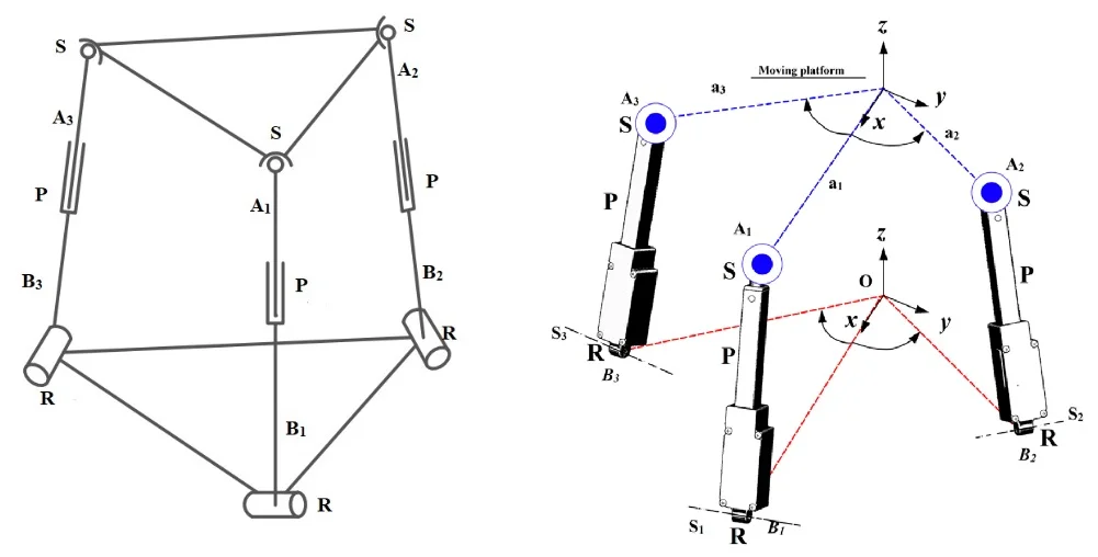
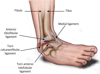
The design of the 3-RPS parallel manipulator studied in this paper is shown in Fig. 2. This manipulator will have three RPS legs. Each foot consists of rotating, prismatic and spherical joints.
An important stage in the study of parallel structure mechanisms is their classification. The most popular are flat, translational-guiding, and spherical mechanisms.
Translational-guiding robotic systems are used in the operations of transferring and manipulating an object. At the same time, orienting movements are often not required, if they are necessary, then one degree of freedom can be added without changing the overall design of the manipulator.
Spherical robotic systems are in demand in processing operations of volumetric curved surfaces. If an additional linear degree of freedom is needed, it can be added without changing the overall design of the mechanism.
Classification of mechanisms for plane, translational and rotational movements was carried out using different groups of screws. To do this, we use the formula:
where – number of degrees of freedom; – the number of connections imposed by the -th kinematic chain, – number of kinematic circuits :
where – the number of intermediate links located between the base and the output link, , , , , – the number of kinematic pairs with 1, 2, 3, 4, 5 mobility in the -th kinematic chain.
Fig. 23-RPS parallel manipulator mechanism
Classification and synthesis of parallel structure mechanisms can be carried out on the basis of Eq. (1), (2). Each kinematic chain contains a drive or imposes connections on the movements of the output link.
The classification is carried out according to the following criteria: the number of degrees of freedom , the number of kinematic pairs, the number of imposed bonds by each chain. The first line indicates the number of kinematic chains and the number of connections imposed by this chain, the number in parentheses indicates the number of drive pairs in kinematic chains under which these numbers are located). Underlined numbers indicate chains with common connections (for spherical – all rotational pairs intersect at one point, for flat – three rotational; one translational two rotational; two translational and one rotational, all rotational are parallel, all translational).
Note that flat, translational-guiding, and spherical mechanisms correspond to closed three-membered groups of screws. In this regard, reduced formulas corresponding to a space equal to three can be used for them.
For the group under consideration, this can be expressed by the structural formula:
where – number of degrees of freedom, – the number of connections imposed by the -th kinematic chain; ; – the number of kinematic circuits.
The value is defined as:
where – the number of intermediate links located between the base and the output link.
Fig. 33-RPS parallel manipulator designs
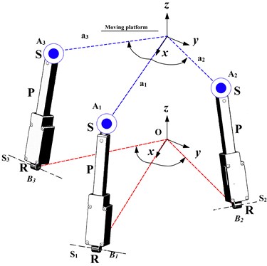
The design of the 3-RPS parallel manipulator studied in this paper is shown in Fig. 3. This manipulator will have three RPS legs. Each foot consists of rotating, prismatic and spherical joints. The axes of the three rotating hinges intersect at point . The coordinate system , , , whose origin is at point O, is defined by as a fixed frame. The base of the manipulator is limited by three rotating joints. Next, we use the projection coordinates to determine the location vectors of points , where 1, 2, 3. It is assumed that point , is located on the axis, 0°, and the coordinates of point and Vector , expressed by , are expressed as follows:
The coordinate system , , , where the coordinate head is located at point , is called , and it is attached to a movable platform. Three spherical joints are located at the top of the movable platform. the center of the spherical joint is denoted as ( 1, 2, 3).
3. Conclusions
Rehabilitation of human legs is becoming an increasingly serious problem in robotics. In this regard, university scientists around the world pay great attention to the development of effective devices to solve this problem. As mentioned in the paper, the human ankle joint is one of the most traumatized parts of the human body. The robotic solutions on the market today are still unacceptable to users because of their cost, size, or complex structure. In this regard, the device should be designed in such a way as to be as compact as possible, suitable for everyday use, and have a longer time of their operation and operation.
Based on these facts, in accordance with the design contract, a parallel 3-RPS manipulator with 3 degrees of freedom was developed, which was used as an ankle recovery device. In future works, the 3-RPS manipulator device for the restoration of the ankle joint used the kinematic optimization method to determine the optimal parameters.
Such a manipulator will be developed for the rehabilitation of the ankle joint by designing and creating a mechanical structure, programming the control system and integrating sensors to measure patient movements and provide feedback to the control system. The manipulator will then be used to give the patient exercises designed to improve the strength and range of motion in the ankle joint.
In further work, the 3-RPS manipulator device was used to restore the ankle joint the three axes of rotation intersect at one point. This point is the center of rotation of the ankle rehabilitation device, and it will be placed as close to the ankle joint as possible. Using Euler parametrization, the size of the base and platform will be synthesized considering its ability to navigate. Features will be a limitation of the synthesis process. In the future, the synthesis method presented in this article will be used, a new 3-RPS parallel manipulator has been created.
It is important to note that before developing such a manipulator, it is extremely important to consult with medical professionals and conduct comprehensive testing to ensure the safety and effectiveness of the ankle rehabilitation device.
References
-
M. Russo and M. Ceccarelli, “Analysis of a wearable robotic system for ankle rehabilitation,” Machines, Vol. 8, No. 3, p. 48, Aug. 2020, https://doi.org/10.3390/machines8030048
-
C. M. Racu Cazacu and I. Doroftei, “An overview on ankle rehabilitation devices,” in Advanced Materials Research, Vol. 1036, pp. 781–786, Oct. 2014, https://doi.org/10.4028/www.scientific.net/amr.1036.781
-
S. Rahman and R. Ikeura, “A novel variable impedance compact compliant ankle robot for overground gait rehabilitation and assistance,” Procedia Engineering, 2012.
-
S. Pittaccio and S. Viscuso, “An EMG-controlled SMA device for the rehabilitation of the ankle joint in post-acute stroke,” Journal of Materials Engineering and Performance, Vol. 20, No. 4-5, pp. 666–670, Jul. 2011, https://doi.org/10.1007/s11665-010-9826-7
-
D. P. Ferris, K. E. Gordon, G. S. Sawicki, and A. Peethambaran, “An improved powered ankle-foot orthosis using proportional myoelectric control,” Gait and Posture, Vol. 23, No. 4, pp. 425–428, Jun. 2006, https://doi.org/10.1016/j.gaitpost.2005.05.004
-
A. Agrawal, S. K. Banala, S. Agrawal, and S. Binder-Macleod, “Design of a two degree-of-freedom ankle-foot orthosis for robotic rehabilitation,” 9th International Conference on Rehabilitation Robotics, 2005. ICORR 2005., 2005.
-
A. Patar, N. Jamlus, K. Makhtar, J. Mahmud, and T. Komeda, “Development of dynamic ankle foot orthosis for therapeutic application,” Procedia Engineering, Vol. 41, pp. 1432–1440, 2012, https://doi.org/10.1016/j.proeng.2012.07.332
-
H. Lee, P. Ho, M. A. Rastgaar, H. I. Krebs, and N. Hogan, “Multivariable static ankle mechanical impedance with relaxed muscles,” Journal of Biomechanics, Vol. 44, No. 10, pp. 1901–1908, Jul. 2011, https://doi.org/10.1016/j.jbiomech.2011.04.028
-
J. Schadlbauer, D. R. Walter, and M. L. Husty, “The 3-RPS parallel manipulator from an algebraic viewpoint,” Mechanism and Machine Theory, Vol. 75, pp. 161–176, May 2014, https://doi.org/10.1016/j.mechmachtheory.2013.12.007
Cited by
About this article

This research has been funded by the Ministry of Science and Higher Education of the Republic of Kazakhstan, Grant No. AP14972221.
The datasets generated during and/or analyzed during the current study are available from the corresponding author on reasonable request.
The authors declare that they have no conflict of interest.
