Abstract
Robotics with exoskeletons has opened a new era of research in the field of modern rehabilitation and assistive technologies. The technology promises to improve the functionality of the upper limbs, which are necessary for daily operations. Exoskeleton technology is developing rapidly but requires interdisciplinary research to solve technical problems such as kinematic compatibility and the development of effective human-robot interaction. This article presents a new design of a device that helps to rehabilitate the upper extremities. The proposed design is characterized by a lightweight structure with an adaptable geometry for various users with low cost and easy to wear characteristics. The CAD model is developed for design details and for modeling, the results of which provide data on the feasibility of the proposed design and its characteristics in the main operational characteristics.
1. Introduction
Currently, rehabilitation technologies are part of strategies that facilitate the integration of people with trauma that generates disability, this is a harmonious understanding of technology, technology, and health [1]. James Reswick describes rehabilitation engineering as the application of science and technology to reduce the limitations of people with disabilities [2]. Rehabilitation engineering is interdisciplinary and unites specialists such as doctors, nurses, physiotherapists, occupational therapists, biologists, engineers, physicists, and chemists. Indeed, rehabilitation devices are developed by a group of specialized professionals with interdisciplinary training, as in the case of bioengineering, which is the application of knowledge gathered in a fruitful balance between engineering and medical science [3]. For this reason, many researchers are currently working intensively on the creation of universal robots that can be worn on the body. Today, research in this area has made it possible to obtain various solid exoskeletons that move synchronously with human limbs. Many of them can support the weight of the human body and even the additional load that comes from lifting weights by a person. In some cases, such exoskeletons can also replace human muscles or bones. However, this type of robot has two obvious drawbacks: it is rigid and very heavy, so a person may have difficulty carrying it. In practice, in addition to this, there are various soft and flexible exosuits that help to perform individual movements of parts of the human body, while consuming less energy. Another advantage of such exo costumes: they do not damage ligaments, tendons, and joints. These robots are capable not only of normalizing partially damaged motor functions, but also of performing lost motor functions, if we take, for example, the elderly or disabled. Another part of people who need exoskeletons includes people with muscle weakness or other degenerative diseases [4].
The goal of this research project is to create one or more complex structures called harmonious exoskeletons that can help people with muscle weakness or other degenerative diseases. In particular, the emphasis is on structures designed to support daily movements of a person with hands (for example, holding a glass of water) and rehabilitation of muscle movements.
This article is organized as follows. The section physical model and design of the human hand describes a methodology that includes the physical model and design of the human hand. The conceptual design section shows the implementation of the methodology for designing an exoskeleton for passive rehabilitation of the upper limb with a detailed description of each stage. The conclusion and further work are presented in Section 3.
2. Materials and Methods.
2.1. Physical model and design of the human hand
The elbow system performs an important function of the ligament, which ensures the correct position of the arms and the transfer of force from the shoulder to the arm. It consists of three bones: the shoulder, elbow, and forearm. However, the hand is made up of three different joints [5-6]:
– shoulder joint.
– elbow joint.
– proximal wrist joint.
They will have a common synovial cavity, which will allow the forearm to expand, stretch and bend, starting at the elbow.
The arm muscles (Fig. 1) are divided into different parts (front and back). Each muscle can cross one or more joints. Table 1 shows all muscle types and their functional functions [7].
Fig. 1Main movements (degrees of freedom) of the upper extremity
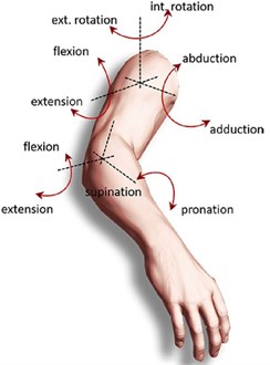
Table 1Arm muscles [8]
Muscle name | Functional activity |
Biceps | Shoulder flexion and elbow flexion and supination |
Shoulder muscle | Elbow flexion |
Biceps shoulder muscle surrounded by shoulder muscles | Shoulder flexion |
Triceps | Shoulder and elbow writing |
2.2. Conceptual design
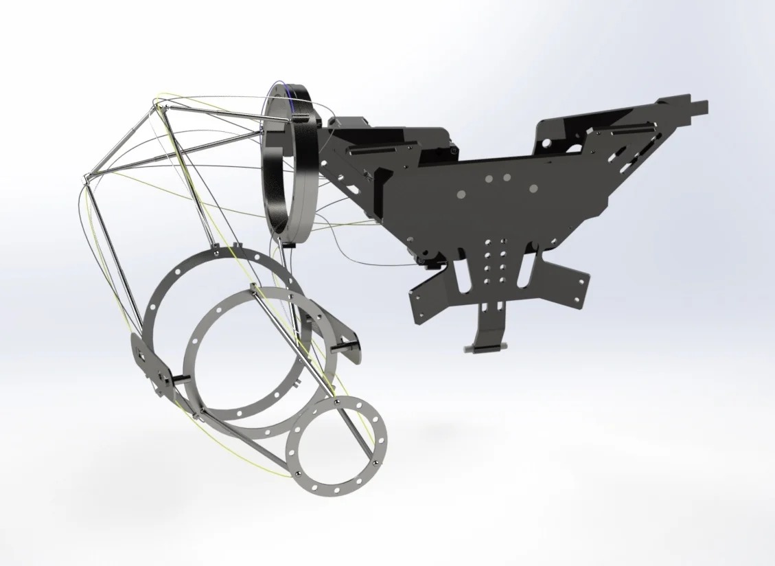
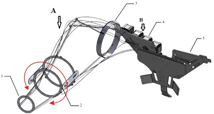
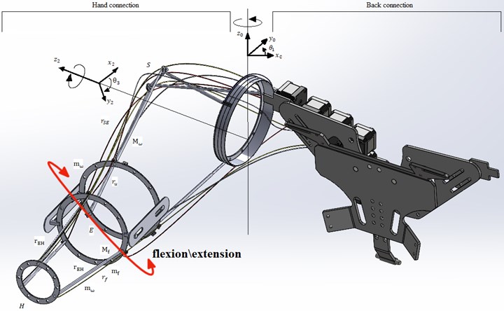
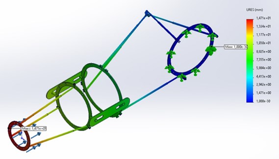
Devices for rehabilitation of the upper extremities were modeled by the SolidWorks program. the shoulder joint, elbow joint and proximal wrist joints consist of a friction ring which is connected by angular articulated joints. Thrust ball bearings are designed to perceive the axial load that connects the two bodies of the exoskeleton, these are a body and . They are available in single and double versions, as well as with spherical lining rings. All devices will be controlled with cable driver. a cable drive system can be used to control the movement of an exoskeleton for the rehabilitation of the upper limbs. the cables are connected to the exoskeleton's joints and are controlled by a motor or other actuator. the movement of the cables can be used to move the exoskeleton's joints and help the user perform exercises to rehabilitate their upper limbs. This type of system can be beneficial for individuals with spinal cord injuries or neurological conditions that affect the upper limbs.
Fig. 2Picture of the Imitation movement flexion and extension: 1 – fixation of the wrist joint, 2 – fixation of the elbow joint, 3 – fixation of the shoulder joint, 4 – cable and control motors, 5 – vest-type suspension system
2.3. Kinematic and simulation results
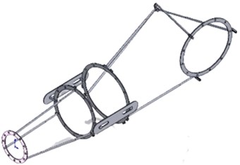
Since the goal of this project is to consider the elbow joint exoskeleton, we assume that the shoulder is in a neutral position, so gravity is not affected and can be ignored. Therefore, this segment can be modeled as a two-link compound.
The kinematic values of the exoskeleton are described in Fig. 3 and are designated as the of the length of the humerus and the of the length of the forearm bone.
The geometry of the human body is considered symmetrical, so the model should be simple. Also, the weight of the cranks is installed on the center lines of the corresponding segments using and. in addition, the mass of the hand is ignored because its mass is negligible compared to the mass of other parts of the hand, and therefore does not give any effect on modeling.
To simulate a human hand, the of the work use the Denavit-Hartenberg parameters Fig. 3. This leads to the emergence of a four – Cartesian coordinate system 0-4, where a system 0 attached to the ground is taken as the beginning of the census, which is considered constant with respect to System 3. to assess the reliability of the device, you need to know the tension during lifting exercises, for example, lifting free weights. in this exercise, the muscles carry a load, the weight of which gradually increases. the load is denoted and is located on the palm of the hand at Point H. the shoulder and forearm masses are constant and are located at the center of mass of the respective parts. Therefore, the potential energy can be calculated as follows:
The vectors and in Eq. (1) can be divided into , x and , , and the other components , , , z and , y, , can be ignored. Then we get the following equation:
The torque on the hinge can be calculated using the formula below:
Fig. 3The kinematic values of the exoskeleton
Since the device is designed for the elbow joint, the moments of other joints are not displayed. Therefore, the generalization of the equation is used only for :
It is necessary to remove this moment from the structure of the exoskeleton being developed. Since the torque of the device varies depending on the conditions of its user, it can also be calculated with this same model. the maximum torque during lifting is achieved when the shoulders are straight. This means that 0 degrees and 90 degrees. the equation for the lifting moment acting on the elbow joint will be as follows:
In Eq. (5), when = 90 degrees are equal, will have a maximum value and depend only on the mass of the hand and the weight of the load:
3D modeling and simulation calculations were carried out in a virtual environment using Solidworks Simulation software and the Motion Simulation package.
Fig. 4 shows the flexion and extension models obtained using Solidworks Simulation. the range of motion in this movement increases from –10 deg to +145 deg, while in imitation it bends up to 9 deg and the opening of the elbow is from 84 deg to 143 deg. Fig. 4 shows the calculation results of the angular acceleration of the platform. This indicated 85-143 mm, describing the movement of the point along the -axis, that is, in 5 s.
The interval of movement during flexion and extension of the elbow is 135 degrees –140 degrees, which in theory includes such an interval.
The simulation in Fig. 4 shows the angular acceleration starting from 0-2.5 seconds 90 degrees, and 2.5-6 seconds shows 140 degrees. This means that this imitation will be very useful for rehabilitation. This is since we have taken into account this therapy used in the rehabilitation of an elbow injury, starting from a small degree rises to a maximum.
Fig. 5 shows the platform speed results. This indicated 210 mm, describing the movement of the point along the -axis i.e., in 5 s.
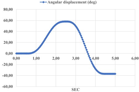
Fig. 6 shows the results of angular displacement of the platform. the angular displacement by which the radius vector has moved when moving the body from point 1 to point 2. This shows 60 degrees describing the movement of a point along the axis, i.e., in 5 seconds.
Fig. 4Angular acceleration of simulated motion in Fig. 3
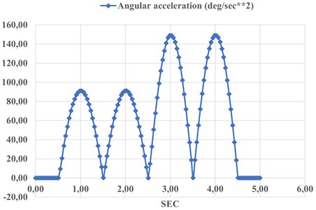
Fig. 5Speed of simulated movement in Fig. 3
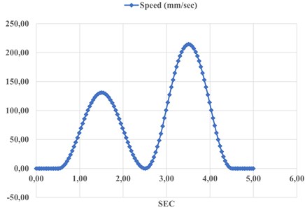
Fig. 6Angular displacement in Fig. 3
Static calculation moving is a vector: two consecutive movements of a particle are equivalent to one movement equal to their vector sum. the module and the direction of the resulting displacement can be according to the known rules of geometry.
Fig. 7Static calculation moving
3. Conclusions
Exoskeleton systems for the upper limbs are needed to help restore movement. in this paper, the physiology of the human upper limb is analyzed. in accordance with the physiological and kinematic characteristics of the upper limb, a new type of robot has been developed for the rehabilitation of the upper limbs.
The model was developed and models in SolidWorks, the results of which are discussed for performance characteristics. a prototype will be assembled to test the new design, and further work will give an experimental characterization. the electronic device for the elbow joint of the hand that we offer is very light, and the control system is very simple.
References
-
G. M. Cruz Martínez and L. A. Z.-Avilés, “Design methodology for rehabilitation robots: application in an exoskeleton for upper limb rehabilitation,” Applied Sciences, Vol. 10, No. 16, p. 5459, Aug. 2020, https://doi.org/10.3390/app10165459
-
J. Enderle, J. Bronzino, and S. Blanchard, Introduction to Biomedical Engineering. Cambridge: Academic Press, 2005.
-
M. Nematollahi, K. S. Baghbaderani, A. Amerinatanzi, H. Zamanian, and M. Elahinia, “Application of NiTi in assistive and rehabilitation devices: a review,” Bioengineering, Vol. 6, No. 2, p. 37, Apr. 2019, https://doi.org/10.3390/bioengineering6020037
-
S. Kim, M. A. Nussbaum, M. I. Mokhlespour Esfahani, M. M. Alemi, B. Jia, and E. Rashedi, “Assessing the influence of a passive, upper extremity exoskeletal vest for tasks requiring arm elevation: Part II – “Unexpected” effects on shoulder motion, balance, and spine loading,” Applied Ergonomics, Vol. 70, pp. 323–330, Jul. 2018, https://doi.org/10.1016/j.apergo.2018.02.024
-
E. Carmeli, S. Peleg, G. Bartur, E. Elbo, and J.-J. Vatine, “HandTutorTM enhanced hand rehabilitation after stroke – a pilot study,” Physiotherapy Research International, Vol. 16, No. 4, pp. 191–200, Dec. 2011, https://doi.org/10.1002/pri.485
-
M. Nilsson, J. Ingvast, J. Wikander, and H. Von Holst, “The Soft Extra Muscle system for improving the grasping capability in neurological rehabilitation,” in 2012 IEEE EMBS Conference on Biomedical Engineering and Sciences (IECBES 2012), pp. 412–417, Dec. 2012, https://doi.org/10.1109/iecbes.2012.6498090
-
M. Bianchi et al., “Design and motion analysis of a wearable and portable hand exoskeleton,” in Biosystems and Biorobotics, pp. 373–377, 2017, https://doi.org/10.1007/978-3-319-46532-6_61
-
B. Kim and A. D. Deshpande, “An upper-body rehabilitation exoskeleton Harmony with an anatomical shoulder mechanism: Design, modeling, control, and performance evaluation,” The International Journal of Robotics Research, Vol. 36, pp. 414–435, 2017.
About this article

The authors have not disclosed any funding.
The datasets generated during and/or analyzed during the current study are available from the corresponding author on reasonable request.
The authors declare that they have no conflict of interest.
