Abstract
The paper proposes a feedback force and velocity control of an arm exoskeleton to assist user motion. The original published control so-called feedback hybrid force and position control was based on the force and position control and was designed to assist user motion. This original control was successful at providing assist for the user’s arm. This article presents an improved control scheme called the feedback force and velocity control. The proposed control is designed to regulate the velocities of joints of the exoskeleton and the feedback forces on links to assist user motion. The design and optimization of the feedback force and velocity control are realized by the Balancing Composite Motion Optimization (BCMO). The numerical method is realized in the paper to show that the proposed control is better than the original control in terms of less oscillation and fast response.
Highlights
- This paper aims to control a four degree of freedom arm exoskeleton using a feedback force and velocity control to support a human user arm motion.
- A human user will exert forces on links to signal the arm exoskeleton to move and it will control feedback forces to support human user arm motion.
- The control gains are optimized using Balancing Composite Motion Optimization and Simulations.
- The new control is better than the previous controls in terms of less oscillation and fast response.
- The interaction forces on links are controlled to track the desired interaction forces.
- The angular velocities of joints are controlled to track the desired angular velocities.
1. Introduction
The paper proposes an arm exoskeleton that can be worn on the human arm, can operate under the control of the user to move in the vertical direction and horizontal direction , and has the ability to provide forces to assist the user motion. We use force sensors in the exoskeleton robot for sensing the feedback forces, and we use actuators for actuating joints. The overviews of the arm exoskeleton robots were introduced in [1-4], and the force control method was developed in [5-9]. The force control is generalized to regulate the feedback force in [10], [11], and [18]. Recently the feedback hybrid force and position control method for assisting the user motion has been published in [12]. Although the force control was successful at controlling all the feedback forces on links, it contained many oscillations and errors. In the other force control design [6], there was a velocity regulator for regulating the angular velocities of joints. The velocities of joints were regulated base on the measured feedback forces. This velocity regulator achieved the desired performances in terms of fast response and less oscillation. In this paper, a feedback force and velocity control is proposed to regulate the velocities of joints of the exoskeleton and the feedback forces on links. The proposed control aims to improve the original control in terms of fast response and less oscillation. A scenario is proposed with two phases [11], [12].
– Phase 1: the user actively exerts forces to signal the arm exoskeleton to generate desired velocities.
– Phase 2: the arm exoskeleton regulates the actuators at joints of the arm exoskeleton to assist the user motion.
The arm exoskeleton makes the following steps: The angles and angular velocities of the joints are ultilized to generalize the desired feedback forces on links while the feedback interaction forces on links are exploited to generalize the desired velocities of links. For assisting the user motion with desired velocities, the proposed arm exoskeleton actuates joints to regulate the feedback forces on the links and the velocities of joints.
The feedback force and velocity control is optimized by using the BCMO [14]. The numerical simulation is realized to show that the proposed arm exoskeleton has achieved the desired performances in terms of less oscillation and fast response.
2. Arm exoskeleton design
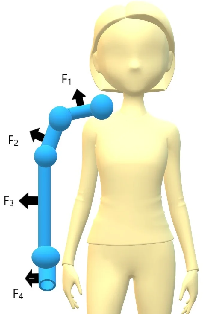
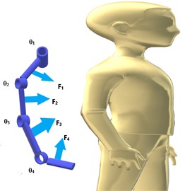
An arm exoskeleton is modelled in the Fig. 1. The arm exoskeleton possesses four joints , , , including two joints at the shoulder , , a joint at the elbow , and a joint at the wrist . It has four links , , , including two shoulder links , , one elbow link and one wrist link . The masses of four links 1, 2, 3, 4 are represented by , , , , respectively. The feedback forces between user and the exoskeleton on the links are , , , . The distance between the vector of forces , , , on the links and the center lines of joints are , , , . The arm exoskeleton possesses four controlled torques , , , at fours joints. The torques at revoluted joints are actuated by the servo motors to support the user.
Fig. 1A model of a 4-DOF arm exoskeleton and user
The Denavite-Hartenberge (D-H) table is provided in Table 1.
Table 1The D-H table
Link | ||||
1-1 | 0 | 0 | ||
1-2 | 0 | 0 | 0 | |
2 | 0 | 0 | ||
3 | 0 | 0 | ||
4-1 | 0 | |||
4-2 | 0 | 0 | 0 |
From the D-H table, the individual homogeneous transformation matrices are obtained by Eq. (1), [15]:
The homogeneous transformation matrix of the end effector is calculated as follows:
3. Feedback force and velocity control
The arm exoskeleton is controlled by the Eq. (3) [6], [12], [16]. The torques at revoluted joints are actuated by the servo motors and the user:
where, (rad); (rad/s); (rad/s2); (Nm) is the vector of torques exerted by the servo motors ; (Nm) is the vector of torques exerted by the user.
The details of matrices in the Eq. (3) are provided in the appendix. The joint damping of joint is expressed as follows [17], [18]:
where, are coefficients of damping of joint (1, 2, 3, 4).
The force control in Eq. (3) contains two phases:
Phase 1: The user actively exert forces to signal the exoskeleton robot to generate the desired velocities.
Phase 2: The arm exoskeleton is actuated to assist the user motion. The feedback force and velocity controller contains two parts. The first part of the control is the force control which controls the feedback interaction forces on the linksto track the desired feedback forces on the links. The second part of the control is the velocity control which controls the feedback velocities of joints to track the desired angular velocities of joints.
Fig. 2Block diagram of the feedback force and velocity control
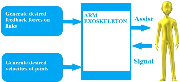
The block diagram of the feedback force and velocity control is explained in Fig. 2. In phase 1, the user exerts forces to signal the arm exoskeleton to generate the desired velocities. In phase 2, the desired feedback forces on the links are generated in Eq. (8). The desired angular velocities of the joints are based on Eq. (12).
The feedback forces on the links 1, 2, 3, 4 can be measured in reality. In numerical method, the user’s forces exerted on the links are modeled in the Eqs. (5), (6):
where, (N/m); (Ns/m); (m); (rad); (rad); (N) is the user force; (N) is the maximum user force on link (1, 2, 3, 4); is the Jacobian matrix; (m); is the rotation matrix; The details of matrices in the Eq. (7) are provided in the Appendix.
In phase 2, the desired feedback forces are generated to assist the user motion as follows [12], [13]:
where, , , are virtual coefficients; (Nm) is the gravitational torque of link (1, 2, 3, 4).
The differences are as follows:
where, is the measured feedback force on the link (1, 2, 3, 4).
In numerical method, the measured feedback forces are modeled as follows:
where, , are disturbances and the forces exerted by the human user, (1, 2, 3, 4), , are the coefficients in the measurement.
The differences are utilized in the force control to actuate joints by using transposed Jacobian matrices as follows:
The feedback force and velocity control is proposed as follows ([19], [20-23]):
where, , are the proportional gains of the feedback force control and velocity control, respectively (rad/s); (rad/s) is vector of the current angular velocities of the exoskeleton at joints 1, 2, 3, 4; (rad/s) is the desired angular velocity of joint ; (rad/s/N) is the coefficient of mobility of the desired motion.
The voltage of servo motor , , (1, 2, 3, 4) are controlled following Eq. (13). In order to stabilize the voltages, the limited voltages are regulated as follows:
where, ; (V); (Nm); (Nm); is the ratio between the output torque and the input torque of the gearbox of the servo motor .
The relationship between the , the output torque generated by servo motor , and the voltage (1, 2, 3, 4), when and negligible, is as follows [24], [25]:
where, (Ω); V/(rad/s); (rad/s); (H); (A); (Nm/A) are explained in the Table 2.
4. Optimal gains of the feedback force and velocity control
To find the optimal gains of the Feedback Force and Velocity control, the parameters of the arm exoskeleton are in Table 2.
Table 2Parameters of a 4-DOF arm exoskeleton
Parameters of the arm exoskeleton | Values |
Link length , , , (m) | 0.2, 0.3, 0.4, 0.2 |
Link mass , , , (kg) | 0.3, 0.5, 0.3, 0.5 |
Distance , , , (m) | 0.2 |
Virtual coefficients (Ns/rad), (N/rad), (1/m) | = 0.5, = 0.5, = 0.5 |
Viscousity damping coefficients , , , (Nms/rad) | 0.3 |
Inertia moments of links (kg.m2) | = |
Inertia moments of servo motors (kg.m2) | = |
Supplied voltage (V) | 12 |
Stiffness , , , (N/m) | 10000 |
Damping , , , (Ns/m) | 100 |
Maximum interaction forces on links (N) | = 2, 3, 2, 1 |
Torque constant parameters , , , (Nm/A) | 0.002, 0.003, 0.002, 0.001 |
Back electro motive force (Voltage) constant parameters , , , (Vs/rad) | 0.001 |
Resistor parameters , , , (Ω) | 3 |
Ratio gearbox parameters , , , | 250 |
Proportional gain of the controller: , | Automatically optimized by BCMO |
Maximum allowed torques , , , (Nm) | 2, 3, 2, 1 |
The disturbance from outside environment (N) | |
The coefficients of the disturbance in the measurements and user’s force, respectively | 1, –1 |
The coefficient of mobility or admittance (rad/s/N) | –0.2 |
Simulation time (s) | 20 |
The desired angles and desired angular velocities of the joints are:
The initial positions and initial angular velocities of the joints are:
In the algorithm, the gains , of the feedback force and velocity control will be optimized to minimize the root mean square of the error in the Eq. (17):
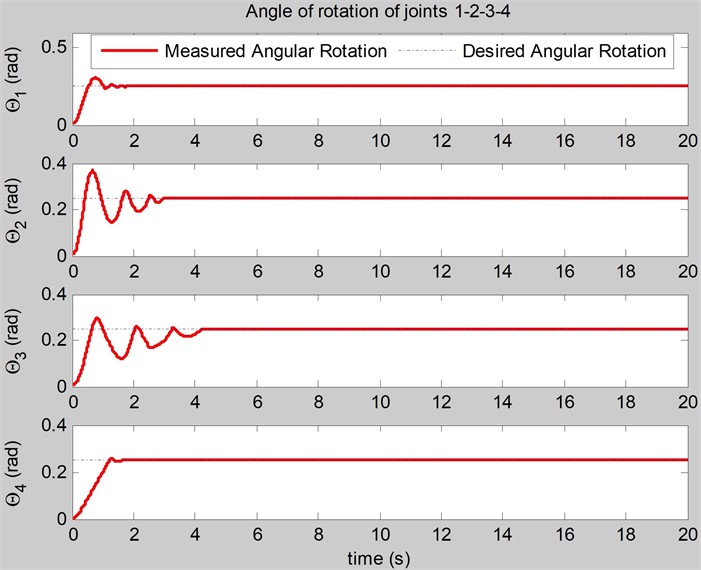
In the algorithm, the initial values are 10, = 50, = 500, 0; the optimal function of BCMO is the. The optimized proportional gains of the feedback force and velocity control are: 48, 394. The optimal = 0.47 (N). The simulations of angles of joints and angular velocities of joints are carried out in Figs. 3, 4. The simulations of the feedback forces on the links are shown in Fig. 5.
Fig. 3The simulation of the angles of joints (rad) realized by the feedback force and velocity control
In case of the original control [12], the optimal gains of the original control obtained by BCMO are: 81, 394. The optimal root mean square of error is: = 0.52 (N). The simulation of angles of joints, angular velocities of joints, feedback forces on the links realized by original control are shown in Figs. 6, 7, 8.
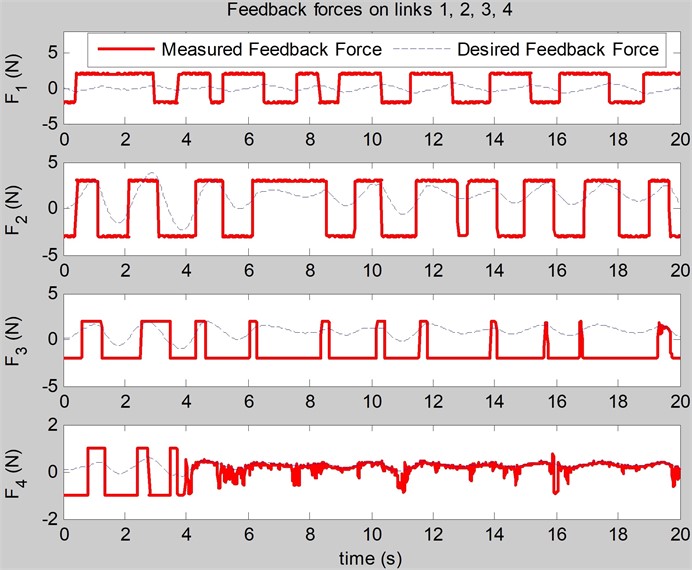
In comparison, the feedback force and position control contains more oscillation in the feedback forces on the links than the feedback force and velocity control contains, and these oscillation in the feedback forces on the links can cause damages to the user. With the proposed feedback force and velocity control, the feedback force control has been improved in terms of fast response and less oscillation when generating safer feedback forces on the links.
Fig. 4The simulation of the angular velocities of joints (rad/s) realized by the feedback force and velocity control
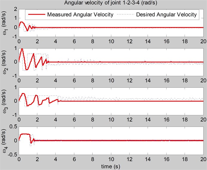
Fig. 5The simulation of the feedback forces on the links (N) realized by the feedback force and velocity control
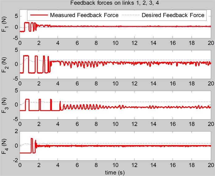
Fig. 6The simulation of the angles of joints (rad) realized by the original control
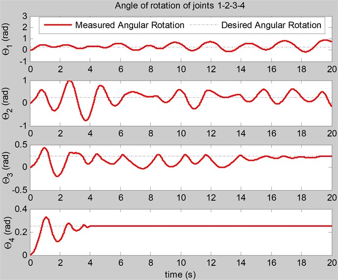
Fig. 7The simulation of the angular velocities of joints (rad/s) realized by the original control
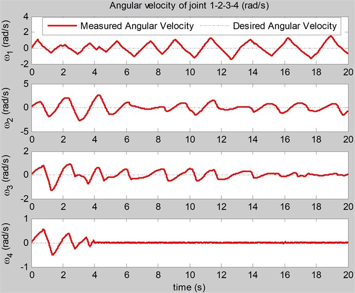
Fig. 8The simulation of the feedback forces on the links (N) realized by the original control
5. Conclusions
In the paper, the feedback force and velocity control to regulate the better feedback forces on the links is realized and optimized by BCMO. The feedback force and velocity control aims at assisting user motions. When the user moves his arm, the arm exoskeleton is actuated to assist his motion. The numerical simulation shows that the feedback force and velocity control has achieved the safer feedback forces on the links in terms of fast response and less oscillation.
References
-
R. A. R. C. Gopura and K. Kiguchi, “Mechanical designs of active upper-limb exoskeleton robots: State-of-the-art and design difficulties,” in IEEE International Conference on Rehabilitation Robotics (ICORR), p. -, 2009.
-
H. S. Lo and S. Q. Xie, “Exoskeleton robots for upper-limb rehabilitation: State of the art and future prospects,” Medical Engineering and Physics, Vol. 34, No. 3, pp. 261–268, Apr. 2012, https://doi.org/10.1016/j.medengphy.2011.10.004
-
J. L. Pons, Wearable Robots: Biomechatronic Exoskeletons. Wiley Online Library, 2008.
-
Khairulanam and A. A. Al-Jumaily, “Active Exoskeleton Control Systems: State of the Art,” in International Symposium on Robotics and Intelligent Sensors 2012 (IRIS 2012), Vol. 41, pp. 988–994, 2012.
-
E. Magrini and A. de Luca, “Hybrid force/velocity control for physical human-robot collaboration tasks,” in 2016 IEEE/RSJ International Conference on Intelligent Robots and Systems (IROS), pp. 857–863, Oct. 2016, https://doi.org/10.1109/iros.2016.7759151
-
C. Silawatchananai and M. Parnichkun, “Haptics control of an arm exoskeleton for virtual reality using PSO-based fixed structure H∞ control,” International Journal of Advanced Robotic Systems, Vol. 16, No. 3, p. 172988141984919, May 2019, https://doi.org/10.1177/1729881419849198
-
C. Silawatchananai and M. Parnichkun, “Force control of an upper limb exoskeleton for virtual reality using impedance control,” in IEEE International Conference on Robotics and Biomimetics, pp. 2342–2347, 2011.
-
H. Kazerooni, “Human robot interaction via the transfer of power and information signals,” IEEE Transactions on Systems, Man, Cybernetics, Vol. 20, No. 2, pp. 450–463, 1990.
-
H. Kazerooni, R. Steger, and L. Huang, “Hybrid control of the Berkeley lower extremity exoskeleton (BLEEX),” The International Journal of Robotics Research, Vol. 25, pp. 561–573, 2006.
-
J. Tang, J. Zheng, and Y. Wang, “Direct force control of upper-limb exoskeleton based on fuzzy adaptive algorithm,” Journal of Vibroengineering, Vol. 20, No. 1, pp. 636–650, 2018.
-
T. C. Nguyen, M. Parnichkun, M. T. T. Phan, A. D. Nguyen, C. N. Pham, and H. N. Nguyen, “Force control of upper limb exoskeleton to support user movement,” Journal of Mechanical Engineering, Automation and Control Systems, Vol. 1, No. 2, pp. 89–101, Dec. 2020, https://doi.org/10.21595/jmeacs.2020.21689
-
T. C. Nguyen, A. D. Nguyen, M. Parnichkun, and M. T. T. Phan, “Feedback hybrid force and position control of an upper limb exoskeleton to support human movement,” Robotic Systems and Applications, Vol. 3, No. 2, pp. 84–97, Dec. 2023, https://doi.org/10.21595/rsa.2023.23623
-
H. J. Lee, K.-S. Kim, and S. Kim, “Generalized control framework for exoskeleton robots by interaction force feedback control,” International Journal of Control, Automation and Systems, Vol. 19, No. 10, pp. 3419–3427, Jul. 2021, https://doi.org/10.1007/s12555-020-0097-2
-
T. L. Duc, Q. H. Nguyen, and H. N. Xuan, “Balancing composite motion optimization,” Information Sciences, Vol. 520, pp. 250–270, 2020.
-
M. W. Spong, S. Hutchinson, and M. Vidyasagar, Robot Dynamics and Control. Wiley, 2004.
-
D. Sanh, D. Phong, and D. D. Khoa, “Motion of mechanical system with non-ideal constraints,” Vietnam Journal of Mechanics, Vol. 35, No. 2, pp. 157–167, 2013.
-
T. Tjahjowidodo, F. Al-Bender, and H. Brussel, “Friction identification and compensation in a dc motor,” IFAC Proc Vol (IFAC-PapersOnline), Vol. 38, No. 1, pp. 554–559, 2005.
-
H. Liu, Y. Liu, and M. Jin, “An experimental study on Cartesian impedance control for a joint torque-based manipulator,” Adv Robot, Vol. 22, No. 11, pp. 1155–1180, 2008.
-
R. P. Borase, D. K. Maghade, S. Y. Sondkar, and S. N. Pawar, “A review of PID control, tuning methods and applications,” International Journal of Dynamics and Control, Vol. 9, No. 2, pp. 818–827, Jul. 2020, https://doi.org/10.1007/s40435-020-00665-4
-
G. Liang, W. Ye, and Q. Xie, “PID control for the robotic exoskeleton: application to lower extremity rehabilitation,” in IEEE International Conference on Mechatronics and Automation, 2012.
-
S. Oh, E. Baek, S.-K. Song, S. Mohammed, D. Jeon, and K. Kong, “A generalized control framework of assistive controllers and its application to lower limb exoskeletons,” Robotics and Autonomous Systems, Vol. 73, pp. 68–77, 2015.
-
M. Hessinger, M. Pingsmann, J. C. Perry, R. Werthschutzky, and M. Kupnik, “Hybrid position/force control of an upper-limb exoskeleton for assisted drilling,” in 2017 IEEE/RSJ International Conference on Intelligent Robots and Systems (IROS), pp. 1824–1829, Sep. 2017, https://doi.org/10.1109/iros.2017.8205997
-
V. Avilés, O. F. Avilés, J. Aponte, O. I. Caldas, and M. F. Mauledoux, “Performance analysis between a hybrid force/position and conventional controllers for a wrist exoskeleton,” Archives of Control Sciences, Vol. 32, pp. 409–427, 2022.
-
S. Centinkunt, Mechatronics. John Wiley & Sons, Inc, 2007.
-
D. G. Alciatore and M. B. Histand, Introduction to Mechatronics and Measurement Systems. New York: McGraw Hill, 2007.
About this article

The paper is supported by Vietnam Academy of Science and Technology (VAST) under grant number CSCL03.03/23-24.
The datasets generated during and/or analyzed during the current study are available from the corresponding author on reasonable request.
Thang Cao Nguyen: modelling, control design; Ngoc Tuan Nguyen: revise, check.
The authors declare that they have no conflict of interest.
