Abstract
Performing heavy physical tasks, overhead work and long working hours are some examples of activities that can lead to musculoskeletal problems in humans. To overcome this issue, automated robots such as the upper-limb exoskeleton is used to assist humans while performing tasks. However, several concerns in developing the exoskeleton have been raised such as the control strategies used. In this study, a control strategy known as the extended de-weight fuzz was proposed to ensure that the exoskeleton could be maneuvered to the desired position with the least number of errors and minimum torque requirement. The extended de-weight fuzzy is a combination of the fuzzy-based PD and fuzzy-based de-weight controller systems. The extended de-weight fuzzy was then compared with the fuzzy-based PD and PID controllers, and the performances of these controllers were compared in terms of their deviations and required torques to perform tasks. The findings show that the proposed control strategy performs better than the fuzzy-based PD and PID controller systems.
1. Introduction
The exoskeleton is one example of an assistive technological innovation. Nowadays, the use of an exoskeleton is not limited to assisting or augmenting human performance [1-4]. In fact, the exoskeleton has been identified as one of the solutions in dealing with muscle fatigue in humans [5-7]. Muscle fatigue can occur at any age group and it is a condition whereby the strength required to perform the tasks is greater than the motion strength of an individual [8, 9]. Several factors that contribute to this problem are heavy physical activities, repetitive work, overhead work, and long working hours [10, 11]. Muscle fatigue can affect the quality of life for workers and there is a high risk of experiencing musculoskeletal disease (MSD) that could degrade their work performance [4, 12-17].
An exoskeleton is classified into three parts, namely the upper-, lower-extremity, and whole-body suits [8, 18]. There are several challenges in developing the exoskeleton, in which one of them is the development of the control system [19]. The control system is used to ensure that the exoskeleton is able to move along with the human upper limb [20-22]. In addition, the control system should be able to interact and respond to movements generated by humans. Since the development of the exoskeleton in this study is to assist humans when they are experiencing fatigue, it is thus essential for the exoskeleton to be able to identify the strength of humans.
The contributions of this work are summarised as follows:
– The proposed extended de-weight fuzzy controller can enhance the limitation of the fuzzy-based PD controller to ensure that the movements of the upper-limb exoskeleton are accurate.
– The proposed extended de-weight fuzzy controller provides an insight into the reduction of errors and torques for the upper-limb exoskeleton.
– The proposed extended de-weight fuzzy controller is also capable of handling disturbance.
2. Research method
The research method comprises the modelling of the human upper-limb and exoskeleton upper-limb. In the first section, the kinematics and dynamics of the upper-limb are presented and followed by the exoskeleton upper-limb.
2.1. Kinematics and dynamics of the human arm
The development of the upper-limb exoskeleton is based on the kinematics and dynamics of the human arm during daily activities. Hence, it is important to know how movement occurs in the human body, specifically the human upper limbs. It is known that the musculoskeletal system comprising the connective tissues, muscles, and joints supports, stabilises, protects, and produces precise movements for the human body.
The human upper limb is designed as segments of linked bones that are linked by joints that have multiple degrees of freedom. The movements of the human upper limb are due to the existence of muscles. Muscles provide power or moment across the joints to enable movement. Some examples of human movements are shoulder flexion/extension, shoulder abduction/adduction, elbow flexion/extension, and wrist flexion/extension.
Fig. 1Shoulder movements: Initial position (Extreme left), (1a) Shoulder abduction, (1b) Shoulder adduction, (2a) Shoulder extension (2b), Shoulder flexion, (3a) Shoulder internal rotation, and (3b) Shoulder external rotation
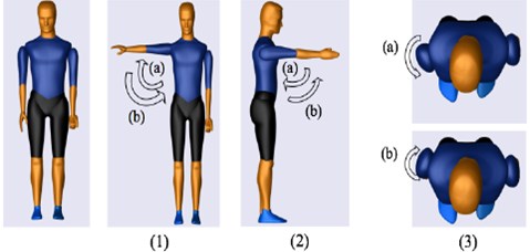
Table 1Basic movements of the upper limb
Joints | Rotation | Translational | |||||
Flex/Ext | Abd/Add | Int/Ext | Pro/Sup | Rad/Ulnar | Up/Down | Fward/Bward | |
Shoulder | / | / | / | / | / | ||
Elbow | / | ||||||
Wrist | / | / | / | ||||
In this study, the development of the exoskeleton is solely based on the daily upper-extremity activities, in which the activities usually comprise combinations of basic movements. The movement combinations are presented in Table 1 and shown in Figs. 1-3. In this study, the shoulder is attached to the body by a ball and socket joint, and this joint is responsible for shoulder flexion/extension, shoulder adduction/abduction, and shoulder internal/external movements (Fig. 1). The upper and lower arm are connected by a single rotating joint known as a revolute joint at the elbow (Fig. 2). The lower arm and the palm are also connected by a revolute joint at the wrist (Fig. 3). The region of rotation for each joint is shown in Table 2.
Fig. 2Initial position (Extreme left) (a) Elbow flexion (b) Elbow extension (c) Forearm pronation (d) Forearm supination
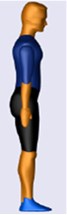
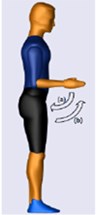
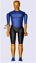
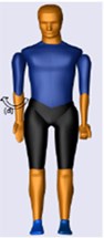
Fig. 3Initial position (Extreme left) (a) Wrist extension (b) Wrist flexion (c) Ulnar deviation (d) Radial deviation
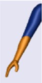
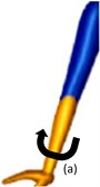
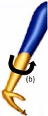
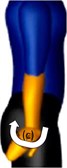
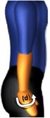
Table 2Range of motion and torques for human upper extremities [10, 23, 24]
Joints | Range of motion | Torque, |
Shoulder flexion | 0-130°/180° | 115° |
Shoulder extension | 0-30°/80° | 110° |
Shoulder abduction | 0-180° | 134° |
Shoulder adduction | 0-50° | 94° |
Shoulder medial (Internal) | 0-60°/90° | 39.2° |
Shoulder lateral (External) | 0-90° | 39.2° |
Elbow flexion | 0-160° | 72° |
Elbow extension | 0-140°/146° | 42° |
Forearm pronation | 0-80° | 9° |
Forearm supination | 0-85° | 7° |
Wrist flexion | 0-90° | – |
Wrist extension | 0-80° | – |
Wrist abduction | 0-30°/40° | – |
Wrist adduction | 0-150° | – |
2.2. Mechanical design of the upper-limb exoskeleton
The design of the exoskeleton used in this study was inspired by the TitanArm due to the simplicity of its design. Moreover, it is capable of powered use and data transmission on a mobile platform [9]. The material used to design the exoskeleton is aluminium as it is a low-density material with reasonable strength characteristics. As mentioned in Section 2.1, the shoulder joint in this study has three degrees of freedom, while the elbow and wrist joints have one degree of freedom, respectively (Fig. 4).
2.2.1. Kinematics of the exoskeleton
Fig. 5 shows the schematic diagram of the exoskeleton and the Denavit-Hartenberg Table for shoulder adduction/abduction movements. The , , , and values represent the base for shoulder internal/external, shoulder extension/flexion, elbow extension/flexion, and the endpoint of the exoskeleton. The homogenous transformation matrix Eq. (1) is used to obtain the position and orientation of the end-effector (), with respect to the fixed reference frame ():
Fig. 4View of the exoskeleton from three perspectives
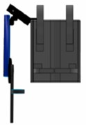
a) Front view
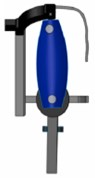
b) Right view
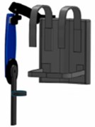
c) Perspective view
Fig. 5a) Schematic diagram of exoskeleton, b) Denavit-Hartenberg table
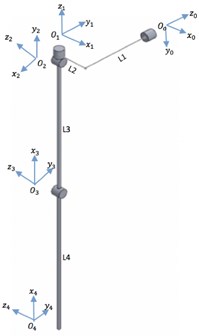
a)
b)
2.2.2. Dynamics of the exoskeleton
The dynamics of the upper-limb exoskeleton was developed using the Euler-Lagrange approach as it is frequently used for the modelling of rigid robotic systems. Euler Lagrange is derived from Lagrangian (). Lagrangian is the difference between the kinetic () and potential () energy:
The total kinetic and potential energy for the whole system is presented as follows:
By applying the partial derivative to Eqs. (3, 4), the dynamic of the whole system is obtained and presented as follows:
The is the exoskeleton inertia matrix, is a matrix containing Coriolis and Centrifugal terms, is a vector containing the gravity term, and is the vector of external torques acting on the actuated degree-of-freedom (DOF). The , and are positions, angular velocities, and angular accelerations of the revolute joints.
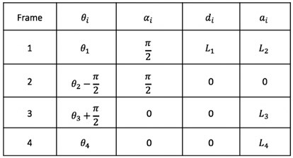
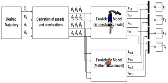
The dynamic model of the whole system was validated by comparing the generated torques between Eq. (5) with the SimMechanics model (Fig. 6). The input to the system is the angular positions of the shoulder and elbow joints for both the flexion and extension movements. The results for the validation process are presented in Section 4.
Fig. 6Validation approach
3. Control strategy
The control design of this study is presented in Fig. 7. A detailed description of the control design is provided in [1, 2].
Fig. 7Control design of the upper-limb exoskeleton
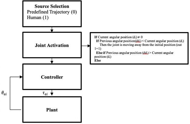
The proposed controller has been previously tested on humans with different strength [1]. In this study, the proposed controller was evaluated with the inclusion of disturbance. The performance of the proposed controller was compared with PID and fuzzy-based PD control. In the next section, the implementation of the PID, fuzzy-based PD, and the de-weight fuzzy controllers are described.
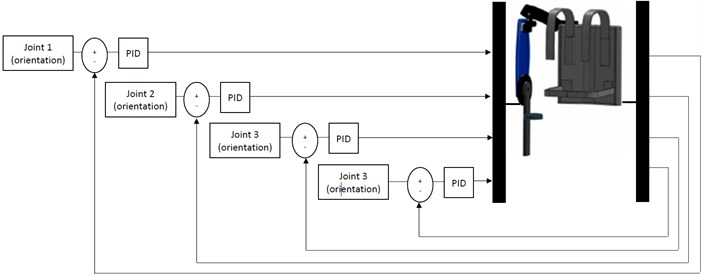
3.1. Implementation of PID control
The PID control was selected as a reference point for comparison as it was simple to implement and reliable. The input to the PID controller is the error of the trajectory. The error is obtained by comparing the actual trajectory from the desired trajectory. The error is then fed into the controller and the necessary torque is generated by the controller. The generated torque is then sent to the motor joint to move or to achieve the desired trajectory (Fig. 8).
Fig. 8Implementation of the exoskeleton with PID control
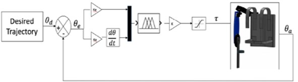
3.2. Implementation of fuzzy-based PD control
The implementation of the fuzzy-based PD control for the exoskeleton is presented in Fig. 9. The combination of fuzzy-based PD was selected due to the ability of PD to minimise the steady-state error and the rise time, thus requiring less power consumption.
The inputs to the fuzzy-based PD control are the trajectory error () and the rate of change of error (). The error is obtained by measuring the difference between the actual trajectory and the desired trajectory, while the rate of change of error is calculated by the derivative of the error. The controller will generate the torque according to the inputs to ensure that the motor joint moves to the desired trajectory.
Fig. 9Implementation of the exoskeleton with fuzzy-based PD control
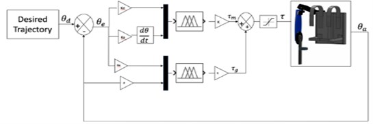
3.3. Implementation of an extended de-weight fuzzy control
The extended de-weight fuzzy controller consists of fuzzy-based PD and fuzzy-based de-weighting control (Fig. 10). The fuzzy-based PD assists the motor joint to move to the desired trajectory, whilst the fuzzy-based de-weighting is used to compensate the gravity torque to increase the smoothness of the movement. The inputs for the fuzzy-based PD is similar to those described in Section 3.2. The inputs for the fuzzy-based de-weight are position error () and the current position of the motor joint (). The torques generated from the fuzzy-based PD and fuzzy-based de-weight are summed up and sent to the motor joint. For both fuzzy-based PD and extended de-weight fuzzy, a saturation block is included to ensure that the inserted torque is within the range of the human torque [22, 23].
Fig. 10Implementation of the exoskeleton with extended de-weight fuzzy control
4. Results and discussion
The experiments and simulations were performed using Simulink and SimMechanics. A computer with an Intel Core i7 @ 2.6GHz processing system with 4G RAM was used to run the experiments and simulations.
4.1. Validation of the dynamic model
As previously described in Section 2.2.2, the inputs to the system were the angular positions of the shoulder and elbow joint. Flexion and extension movements were applied to both joints (Fig. 11).
Fig. 11Angular positions of flexion and extension for shoulder and elbow joints
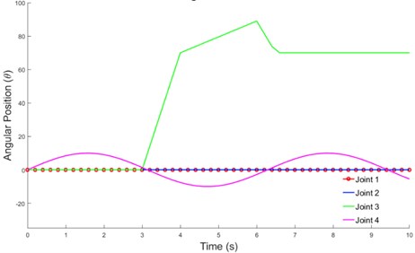
Fig. 12(a-b) shows that although the movement patterns of the velocity and torque required for each joint were similar, they had different values. The torque generated from the mathematical representation (Simulink) was slightly higher than the value obtained from SimMechanics. This could be due to minor differences in the geometrical model built into SimMechanics and parameters described in the mathematical equation [10].
4.2. Observation of control strategies
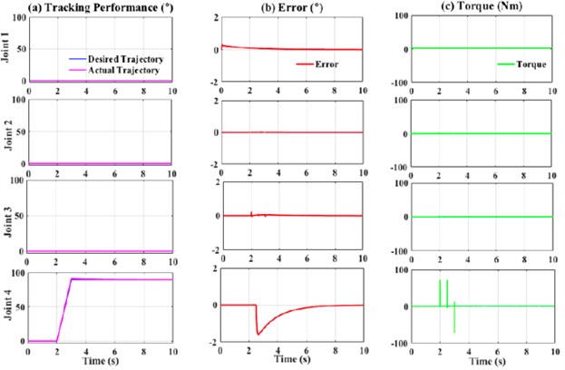
As previously mentioned in Section 3, three types of controllers were used, and their performances were compared. During the experiments, a disturbance was included to validate the stability and robustness of the system. The external forces or disturbance at 1000 Nm were applied at the position shown in Fig. 13 from 2.5 s until 10 s. The external force applied at the forearm was expected to affect the movement of the elbow joint.
Fig. 12Flexion and extension movements: a) velocity and b) torque required
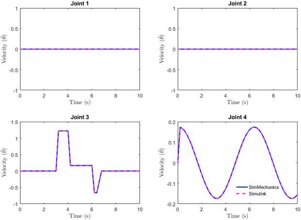
a)
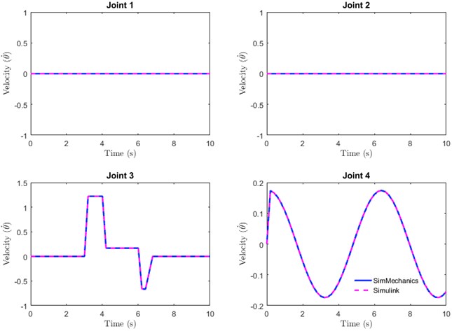
b)
The control parameters used for PID, fuzzy-based PD, and extended de-weight fuzzy are shown in Table 3. These parameters were obtained by heuristic tuning. In general, all the controllers were able to track the desired movements even if a high disturbance was applied to the forearm of the exoskeleton (Figs. 14-16), thus indicating that all the controllers were stable and robust. As mentioned previously, joint 4 was the most affected as the disturbance was applied at the forearm. The observations were performed in two stages. Firstly, the PID and fuzzy-PD controllers in terms of root mean square (RMS) and maximum absolute error (MAE) (Table 4) were observed. As shown in Table 4, the RMS of Joint 4 for PID was slightly higher as compared to fuzzy-PD. In addition, the MAE of PID was almost 50 % higher than the fuzzy-PD. This indicates that the maximum difference between the desired and actual trajectory for fuzzy-PD is better than PID, despite the high disturbance applied to the system.
Secondly, the fuzzy-PD was compared with the control proposed in this study, namely the extended de-weight fuzzy.
Table 3Control parameters for PID, fuzzy-PD, and extended-de-weight fuzzy systems
Control parameters | Joint 1 | Joint 2 | Joint 3 | Joint 4 |
10 | 1.0 | 10 | 100 | |
5.0 | 1.0 | 5.0 | 70 | |
0.1 | 4.0 | |||
1.0 | ||||
0 | ||||
1000 | 1000 | 500 | 500 | |
1.0 | ||||
0 | ||||
1000 | 500 | 500 | 500 | |
1.0 | 1.0 | 5.0 | 20.0 | |
5 | 50 | 3 | 500 |
Fig. 13Exoskeleton: a) exoskeleton movement and b) external disturbance
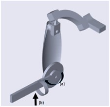
Table 4RMS and MAE of Joint 4
Controller/Joint | RMS | MAE |
PID | 0.3825 | 1.598 |
Fuzzy -PD | 0.3386 | 0.8735 |
Extended de-weight | 0.01802 | 0.03872 |
Fig. 14Performance of PID controller with external force (1000 Nm)
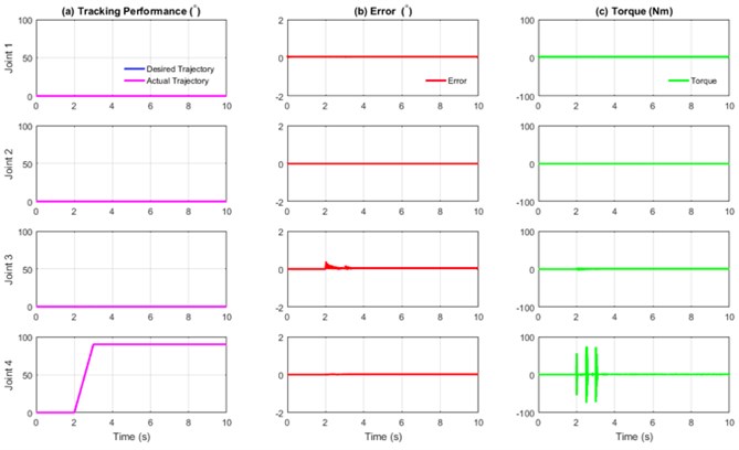
Based on Table 4, the RMS and MAE values for the extended de-weight fuzzy were lesser as compared to fuzzy-PD. This indicates that the combination of fuzzy-based PD and de-weight fuzzy provides a more stable and robust system as compared to the previous study [1, 2]. This observation could be due to the algorithm of the extended de-weight fuzzy itself, in which the value of the actual movements and the error is considered and subsequently added as inputs to the fuzzy. Therefore, when the disturbance was applied, the system could identify that there was a slight uncommon movement from the actual trajectory and hence, corrected the uncommon movement.
Fig. 15Performance of fuzzy-PD controller with external force (1000 Nm)
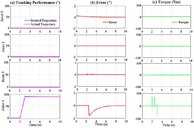
Fig. 16Performance of extended de-weight fuzzy controller with external force (1000 Nm)
5. Conclusions
In this study, an extended de-weight control approach of an upper-limb exoskeleton with control saturation was developed for the joint angle position tracking objective. The de-weight fuzzy control was added to the fuzzy-based PD to compensate for the gravity torque to increase the smoothness of the movement. The robustness of the system was evaluated in this study. Simulation experiments including a comparison with PID and fuzzy-based PD controllers were performed, in which the proposed approach demonstrated satisfactory tracking performance and interaction torque reduction when high amounts of disturbance were applied. Based on these aspects, the performance of the proposed controller outperforms PID and fuzzy-based PD controller. In future experiments, the human fatigue model will be included to observe the robustness of the proposed control system.
References
-
Ali S. K., Tokhi M. O. Control design of a de-weighting upper-limb exoskeleton: extended-based fuzzy. Indonesian Journal of Electrical Engineering and Informatics (IJEEI), Vol. 7, Issue 1, 2019, p. 1-14.
-
Ali S. K., Tokhi M. O. Control design of a de-weighting upper limb exoskeleton. International Conference on Applied Engineering (ICAE), 2018.
-
Ali S. K., Tokhi M. O. Upper-limb exoskeleton for human muscle fatigue. Human-Centric Robotics: 20th International Conference on Climbing and Walking Robots and the Support Technologies for Mobile Machines, Porto, Portugal, 2017, p. 56-62.
-
Ambrosini E., Ferrante S., Rossini M., Molteni F., Gföhler M., Reichenfelser W., Pedrocchi, A. Functional and usability assessment of a robotic exoskeleton arm to support activities of daily life. Robotica, Vol. 32, Issue 8, 2014, p. 1213-1224.
-
Fan L., Yan L., Xiao J., Wang F. Dynamics analysis and simulation verification of a novel knee joint exoskeleton. Journal of Vibroengineering, Vol. 19, Issue 4, 2017, p. 3008-3018.
-
Ochoa Luna C., Habibur Rahman M., Saad M., Archambault P. S., Bruce Ferrer S. Admittance-based upper limb robotic active and active-assistive movements. International Journal of Advanced Robotic Systems, Vol. 12, Issue 9, 2015, p. 117.
-
Theurel J., Desbrosses K., Roux T., Savescu A. Physiological consequences of using an upper limb exoskeleton during manual handling tasks. Applied Ergonomics, Vol. 67, 2018, p. 211-217.
-
Anam, Al Jumaily A.-A. Active exoskeleton control systems: state of the art. Procedia Engineering, Vol. 41, 2012, p. 988-994.
-
Beattie E., Mcgill N., Parrotta N., Vladimirov N. Titan: a Powered, Upper Body Exoskeleton. Retrieved November 22, 2014.
-
Biesiacki P., Mrozowski J., Awrejcewicz J. Study of dynamic forces in human upper limb inforward fall. Dynamical Systems – Applications, Publishing House of Lodz University of Technology, 2015, p. 65-76.
-
Bosch T., Van Eck J., Knitel K., De Looze M. The effects of a passive exoskeleton on muscle activity, discomfort and endurance time in forward bending work. Applied Ergonomics, Vol. 54, 2016, p. 212-217.
-
Carmichael M. G., Liu D., Waldron K. J. Investigation of reducing fatigue and musculoskeletal disorder with passive actuators. IEEE/RSJ International Conference on Intelligent Robots and Systems, 2010, p. 2481-2486.
-
Coffin C. T. The use of a vertical arm support device to reduce upper extremity muscle firing in sonographers. Work, Vol. 42, Issue 3, 2012, p. 367-371.
-
Lalitharatne T. D., Hayashi Y., Teramoto K., Kiguchi K. A study on effects of muscle fatigue on EMG-based con trol for human upper-limb power-assist. IEEE 6th International Conference on Information and Automation for Sustainability, 2012, p. 124-128.
-
Ma L., Chablat D., Bennis F., Zhang W., Guillaume F. A new muscle fatigue and recovery model and its ergonomics application in human simulation. Virtual and Physical Prototyping, Vol. 5, Issue 3, 2010, p. 123-137.
-
Martinez F., Retolaza I., Pujana Arrese A., Cenitagoya A., Basurko J., Landaluze J. Design of a five actuated DoF upper limb exoskeleton oriented to workplace help. 2nd IEEE RAS & EMBS International Conference on Biomedical Robotics and Biomechatronics, 2008, p. 169-174.
-
Xu W., Chu B., Rogers E. Iterative learning control for robotic-assisted upper limb stroke rehabilitation in the presence of muscle fatigue. Control Engineering Practice, Vol. 31, 2014, p. 63-72.
-
De Looze M. P., Bosch T., Krause F., Stadler K. S., O’sullivan L. W. Exoskeletons for industrial application and their potential effects on physical workload. Ergonomics, Vol. 59, Issue 5, 2016, p. 671-681.
-
Huang J., Huo W., Xu W., Mohammed S., Amirat Y. Control of upper-limb power assist exoskeleton using a human-robot interface based on motion intention recognition. IEEE Transactions on Automation Science and Engineering, Vol. 12, Issue 4, 2015, p. 1257-1270.
-
Brahim B., Maarouf S., Luna C. O., Abdelkrim B., Rahman M. H. Adaptive iterative observer based on integral backstepping control for upper extremity exoskelton robot. 8th International Conference on Modelling, Identification and Control (ICMIC), 2016, p. 886-891.
-
Brahim B., Rahman M. H., Saad M., Luna C. O. Iterative estimator-based nonlinear backstepping control of a robotic exoskeleton. International Journal of Mechanical, Aerospace, Industrial, Mechatronic and Manufacturing Engineering, Vol. 10, Issue 8, 2016, p. 1313-1319.
-
Brahmi B., Saad M., Rahman M. H., Ochoa Luna C. Cartesian trajectory tracking of a 7 DOF exoskeleton robot based on human inverse kinematics. IEEE Transactions on Systems, Man, and Cybernetics: Systems, Vol. 49, Issue 3, 2017, p. 600-611.
-
Carignan C., Tang J., Roderick S., Naylor M. A configuration-space approach to controlling a rehabilitation arm exoskeleton. 10th International Conference on Rehabilitation Robotics, 2017, p. 179-187.
-
Gupta A., O’malley M. K. Robotic Exoskeletons for Upper Extremity Rehabilitation. I-Tech Education and Publishing, Vienna, Austria, 2007, p. 371-396.
-
Głowiński S., Krzyżyński T., Pecolt, Maciejewski I. Design of motion trajectory of an arm exoskeleton. Archive of Applied Mechanics, Vol. 85, Issue 1, 2015, p. 75-87.
About this article

This work was supported by Universiti Putra Malaysia and the Malaysian Ministry of Education through Geran Putra – Inisiatif Putra Muda (GP-IPM) (Vot: 9671000) and FRGS/1/2019/ICT02/UPM/02/3.
