Abstract
Based on the topology and mathematical model of the three-phase voltage source PWM rectifier with LCL filter, the resonance produced by the LCL filter and the design method of filter parameters is analyzed. For the resonance problem of the LCL filter, a direct power control strategy of the LCL PWM rectifier based on power damping feedback is proposed. The double-loop control structure is constructed for the inner loop power and outer loop current. The virtual voltage source is constructed as equivalent to power damping in the power loop. The power loop of the output is adopted as a command value in the input current loop, and the current loop is designed to use deadbeat control to ensure the accuracy of current tracking. SVPWM is introduced in this novel direct power control method to generate PWM signals to drive the rectifier power switch and achieve a fixed switching frequency. The experimental results show that this proposed control method can achieve the unit power factor operation of the rectifier while it’s suppressing the resonance, and the system has a better dynamic and static performance.
Highlights
- The power damping feedback is applied to DPC of LCL PWM rectifier.
- The double-loop control for the inner power and outer current is constructed.
- The fixed frequency method is introduced to drive the rectifier power switch.
- Comparative experiments of traditional method show the proposed method better performance.
1. Introduction
Three-phase PWM rectifiers use the single inductor as a filter because the harmonics are generated when the power device is switched. To make the system have better filtering effect, the inductance value is increased. However, the larger the inductance value is, the larger the inductor volume is, and the system costs expensive. Moreover, it will cause the system to degrade in dynamic performance and reduce the response speed of the current loop. The LCL filter has the same total inductance as the single inductance filter, and the impedance value of the LCL filter is inversely proportional to the frequency of the current flowing through it. The higher the frequency is, the smaller the impedance is, which effectively bypasses the high-frequency harmonic components and therefore has better switching harmonic suppression capability [1-6]. Since the LCL filter produces a resonant peak due to its increases capacitance and front inductance, the resonance must be damped. To resolve this problem, many scholars propose a passive damping method and an active damping method [7-10]. Active damping has lower energy loss than passive damping and is suitable for high-power systems.
The common control methods for the PWM rectifier include voltage directional control, model predictive control (prediction of voltage or current), repetitive control, and so on [11-15]. The direct power control (DPC) method directly controls the input power of the PWM rectifier, which has the advantages of high efficiency, fast response, good dynamic and static performance. Moreover, it can realize unit power factor operation [16]. In the traditional direct power control methods, hysteresis comparator and switch table are adopted. Some methods have the optimized double switch table control with enhanced power control and omit the virtual flux direct power control of voltage sensor [17]. However, the above methods are still unable to fix the switching frequency, which is not conducive to the design of the AC side filter. The changing switching frequency will increase the switching loss [18]. At the same time, improper selection of the switching signal will cause power loss control. For grid voltage sensorless control of pulse width modulation (PWM) rectifier under unbalanced network, a closed-loop virtual-flux (VF) estimator is provided to enhance the filtering capability and improve robustness against load variation [19]. Its new idea of an adaptive method can further developed for online frequency estimation. With the direct power control (DPC) scheme, an application of the smooth variable structure filter (SVSF) in the direct power control (DPC) scheme to estimate the instantaneous feedback power and negative-sequence (NS) currents [20]. This new concept of the direct power scheme is modified to cover the injected power to the unbalanced power grid as well.
At present, the main idea of conventional direct power control is to use Space Vector Pulse Width Modulation (SVPWM) to realize fixed-frequency direct power control. However, the direct power control of constant frequency is seldom studied in the LCL-PWM rectifier. The main reason is that the direct power control has no inner current loop, so the existing active damping method cannot be used. In [21], the idea of direct power control with the current loop and the existing active damping method is proposed, but it needs to be added to the extra sensors, and the system is less stable at the same time. According to reference [22], the dynamic characteristics of the PWM rectifier largely depend on the control strategy of the current loop. For the grid-connected, pulse-width-modulator-driven voltage source converters, a novel near-optimal finite-control-set model predictive control (NOP-MPC) algorithm is adopted to progressively synthesize finite sets of virtual voltage vectors (VVs) for the control optimization stage [23]. However, with this method, effects of computational delay, pulse-width modulation delay, and dead-time should be considered and compensated.
A novel direct power control method is proposed based on the instantaneous power theory. The outer power loop’s current inner loop is constructed. The damping power constructed by subtracting the network side current and capacitance current from the power loop is output as the input command value of the current loop. At the same time, the current loop is controlled without a beat to ensure the good dynamic performance of the system. Finally, the required PWM switch signal is obtained after adjustment. In this method, the resonant is damped while the switching frequency is fixed, and the response speed of the system is improved by the direct control of the current. Finally, the system simulation model is built to verify its effectiveness.
2. The principle of DPC method based on power damping feedback
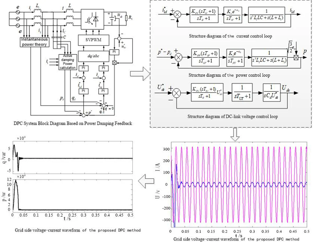
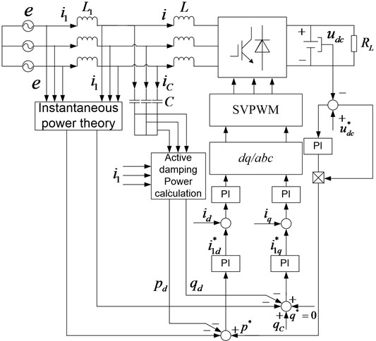
The traditional direct power control strategy uses a hysteresis comparator and a switch table to select the switch signal. Although this method can realize the tracking of active and reactive power, the switching frequency is not fixed, which will increase the switching loss. At the same time, the change of switch frequency makes the connection inductor difficult to design, and the load voltage fluctuates greatly when the load is disturbed. Based on the instantaneous power theory, in this paper, the double-loop control structure is established as shown in Fig. 1. The outer loop adopts the power loop, where the direct power control of the PWM rectifier can be realized by the setting of instantaneous active and reactive power. The control strategy of the current loop determines the dynamic performance of the system to a large extent. If active damping is carried out in the current loop, the system is of poor stability. In this paper, the power damping is constructed in the power loop to suppress resonance, and the current loop is controlled without a beat to ensure the tracking accuracy so that the system has a better dynamic performance.
The system is mainly composed of the power control part, power damping part, and current control part. The reference value of active power is obtained from the dc side voltage, and the reference value of reactive power 0 to realize the unit power factor state operation of PWM rectifier. After subtracting the reference value from the instantaneous active power and reactive power , and then subtracting the active damping power and into PI, the current command values and components are obtained. After comparing with the actual detected network side current, the desired PWM command signal is finally obtained by the PI regulator and inverse transformation.
Fig. 1DPC system block diagram based on power damping feedback
It can be seen from Fig. 1 and instantaneous power theory as follow:
where is the active power on the grid side, is the reactive power on the grid side, when the three-phase grid voltage is balanced, axis coincides with the grid voltage , and 0, , is the voltage amplitude of the grid phase.
Eqs. (1) can also be expressed as follow:
3. The power feedback loop active damping resonance suppression in LCL-PWM rectifier
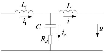
The LCL filter has a better attenuation for the high-frequency harmonic current than the L filter. But because of the addition of the capacitors, the current control system of the rectifier is converted from the first to the third, and it has a harmonic point. It needs to be dumped in the harmonic peak. If only the influence of the harmonic voltage of bridge arm of the LCL-PWM rectifier on each current is studied, then the equivalent circuit of the LCL filter is shown in Fig. 2.
Fig. 2Equivalent circuit of single-phase LCL filter
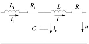
The transfer function from AC voltage to grid-side current of the PWM rectifier can be obtained from Fig. 2.
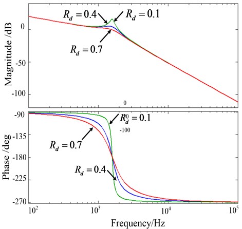
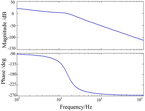
LCL filter parameters are set as: 1 mH, 0.5 mh and 3 F. The Bode graph of is shown in Fig. 3.
Fig. 3Bode plot of LCL filter
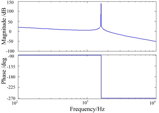
According to Eq. (3), the resonant frequency of the LCL filter is obtained as follow:
At the resonance place, the impedance of the filter is close to zero, which will destroy the stability of the system, so the resonance must be damped. In this paper, the outer loop power and inner loop current are controlled by two loops, and various LCL filter active damping methods can be adopted for both loops. However, the dynamic characteristics of the PWM rectifier in literature [24] largely depend on what kind of current inner loop control strategy is adopted. If the active damping strategy is adopted in the current loop, the dynamic performance of the system will be poor.
The damping power has a direct effect on the power and reactive power. The traditional passive damping is shown in Fig. 4. To clearly show the effect of series resistors of capacitors on the damping effect caused by LCL filters, the parasitic resistors are ignored.
Fig. 4Equivalent circuit with passive damping
According to Fig. 4, the transfer functions of and in passively damped capacitor series resistors can be obtained as follow:
The curve of the Bode diagram at 0.1, 0.4, and 0.7 are respectively shown in Fig. 5.
Fig. 5Bode plot of passive damping at different values
To achieve the same effect as Fig. 5, the equivalent circuit is shown in Fig. 6. is equivalent to a controlled voltage source, where is the feedback coefficient of the capacitor current . This equivalent voltage source provides effective damping at the resonant frequency of the LCL filter.
Fig. 6Passive damping diagram of the equivalent voltage source
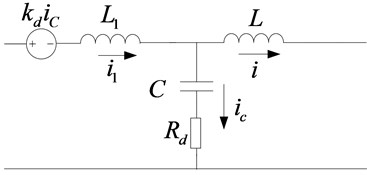
Transfer function of and is obtained as follow:
Let 0, the equivalent circuit is shown in Fig. 7.
Transfer function of and is obtained as follow:
Fig. 7Active damping diagram of the equivalent voltage source
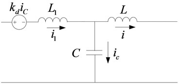
Fig. 8Bode Plot of LCL filter with active damping
Let 0.7, the Bode diagram of is shown in Fig. 8. In the amplitude-frequency characteristic, it can be seen that the resonance peak has been suppressed, and the low-frequency gain section has no attenuation and the active damping is realized. At the same time, the system has a sufficient positive gain margin and a positive phase margin, and the system is stable.
To obtain the equivalent power of the LCL-PWM rectifier for the DPC control, the expected controlled voltage source is multiplied by the grid side current to obtain the amount of power. After the consolidation, the damping components and of active and reactive power are obtained as follow:
where, , , , are component on axis - of and . Active damping is achieved by subtracting and from the active and reactive control loops, respectively.
On the other hand, the LCL filter is required to consume a certain amount of reactive power, so the alternating current needs to make up for the lack of energy in the filter capacitor. Considering that the grid side inductance of is low, it’s an approximation that the filter capacitor voltage is equal to the power grid voltage, which is a non-reactive power that has to be used by a capacitor:
4. The current loop tracking control mode in LCL-PWM rectifier
While the power loop achieves damping resonance suppression, the current-free deadbeat control is introduced to achieve faster tracking control of the current and the system has the good dynamic performance. The mathematical model of the LCL-PWM rectifier switching function under grid voltage balancing can be derived from the switching mathematical model of equations and L-PWM:
where, , and are the DC side voltage, DC side resistance and energy storage capacitance of the rectifier respectively. is the switching function of the rectifier. When 0, the lower bridge arm switch is on and the upper bridge arm switch is off. When 1, it is the opposite. .
For the convenience of analysis, Eq. (10) is rearranged as follow:
If the LCL-PWM realizes the deadbeat control, the line side current and the rectifier AC side current respectively realize the instruction tracking within one cycle:
At the time , the grid side current and the rectifier AC side current command value are given as and . At time , the two currents can be expressed as and .
On the other hand, the sampling frequency of LCL-PWM is much higher than that of the three-phase power source. The three-phase PWM duty cycle can be expressed by the switching function equivalent in one sampling period (). Rearranging Eqs. (10) and (3-12), it is obtained as follow:
Considering the delay of PWM control, it needs to add to in the coordinate transformation to improve the accuracy of control current.
5. The system controller design in LCL-PWM rectifier
In this paper, the double loop control structure of power outer loop and the current inner loop is adopted. The power loop ensures the good dynamic performance of the system. The current loop directly controls the current on the grid side to ensure the current quality of the grid side. To eliminate the resonance of the LCL filter, the instantaneous power tracking signal is obtained by subtracting the power damping link from the active and reactive power commands. Since the active current and the reactive current have the same structure, the design method and parameters are the same, and the active current is taken as an example for design, which is also applicable to the reactive current. The control model of active current is shown in Fig. 9.
Fig. 9Structure diagram of the current control loop
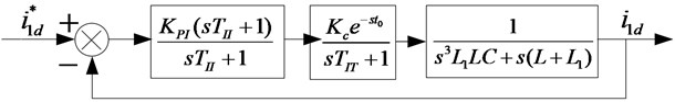
In Fig. 9, the is the current PI regulator proportional coefficient, is the integral time constant, is the PWM rectifier gain, is the rectifier dead time, and is the delay of the rectifier due to control cycle, sampling, and program calculation. The transfer function of the LCL filtering link is obtained as follow:
From Fig. 9, if the power consumption is not counted, let 1, 0, and the current loop is a 5th-order system. Therefore, the method of reference [25] can be used to reduce the order. The pole configuration calculation control parameters are performed. The current loop is replaced by the equivalent time constant first-order inertial link , and the control block diagram of the power loop is shown in Fig. 10.
Fig. 10Structure diagram of the power control loop
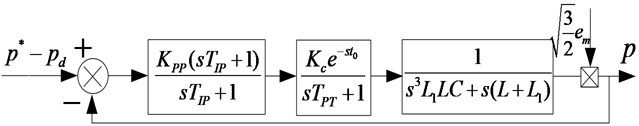
In Fig. 10, is the grid phase voltage amplitude, is the power PI regulation coefficient, is the integration time constant, and is the power loop delay total time constant. The power loop controller parameter design is similar to the current loop. The power loop is represented by the first-order inertia link of the equivalent time constant , and the DC side voltage loop control block diagram can be obtained as follow.
Fig. 11Structure diagram of DC-link voltage control loop
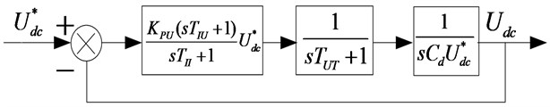
In Fig. 11, is the voltage PI regulation coefficient. is the integration time constant. is the total time constant of the voltage loop delay, and is the DC side voltage filter time constant, . The open-loop transfer function of voltage control is designed as a typical third-order system:
6. Experimental and results analysis
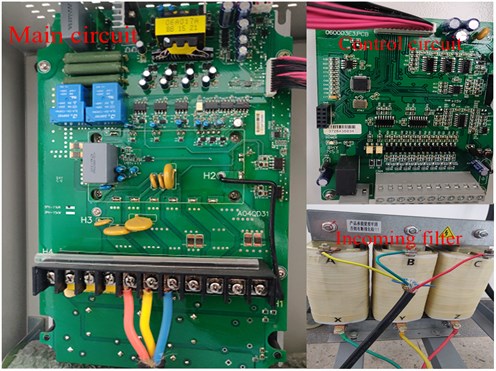
The experimental platform of the PWM rectifier system based on LCL filtering is built, shown in Fig. 12, to verify the effectiveness of the control method proposed in this paper and to compare it with the traditional direct power control. The experimental parameters are as follows: 1 mh, 0.5 mh, LCL filter capacitor 3 μf, three-phase grid AC voltage 220 V, frequency 50 Hz, LCL-PWM rectifier DC side voltage is 600 V, including the switching frequency of 12 kHz.
Fig. 12The experimental platform for PWM rectifier with LCL filter
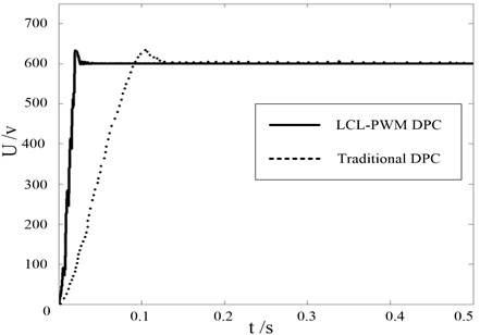
DC voltage waveform of two control methods for the three-phase LCL filter PWM rectifier is shown in Fig. 13. It can be seen that the adjustment time of the DC side voltage of the two control methods is 0.03 s and 0.1 s respectively, and the DC of LCL-PWM DPC based on power feedback is significantly shortened. After reaching the steady-state, the DC side voltage fluctuation is very small, basically stable after 0.04 s and 0.13 s respectively.
Fig. 13DC Side Voltage waveform comparison between LCL-PWM DPC and traditional DPC
One phase of the AC side three-phase voltage is taken as an example, the proposed direct power control can realize in-phase voltage and current on the grid side, shown in Fig. 14. Since the current loop adopts the deadbeat control, the current can achieve accurate tracking and the current distortion on the grid side is small. The transition can be smooth. The system has good dynamic characteristics.
Fig. 14Grid side voltage-current waveform of the proposed DPC method
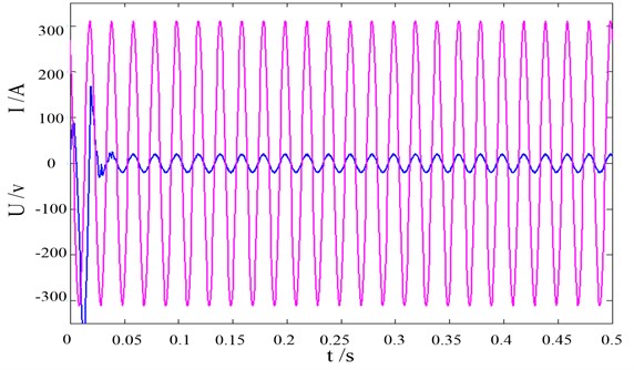
Fig. 15Gird side current harmonic of two control methods
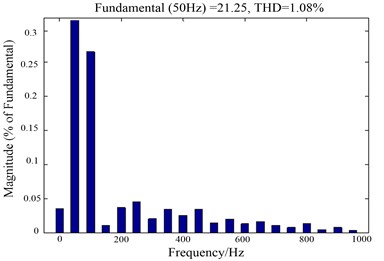
a) LCL-PWM DPC based on power damping feedback
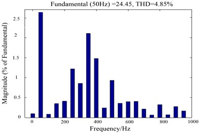
b) Traditional direct power control
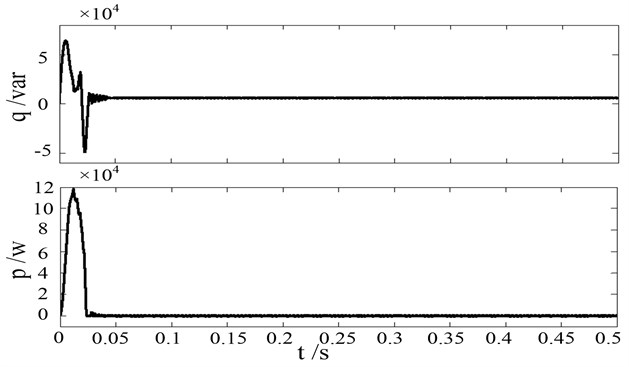
Fig. 16DPC active power and reactive power based on power damping feedback
Harmonic analysis of the grid side currents of the two control methods as shown in Fig. 15, the THD value of the two control methods is 1.08 % and 4.85 % respectively. It can be seen from Fig. 15 that the proposed direct power control method has a lower harmonic distortion rate. And the odd harmonic components are small and there is less pollution to the grid.
The active and reactive power on the grid side is shown in Fig. 16. It is obvious that, the instantaneous active power and the reactive power on the grid side follow the command value, and the power tracking is realized. It can be seen from Fig. 16 that the instantaneous reactive power is substantially zero after the system reaches a steady-state. The unit power factor operation is achieved.
7. Conclusions
Because of the limited applications of the traditional single-inductance PWM rectifier, a new direct power control strategy based on power damping feedback for the LCL filter PWM rectifier is proposed in this paper. The traditional power loop is changed into the current inner loop and the power outer loop. The power damping is introduced into the power loop to suppress the resonance of the LCL filter. With the application of deadbeat control, the inner loop current is directly regulated to generate PWM waves. The experimental results show, compared with the traditional direct power control, the proposed DPCl method has more flexible reactive power control, which suppresses the resonance of the filter. The system has a better dynamic and static performance by fixing the switching frequency.
References
-
Liserre M., Blaabjerg F., Hansen S. Design and control of an LCL-filter-based three-phase active rectifier. IEEE Transactions on Industry Applications, Vol. 41, Issue 5, 2005, p. 1281-1291.
-
Mariethoz S., Morari M. Explicit model-predictive control of a PWM inverter with an LCL Filter. IEEE Transactions on Industrial Electronics, Vol. 56, Issue 2, 2009, p. 389-399.
-
Jeong H. G., Lee K. B., Choi S., et al. Performance improvement of LCL-filter-based grid-connected inverters using PQR power transformation. IEEE Transactions on Power Electronics, Vol. 25, Issue 5, 2010, p. 1320-1330.
-
Reznik A., Simoes M. G., Durra A. A., et al. LCL filter design and performance analysis for grid-interconnected systems. IEEE Transactions on Industry Applications, Vol. 50, Issue 2, 2014, p. 1225-1232.
-
Guzmán R., Vicuna L. G. D., Moraies J., et al. Model-based active damping control for three-phase voltage source inverters with LCL filter. IEEE Transactions on Power Electronics, Vol. 32, Issue 7, 2017, p. 5637-5650.
-
Gomes C. C., Cupertino A. F., Pereira H. A. Damping techniques for grid-connected voltage source converters based on LCL filter: An overview. Renewable and Sustainable Energy Reviews, Vol. 81, Issue 1, 2018, p. 116-135.
-
Mariusz M., Steffen B. A simple voltage sensorless active damping scheme for three-phase PWM converters with an filter. IEEE Transactions on Industrial Electronics, Vol. 55, Issue 4, 2008, p. 1876-1880.
-
Alzola R. P. LCL-filter design for robust active damping in grid-connected converters. IEEE Transactions on Industrial Informatics, Vol. 10, Issue 4, 2014, p. 2192-2203.
-
Leming Z., An L., Yandong C., et al. A single-phase grid-connected power control and active damping optimization strategy with LCL filter. Transactions of China Electrotechnical Society, Vol. 31, Issue 3, 2016, p. 125-131.
-
Hwang P. I., Moon S. I., Ahn S. J. A vector-controlled distributed generator model for a power flow based on a three-phase current injection method. Energies, Vol. 6, Issue 8, 2013, p. 4269-4287.
-
Hu Jiabing, Shang Lei, He Yikang, Zhu Z. Q. Direct active and reactive power regulation of grid-connected DC/AC converters using sliding mode control approach. IEEE Transactions on Power Electronics, Vol. 26, Issue 1, 2011, p. 210-222.
-
Hu YingZhan Research on the system of three-phase VSR PWM rectifier based on SVPWM control. Lecture Notes in Electrical Engineering, Vol. 177, 2012, p. 203-208.
-
Cao Xiaodong, Tan Guojun, Wang Conggang, Li Hao Research on multi-model predictive control strategy of three-level PWM rectifier. Transactions of China Electrotechnical Society, Vol. 29, Issue 8, 2014, p. 142-150.
-
Zhang Yongchang, Peng Yubin, Yang Haitao Performance improvement of two-vectors-based model predictive control of PWM rectifier. IEEE Transactions on Power Electronics, Vol. 31, Issue 8, 2016, p. 6016-6030.
-
Cao Jing, Tong Chaonan, Li Hongtao Hybrid Dual-Loop Control for a Three-Phase PWM Rectifier. Springer Berlin Heidelberg, 2016.
-
Bouafia Abdelouahab, Krim Fateh, Gaubert Jean Paul Fuzzy-logic-based switching state selection for direct power control of three-phase PWM rectifier. IEEE Transactions on Industrial Electronics, Vol. 56, Issue 6, 2009, p. 1984-1992.
-
Toshihiko N., Kohji S. Instantaneous power control of PWM rectifier using hysteresis regulator with frequency characteristic. IEEJ Transactions on Industry Applications, Vol. 128, Issue 8, 2008, p. 1060-1061.
-
Amir B., Abolfazl V., Masoum M. A. S. New switching table for improved direct power control of three-phase PWM rectifier. Australian Journal of Electrical and Electronics Engineering, Vol. 5, Issue 2, 2009, p. 161-167.
-
Yang Haitao, Zhang Yongchang, Liu Jie Frequency-adaptive virtual flux estimator-based predictive power control with suppression of Dc voltage ripples under unbalanced network. IEEE Transactions on Industrial Electronics, Vol. 67, Issue 10, 2020, p. 8969-8979.
-
AlShabi M., Elnady A. Recursive smooth variable structure filter for estimation processes in direct power control scheme under balanced and unbalanced power grid. IEEE Systems Journal, Vol. 14, Issue 1, 2020, p. 971-982.
-
Yuzhou H., Mingyao L., Li H., et al. Triple-state direct power control strategy of three phase boot type PWM rectifiers. Transaction of China Electrotechnical Society, Vol. 28, Issue 5, 2013, p. 208-226.
-
Wu Fengjiang, Wang Zhiwen, Sun Li Improved virtual flux oriented vector control of PWM rectifier. Electric Machine and Control, Vol. 12, Issue 5, 2008, p. 504-508.
-
Lim C. S., Lee S. S., Nutkani I. U., et al. Near-optimal MPC algorithm for actively damped grid-connected PWM-VSCs with LCL filters. IEEE Transactions on Industrial Electronics, Vol. 67, Issue 6, 2020, p. 4578-4589.
-
Pan Donghua, Ruan Xinbo, Wang Xuehua A capacitor-current real-time feedback active damping method for improving robustness of the LCL-type grid-connected inverter. Proceeding of the CSEE, Vol. 33, Issue 18, 2013, p. 1-10.
-
Tan Guojun, Zhao Zhangfei, Yang Baoxin, et al. Study on constant frequently direct power control of three-level PWM rectifier. Power Electronics, Vol. 45, Issue 3, 2011, p. 6-8.
About this article

This work is supported by the National Science Foundation of China (U1704157), National Key Research and Development Program of China (2017YFB0306400), Scientific and Technological Innovation Leaders in Central Plains (194200510012), Science and Technology Innovative Teams at University of Henan Province (18IRTSTHN011) and CSC Scholarship.
