Abstract
This paper presents Parallel Hybrid Electric Vehicles (HEVs) powertrain design as well as a motor-based control approach that is designed to control or reduce driveline oscillations by introducing a Proportional-Integral-Derivative (PID) controller and a Fuzzy logic sliding mode controller. Because the torque of the electric motor can be decreased or increased more quickly than that of the Internal Combustion Engine (ICE), the vibration increases significantly. To solve this problem, an electric motor control-based Active Damping Control (ADC) strategy is employed to assure smooth driveline function and provide seamless driving experience for the driver. First, the basic level modeling of a hybrid electric powertrain in Ansys Simplorer environment is created and the performance was studied during the certification drive cycle. Thus, the main components of the powertrain– traction motor, battery and ICE – are researched, and basic models were built. The components were developed based on the Ansys software by using an automotive system level behavioral HEV library with VHDL-AMS language built in Ansys Simplorer environment. In addition, comparison of both controllers was presented. The simulation results show that using the ADC reduces more than 30 % of the driveline oscillations, thereby improving the drivability of HEVs.
Highlights
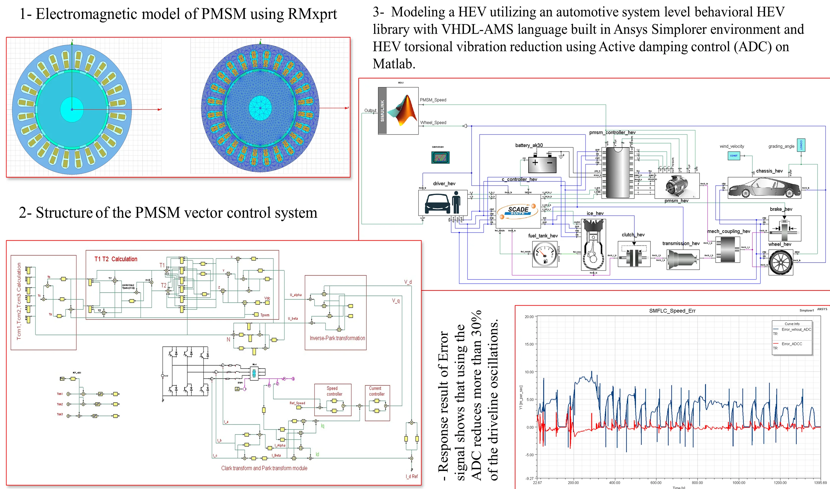
- Develop PMSM control system in Ansys after generating a Maxwell (2D) model of the motor by utilizing the RMxprt to construct the motor geometric model based on the motor's actual size and parameters for finite element analysis.
- Create the fundamental level modeling of a HEV powertrain based on VHDL-AMS language built in Ansys Simplorer and evaluates its performance throughout the certification driving cycle.
- Develop an Active damping control which is designed to control or reduce driveline oscillations in HEVs.
1. Introduction
Hybrid Electric Vehicle (HEV) and Electric Vehicle (EV) development has increased rapidly in recent years, because of a number of factors, including global warming, ever-increasing fuel costs, and heavy reliance on fossil fuels. The electrical powertrain is used in combination with the conventional powertrain to improve fuel efficiency and reduce emissions [1]. This approach, however, leads to an increased design complexity and expense. Therefore, computer models and simulations techniques are adapted to help reduce the design cost, time-consuming and optimize system performance. Modeling the dynamics of HEVs and their components is important because it allows researchers to better understand how the component will function, and also it enables designers to compare results with different parameters [2]. Simulation analysis is required to build a hybrid system with good performance and to enhance the powertrain configuration fast. The electric motor can be utilized to dampen powertrain speed fluctuations in a HEV application [3]. This is also known as active motor damping (AMD). In both conventional and hybrid powertrain applications, smooth driveline operation is one of the significant performance indicators [4] . Vehicle powertrain vibration or oscillations occur in almost all vehicles, whether non-hybrid or hybrid, which disrupt the smooth operation and drivability of the vehicle. In a conventional (non-hybrid) vehicle, since the driveline system components are elastic in nature, this leads to mechanical resonance [5]. When such a vehicle is exposed to disturbances, the elasticity nature of these components can cause driveline vibrations or disturbances, which can also generate driveline or vehicle oscillations [6]. However, the torque converter or clutch, together with the elastic nature of the driveline system in a conventional vehicle, offers a passive method of dampening vibrations and oscillations. An active damping control system is preferred to reduce the HEV’s driveline oscillations due to the lack of a passive damping mechanism (hardware) and owing to the reduce damping in HEVs [7].
Many studies have considered active vibration control algorithms in HEVs. B. Zhong et al. [8] proposes a novel longitudinal dynamic simulation model for a hybrid electric bus (series-parallel) with a module for active torsional vibration control. R. S. Vadamalu et al. [9] presents a model predictive controller (MPC) for active vibration reduction for a plug-in parallel HEV powertrain with a reduced 2-cylinder combustion engine. Variants in the time and frequency domains have been implemented. Drivetrain oscillations in a Motor-Transmission Integrated System (MTIS) caused by torque interruption for shifting are the main focus of this study [10]. Active vibration control is extremely difficult to implement in power-split HEVs due to the interaction of power sources and various vibration transfer paths. Active vibration control often employs dampening methods based on self-learning algorithms. This kind of control mechanism is very adaptable and is not affected by changes in the model's parameters. Wang developed a dual loop self-learning fuzzy control technique for automatic mechanical transmission gear engagement [11]. For uncertain systems having harmonic disturbances of unknown frequencies, Madonski [12] proposed a control technique based on the active disturbance rejection control framework. Active torsional vibration control highly depends on real-time system status information to estimate the phase and amplitude of the target position torque fluctuations. The real-time torsional angle, the mode-switching signal, and speed of each component with an active actuator may be used to reduce system torsional vibration by compensating the corresponding torque. Walker et al. [13] performed a comparison of conventional vehicles with HEVs, demonstrating how rapid motor response with PID algorithms can considerably minimize vibration during the shifting process. A comparison of conventional vehicles with HEVs, demonstrating how rapid motor response with PID algorithms can considerably minimize vibration during the shifting process. Yin Chengliang et al. [14] developed a robust controller using the mu-synthesis approach to decrease vehicle jerk when HEV mode transitions, and verified the proposed controller using a hardware-in-the-loop (HIL) simulation. J. Justin Wilbanks et al. [15] used a linear combination of time-varying and constant components in the motor output torque to compensate for the engine's nonlinear response, effectively minimizing vibration during engine restart. Modeling and simulation of HEVs with active vibration control were provided in the above publications, using different softwares to achieve good performance and accuracy.
This study focuses on the subject of powertrain oscillation by contributing a control method to improve HEVs driveline mechanical properties. we have considered a co-simulation based on Ansys and Matlab in order to solve the issue of controlling the powertrain oscillation. Torsional oscillations are a frequent yet annoying problems in the powertrain of electrically powered vehicles. However, the issue is more troublesome with electric motors than with internal combustion engines. Dampers do not seem to be essential, due to the smooth torque generated by electric motors. However, any unevenness in the driver's demand or, more precisely, in the load caused by road-wheel contact disturbances will induce mechanical resonances (at low powertrain oscillation frequency). Typically, the electric motor controller does not dampen the oscillations, since it is designed to generate the required torque regardless of the mechanical condition of the system. Vehicle powertrain oscillations are undesirable not just owing to the increased material stress, but also due to the reduced riding comfort caused by the oscillations, which may cause the whole vehicle to shudder very unpleasantly at low speeds. Corrective actions are required to increase riding comfort and reduce mechanical stress [8].
The general structure of this paper is as follows: Second section describes the HEV component modeling description. Section III focuses on the active motor damping controller design, which is based on the fuzzy logic and sliding mode controller. Section IV discusses the performance of the constructed controller, and section V presets the conclusions.
2. Hybrid electric vehicle modeling description
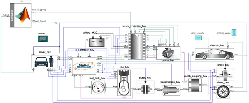
The hybrid electric vehicle (HEV) has both an engine and an electric motor that are configured to generate a vehicle powertrain torque. The torques produced by the engine and motor are combined via a mechanical coupler and delivered to the wheels [16]. The different components of the HEV with parallel architecture is shown in Fig. 1. Its major components of the powertrain model are divided into three categories: data/control components, electrical components and mechanical components.
Fig. 1Block diagram of HEV
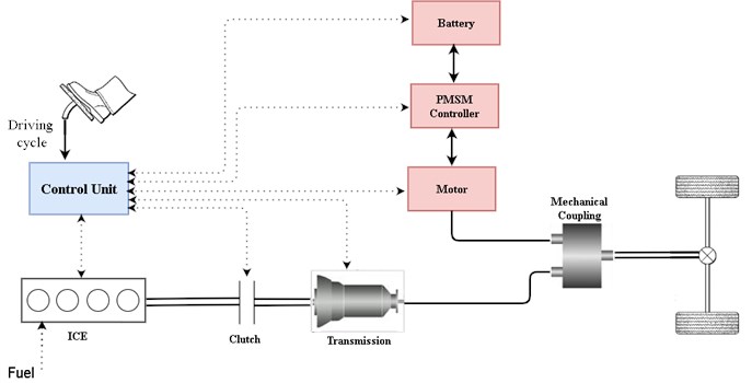
First is the Drive Cycle from the data/control components with the role of providing the appropriate vehicle speed by utilizing a 2D lookup table which uses a standard drive cycle data (FTP75 and NEDC). The driver model plays the velocity tracking behavior, which uses 2 PI controllers that generates a control signal to the powertrain input from the desired vehicle speed and actual speed. The driver also must indicate response signals for throttle, gear, and states (start, stop, and drive) to help other components controllers to adapt different behaviors in various stages. In this model, the driving functions as well as an equivalent energy management are integrated to determine the operation modes of the electric motor and Internal Combustion Engine (ICE). The central controller is the primary controller in charge of controlling the distribution of control signals. One of its functions is to determine the power distribution of the electrical and mechanical propulsion and braking systems. Based on the required torque and estimated rotational speed of the motor, the motor controller generates voltage and current for the Permanent Motor Synchronous Motor (PMSM). It also serves as a connection between the motor and battery.
Second is, the electrical components mostly comprise models for the electrical propulsion system (PMSM and battery model). The electrical motor model is integrated with the power electronics to produce the electric side torque from the power provided by the battery. When received a throttle signal, the available torque is scaled and current from the battery is requested. When in braking mode, the motor receives torque from the coupler torque and supplies power for charging to the battery. The user's input is the nominal power with the nominal rotating speed. The maximum torque is defined by this point. The nominal value also limits the maximum power. An electric model is used to calculate the current/voltage relationship as well as the state of charge of a battery (SOC). The equivalent circuit is made up of a voltage source that determines the open circuit voltage (OCV) as well as an internal resistance (R) that varies with SOC and current. Electric motor electromagnetic analysis is required to compute magnetic forces on stator teeth and also unbalanced forces on motor rotor. The magnetic analysis forces are used as input for harmonic and structural analysis. Because the analysis of an electric motor involves motion, it is necessary to use computation electromagnetics to do a time domain analysis. The studied PMSM machine is assumed to be running at 100 Hz, or 3000 rpm. The electrical excitation is a pure sinusoidal current waveform with peak current value of 200 A.
This analysis is based on a PMSM, which is 10-pole permanent magnet motor with 24 slots on the stator. Ansys Maxwell can be used to create a detailed 3D electromagnetics model for the motor that accounts for electromagnetic behavior, nonlinearity, and saturation. A complete 3D electromagnetic analysis is conducted to increase the accuracy of load transfer from electromagnetic to structural harmonic analysis. Additionally, it includes detailed information regarding the nonlinear effects of the motor (depending on its material properties and geometry). This modeling technique is capable of generating a precise and comprehensive description of an electrical motor. For advanced vehicle modeling, the Ansys software package offers an easy-to-use, dynamic, but robust and well-supported method to the vehicle engineering industry.
Fig. 2Vector control of PMSM
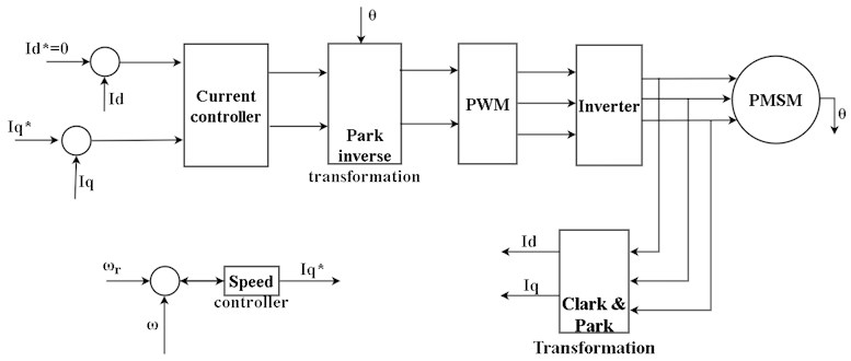
The PMSM controller, which uses vector control as shown in Fig. 2, determines the reference torque depending on the set speed. Simplorer models have been designed to enable optimizations considering integral performance criteria. The simulation model which contains two PI controllers (speed and current), and rotor position detection was developed using field-oriented vector control (FOC) [17]. The optimization procedure starts with the selection of initial values for controller parameters. So, when minimum error value is obtained, the optimization process will stop, and the optimal controller parameters are selected.
The amount of current needed to generate this torque is calculated by:
where is electromagnetic torque, is -axis current component, is a number of pole pairs and is permanent magnet flux amplitude.
The and axis components of the voltages are calculated by:
where and are d-axis and -axis equivalent inductances, is -axis current, which is adjusted to zero, and is stator winding resistance.
Third is the Mechanical components which includes the mechanical propulsion models and brake systems as well as the coupling/connection elements for electrical-mechanical combinations. It consists of the fuel tank, ICE, clutch, mechanical torque coupling, transmission, wheel, brake, and vehicle body (chassis). The ICE is the major power source for the drive train, and it is represented as a torque source with a maximum torque curve that is restricted by a throttle signal. The throttle body, the intake manifold, and the engine cylinder are the three main components of the ICE.
The internal combustion engine’s response characteristics can be modeled using a first order system with a time constant :
where is engine time constant; is engine output torque command.
The engine’s rotational components and associated clutch drive components can be described as a lumped moment of inertia. This lumped moment of inertia’s rotational speed is calculated by:
where lumped moment of inertia; is torque transmitted by clutch.
A first order system may be used to model the clutch actuator [18]. The normalized normal force is then obtained by:
where is the time constant of the clutch actuator, is normalized normal force command, and . A LuGre friction model can be used to model the clutch:
where denotes the bristle's average deflection, the clutch’s equivalent radius, the rotational speed of (lumped moment of inertia of the clutch's driving components). stiffness coefficient, is the Coulomb force, is the stiction force, the Stribeck velocity, and are the microscopic and macroscopic damping coefficient, respectively.
The clutch’s driving components, the motor’s rotor, and the transmission’s primary shaft may all be described as a lumped moment of inertia. The rotational speed of is given by:
where is motor torque, and the primary shaft's torque output.
A first order system can be used to represent the motor’s response characteristics. The motor output torque is determined by:
where motor time constant and is the motor output torque command.
Assuming that the driving axle shafts spin at the same speed, the final drive and differential may be described as a pair of gears. It’s possible to describe them as a lumped moment of inertia , and assuming that power is flow during mode transitions is from the hybrid power source to the drivetrain, we may calculate the rotational speed as follows:
where is final drive ratio, is final drive efficiency, and are torque from the secondary shaft and torque transmitted by axle shafts, respectively.
An equivalent elastic shaft can be used to model driving axle shafts, as follows:
where is axle shaft torsion, is rotational speed of wheel, is equivalent stiffness coefficient and is equivalent damping coefficient.
Assuming there is no slip between the road and the tires, the vehicle’s dynamics are represented as follows:
where is vehicle mass, is wheel radius, is the vehicle’s body and tires’ overall moment of inertia, is the external resistance torque, is road slope, is rolling resistance coefficient, is drag coefficient, is frontal area, is air density, and is vehicle longitudinal velocity.
VEHICLE DATA.
The vehicle has the following characteristics:
1) HEV modes:
–Braking mode.
–Traction mode.
2) Vehicle:
–Vehicle mass 1520 kg.
–Frontal projection area 1.70 m2, CD: 0.45.
–Wheel radius: 0.1905 m.
–Moment of inertia of wheel 2.0 kg-m2.
3) Electric machine (PMSM):
–Nominal power 60 kW at 2500 rpm.
4) Battery:
–20 cells (27.5 V, 11 Ahr @ SOC =1).
–4 series connection group for 5 parallel sets.
–110 V pack voltage.
5) ICE:
–Nominal power of 70 kW at 4500 rpm.
6) Transmission:
–Five-gear manual transmission.
–Gear ratios are (4.61, 3.03, 1.986, 1.42, 1.02).
7) Torque coupler:
–To ICE with a gear ratio of 2.0.
–To electric motor with a gear ratio of 2.5.
3. Active motor damping
The active control module for torsional vibration is added to the vehicle's original control system. The concepts of active damping control are based on destructive and superposition interference. This is accomplished by applying a force that is similar to the offending vibration but is in reverse phase with it [19]. When the vehicle is in motion, the driver takes the accelerator or brake pedals in accordance with the road conditions and the vehicle's condition. An instruction set is transmitted to each component actuator, along with the corresponding action, based on this input, as well as the information obtained by the vehicle control system. The development’s control system is primarily responsible for coordinating the internal combustion engine and electric motor [20], as well as maintaining a suitable level of charge in the hybrid battery pack and safeguarding the battery pack. Engine and electric motor coordination are dependent upon the driver's purpose, as expressed by the accelerator and braking pedals. Maintaining a proper level of charge is accomplished by regenerative braking or by utilizing the motor as a generator, drawing power from the engine. The battery pack is safeguarded by continuously monitoring factors such as current and temperature to ensure that manufacturer requirements are never exceeded.
The design of the damping controller must take into consideration a several objectives and limitations, including:
1) It is necessary to dampen vibrations.
2) The model has to be robust enough to take into account considerable input parameter variation and model uncertainty
3) Due to cost limitations, only existing measuring signals may be employed
3.1. Control architecture
The design purpose is to develop a fuzzy logic sliding mode controller by combining the fuzzy logic controller with its sliding mode control. Despite the fact that a fuzzy logic controller and a sliding mode controller are very similar, the combination of fuzzy logic control and sliding mode control has captivated researchers’ interest because the stability of a general fuzzy logic controller is difficult to prove, whereas the stability of a sliding mode controller is inherent. Additionally, combining fuzzy logic control with sliding mode control has the immediate advantage of efficiently reducing chattering, which is a major issue in sliding mode control systems. Sliding mode control (SMC) is a well-known control method for nonlinear uncertain systems that has been successfully applied to a broad range of application domains. SMC control strategy differs from other control methods in that the system structure is purposely modified in a dynamic process based on the system’s current state.
3.1.1. Sliding mode controller
During the design of SMC, the speed errors between the motor and the wheel speed is:
where is motor speed and is wheel speed.
Generally, there are three steps to design SMC: selecting the sliding-mode surface, designing the switching control law, and finally designing the sliding mode controller. Selecting the sliding surface as:
If moves towards zero, then and will similarly move towards zero. To ensure the sliding mode’s asymptotic stability, the design parameter (), that is the sliding line’s slope, is chosen so that ( 0). The time derivative of s can be given by:
Equivalent control law is found by setting Eq. (20) to 0:
where , , is the inertia constant and is the viscose fraction coefficient.
When designing a sliding mode controller, an equivalent control is first given such that each state of Lyapunov’s condition fulfilled for reaching the sliding surface:
Considering a Lyapunov function:
Stability condition can be defined as:
As such, inequality in Eq. (23) is referred to as the sliding surface’s reached condition.
The sliding mode Eq. (22) is achieved, in such a way that the controller output should be chosen as:
where is the switching function, is a positive constant, and is a sign function.
3.1.2. Fuzzy logic sliding controller
The controller output with sliding mode in Eq. (24) is written as equivalent control and compensate controller :
The suggested controller is separated into two parts; calculating the equivalent control in Eq. (21) and producing compensate control using fuzzy logic. The proposed controller takes into the error signal “”, which is the difference between the actual and the desired speeds, the change in the error signal “”, and output variable as the corrective control signal .
There are seven membership functions for the input variable and which are labeled: Negative Big NB, Negative Medium NM, Negative Small NS, Zero ZE, Positive Small PS, Positive Medium PM, and Positive Big PB. To satisfy the existence requirement, the control rules (as shown in table 1) must be designed in such a way the states' actual trajectory always turns toward and never crosses the sliding surface onto the phase plane.
Table 1Fuzzy function
, | NB | NM | NS | ZE | PS | PM | PB |
NB | NB | NB | NB | NB | NM | NS | ZE |
NM | NB | NB | NB | NM | NS | ZE | PS |
NS | NB | NB | NM | NS | ZE | PS | PM |
ZE | NB | NM | NS | ZE | PS | PM | PB |
PS | NM | NS | ZE | PS | PM | PB | PB |
PM | NS | ZE | PS | PM | PB | PB | PB |
PB | ZE | PS | PM | PB | PB | PB | PB |
Defuzzification
When the fuzzy controller outputs fuzzy sets, these fuzzy sets need to be converted into numerical values. Using the center of area method (COA) algorithm, defuzzification is performed in an efficient manner.
Fig. 3Sliding mode control and Fuzzy logic in Matlab
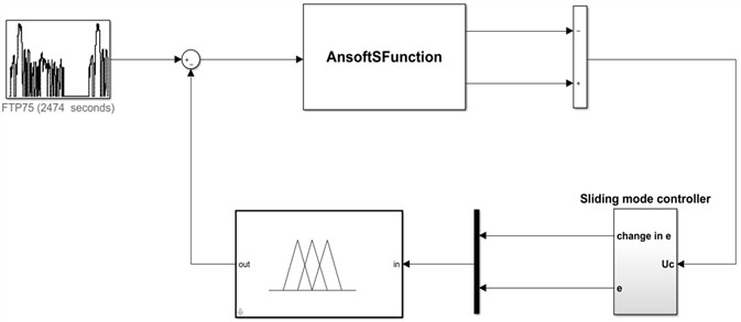
Fig. 4Complete simulation model
After developing the active damping control in Simulink, a continuous data exchange between these components is required to conduct the co-simulation (Matlab, Simplorer, and Maxwell models) [21], as seen in the complete model of Ansys and Simulink in Fig. 4. Such a simulation method will be advantageous for accurate detailed modeling and system optimization.
To begin, the Simulink–Simplorer co-simulation is accomplished by adding (linking to) a Simulink sub-circuit to the Simplorer circuit, where the simulation results are shown in the Simplorer graphical environment. Second, using the Sim2Sim link interface, Matlab’s S-Function (provided by the Ansys Software Manufacturer) is constructed in Simulink with the required name “AnsoftSFunction”.
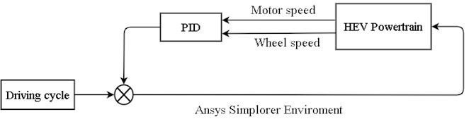
3.2. PID controller
Proportional-Integral-Derivative (PID) controllers have been used for process control in industries for a long time, and they're still used today. Each component of the hybrid electric vehicle was described in VHDL-AMS, including structural models. The resulting blocks were connected in the Simplorer 2019 Software environment in order to produce a high-level description of our system as shown in Fig. 5. PID tuning is accomplished by increasing the gain till the loop oscillates at a constant amplitude. (When an error correction's response is quick, a larger gain may be applied. If the response is slow, a gain of a small gain is desired). Then adjust the gain of the PID controller to half that number and the reset time to ensure that any offset is corrected within an acceptable period. Next, increase the rate of the PID loop till the overshoot is reduced.
Fig. 5PID controller in Simplorer Environment
4. Simulation result and discussion
This section presents the simulations results. Hence, the objective is to develop an appropriate control method for controlling oscillations or vibration of powertrain in HEVs by using active dampers. For the purpose of evaluating vehicle performance, the automotive industry and government agencies conduct regular tests known as standard drive cycles, based on which vehicle fuel economy certification is given. Standard drive cycles are designed in such a way that they include both a road grade as well as a speed component.
The dynamic driveline model for the Simplorer HEV was first simulated without the vibration-reduction control method. The vehicle's given reference velocity from standard driving cycle in comparison to the calculated vehicle velocity is shown in Fig. 6. The controller of the driver model receives the signal from the instantaneous difference between such velocities. The ICE generates the majority of the torque required for motion, particularly at higher speeds. At lower speeds, the electric motor is more often employed, taking use of the considerable torque available at such speeds. Because the ICE is inefficient at lower speeds, the hybrid arrangement saves gasoline.
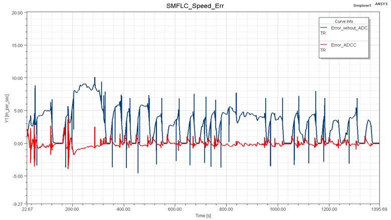
The system response is seen in Fig. 7 compares the simulation results obtained in Parallel-HEVs driving mode with and without ADC. It can be seen that when the ADC is activated, the peak to peak amplitude of the error signal is lowered and the axle torque fluctuation is minimized. Before the ADC, the error signal quickly changes from 7.46 to –3, after ADC the error signal peak to peak value lowered to less than 3 to –0.5. The peak to peak value with the proposed controller is reduced more than 30 % of the vehicle without the controller. The simulations showed that the proposed active damping control system improves drivability by lowering driveline oscillation peak to peak value to less than 3, which was previously more than 7.
Fig. 6HEV speed profile
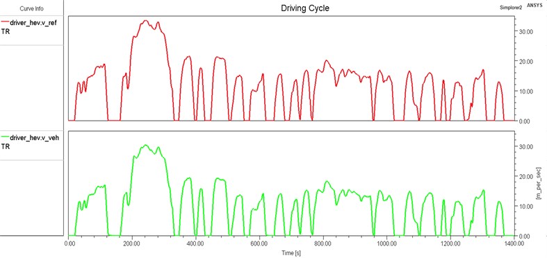
Fig. 7Response result of error signal
The torque values at the torque coupler are shown in Fig. 8 with the electric machine shaft first, the ICE second, and the axle to wheels shaft third. As can be seen, when no active control strategy is used, the torque fluctuates at mechanical coupler, resulting in torsional vibration in the system. After using an active control method, the torque fluctuation has been reduced by more than 40 % of that without the controller.
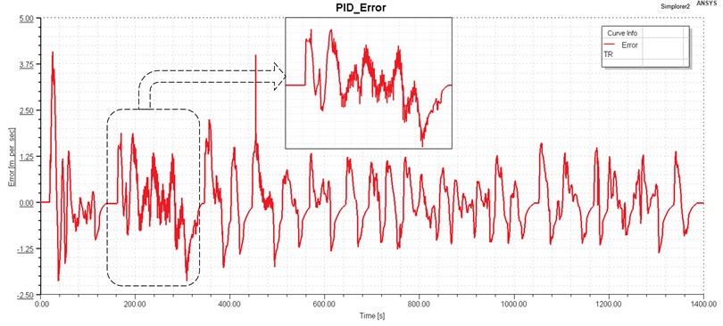
The performance of a well-tuned PID controller is clearly good in terms of system robustness and predictability, which is why they are often preferred for usage in industry. The proposed PID was verified by running the simulation for 1400 ms to get these results. The error signal peak to peak value ranged from 7.46 to –3 before the use of the PID controller, but after the development of the controller, the error signal peak to peak value decreased to less than 6.5 to –2 after the use of the controller as shown in the Fig. 9. There are, unfortunately, slight oscillations. Along the curves, the magnitude has decreased, leading to improved riding comfort. The peak to peak value of the proposed controller has shown a 10 % reduction error speed without the controller. As a conclusion, the HEV drivability can be slightly improved by employing the proposed PID controller.
Fig. 8Torque distribution with/without ADC
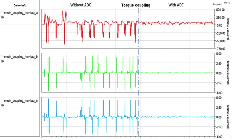
Fig. 9Speed error with PID controller
As can be seen when no active control strategy is used, the speed error (the difference between motor speed and wheel speed) fluctuates, resulting in torsional oscillation in the system. After implementing an active control technique, the torsional vibration of the drivetrain fluctuation can be properly reduced. In order to select the best control method that reduces the drivetrain oscillation, all methods were investigated with the same working condition, i.e. the same vehicle speed driving cycle and at the simulation time of 1400 ms. The fuzzy logic sliding controller has a lower peak to peak value and better performance in terms of speed error tracking compared to PID controller. It is important to note that the vibration amplitude has been significantly reduced. In addition, even though the PID control has been utilized, it can still show with an extra oscillation. Simulations showed that the proposed controller could dampen the oscillations in the driveline.
5. Conclusions
This paper has presented the parallel hybrid electric powertrain model based on VHDL-AMS language built in Ansys Simplorer software and the design of active damping controller using fuzzy logic sliding mode controller implemented in Matlab/Simulink and proportional-integral-derivative (PID) controller. The permanent magnet synchronous motor (PMSM) model for a hybrid electric vehicle (HEV) is developed using Ansoft software, and then finite element analysis and theory of electromagnetic fields are combined to enhance the accuracy of the modeling and minimize the simulation time. The contribution of the model is that the rigid-flexible coupling characteristics of the system are considered and the vibration characteristics of the system under instantaneous force excitation can be accurately simulated. The simulations were performed using the FTP75 drive cycle. The simulation results show that the hybrid power assembly can reflect the coupling of rigid body and flexible body of the system, and produce torque fluctuation and system vibration under external excitation, so as to meet the requirements of the subsequent active vibration control of the power system. Hence, the suggested controllers can reduce driveline oscillations and thereby improve the drivability of HEVs. The fuzzy logic sliding mode controller not only achieves more accurate control precision, but also has real-time control performance, which contributes a new practical method for active vibration reduction control of HEV drivetrain and better solves the problem of HEV powertrain oscillation. Further work is strongly suggested to enhance the performance of the PMSM for low speed and wide range dynamic applications as well as improve the active damping controllers to more than 70 % oscillation reduction. Also, a HEV implementation will be far more successful if we understand the industry’s requirements and constraints. Academia and industry must collaborate and communicate more closely in order to produce useful results that will be valuable to the automotive industry.
References
-
Y. Wei, Y. Wang, and Z. Hou, “Optimization on energy management strategy with vibration control for hybrid vehicles,” Vibration Engineering for a Sustainable Future, pp. 129–135, 2021, https://doi.org/10.1007/978-3-030-47618-2_16
-
X. Tang, W. Yang, X. Hu, and D. Zhang, “A novel simplified model for torsional vibration analysis of a series-parallel hybrid electric vehicle,” Mechanical Systems and Signal Processing, Vol. 85, pp. 329–338, Feb. 2017, https://doi.org/10.1016/j.ymssp.2016.08.020
-
K. Cakir and A. Šabanović, “In-wheel motor design for electric vehicles,” in 9th IEEE International Workshop on Advanced Motion Control, pp. 613–618, 2006.
-
E. Goudarzi, “Improving ride comfort using control systems design for active damper,” Sweden, Department of Mechanics and Maritime Sciences, 2019.
-
F. Syed, M. Kuang, and H. Ying, “Active damping wheel-torque control system to reduce driveline oscillations in a power-split hybrid electric vehicle,” IEEE Transactions on Vehicular Technology, Vol. 58, No. 9, pp. 4769–4785, 2009.
-
X. Zhang et al., “Modelling and active damping of engine torque ripple in a power-split hybrid electric vehicle,” Control Engineering Practice, Vol. 104, p. 104634, Nov. 2020, https://doi.org/10.1016/j.conengprac.2020.104634
-
H. Liu, X. Zhang, Y. Chen, M. Taha, and H. Xu, “Active damping of driveline vibration in power-split hybrid vehicles based on model reference control,” Control Engineering Practice, Vol. 91, p. 104085, Oct. 2019, https://doi.org/10.1016/j.conengprac.2019.07.003
-
B. Zhong, B. Deng, and H. Zhao, “Simulation model and method for active torsional vibration control of an HEV,” Applied Sciences, Vol. 9, No. 1, p. 34, Dec. 2018, https://doi.org/10.3390/app9010034
-
R. S. Vadamalu and C. Beidl, “MPC for active torsional vibration reduction of hybrid electric powertrains,” IFAC-PapersOnLine, Vol. 49, No. 11, pp. 756–761, 2016, https://doi.org/10.1016/j.ifacol.2016.08.110
-
C. Lin, S. Sun, P. Walker, and N. Zhang, “Off-line optimization based active control of torsional oscillation for electric vehicle drivetrain,” Applied Sciences, Vol. 7, No. 12, p. 1261, Dec. 2017, https://doi.org/10.3390/app7121261
-
X. Wang, L. Li, K. He, and C. Liu, “Dual-loop self-learning fuzzy control for AMT gear engagement: Design and experiment,” IEEE Transactions on Fuzzy Systems, Vol. 26, No. 4, pp. 1813–1822, 2017.
-
R. Madonski, M. Stanković, S. Shao, Z. Gao, J. Yang, and S. Li, “Active disturbance rejection control of torsional plant with unknown frequency harmonic disturbance,” Control Engineering Practice, Vol. 100, p. 104413, Jul. 2020, https://doi.org/10.1016/j.conengprac.2020.104413
-
P. D. Walker and N. Zhang, “Active damping of transient vibration in dual clutch transmission equipped powertrains: A comparison of conventional and hybrid electric vehicles,” Mechanism and Machine Theory, Vol. 77, pp. 1–12, Jul. 2014, https://doi.org/10.1016/j.mechmachtheory.2014.02.008
-
H. Zhang, Y. Zhang, and C. Yin, “Hardware-in-the-loop simulation of robust mode transition control for a series-parallel hybrid electric vehicle,” IEEE Transactions on Vehicular Technology, Vol. 65, No. 3, pp. 1059–1069, 2015.
-
J. Justin Wilbanks and M. Leamy, “Two-scale command shaping for reducing powertrain vibration during engine restart,” Journal of Dynamic Systems, Measurement, Vol. 139, No. 9, p. 09100, 2017.
-
M.-K. Tran, M. Akinsanya, S. Panchal, R. Fraser, and M. Fowler, “Design of a hybrid electric vehicle powertrain for performance optimization considering various powertrain components and configurations,” Vehicles, Vol. 3, No. 1, pp. 20–32, Dec. 2020, https://doi.org/10.3390/vehicles3010002
-
M. T. Kassa and D. Changqing, “Design optimization and simulation of PMSM based on Maxwell and TwinBuilder for EVs,” in 8th International Conference on Electrical and Electronics Engineering (ICEEE), pp. 99–103, 2021.
-
D. Guo, C. Du, and F. Yan, “Drivability-related discrete-time model predictive control of mode transition in pre-transmission parallel hybrid powertrains,” Energies, Vol. 9, No. 9, p. 740, Sep. 2016, https://doi.org/10.3390/en9090740
-
Gong Zuo and Li Wong, “A review on recent active vibration control techniques,” arXiv:1601.05889, 2016.
-
H.-Y. Hwang, T.-S. Lan, and J.-S. Chen, “Control strategy development of driveline vibration reduction for power-split hybrid vehicles,” Applied Sciences, Vol. 10, No. 5, p. 1712, Mar. 2020, https://doi.org/10.3390/app10051712
-
T. K. Mersha and C. Du, “Co-simulation and modeling of PMSM based on Ansys software and Simulink for EVs,” World Electric Vehicle Journal, Vol. 13, No. 1, Dec. 2021, https://doi.org/10.3390/wevj13010004
Cited by
About this article

This work was financially supported by the Natural Science Foundation of China (51775393), the 111 Project (B17034) and the Technology innovation plan of Hubei Province, China (2018AAA053).
