Abstract
The bolt joint is the key component connecting the rigid moving base body and the flexible manipulator. The dynamic characteristics of the flexible manipulator under the elastic constraint of the joint are analyzed, and the action mechanism of the elastic constraint of the bolt joint on the frequency and vibration mode is revealed. Considering the effects of line constraint and torsion constraint, the elastic constraint model of the joint is established. Based on the principle of virtual work, the boundary constraints of the joint end and the free end are established, and the analytical equation of frequency and the expression of vibration mode function are derived. The first three frequencies and vibration mode characteristics of the flexible manipulator under elastic constraints are analyzed numerically. The sensitivity method is used to analyze the effect of linear constraints and torsional constraints on the frequency, and the elastic constraint region is established to characterize the functional relationship between the binding stiffness and the natural frequency. It is found that under elastic constraints, the influence of torsional stiffness of bolt joint is mainly concentrated in the low-order modal frequency, while the linear stiffness has a great influence on each order modal frequency of the manipulator; With the decrease of elastic constraint stiffness, its influence on modal shapes gradually increases, especially on high-order modal shapes. The research results prove the internal mechanism of the influence of elastic constraints on vibration characteristics, which provide a theoretical basis for improving the dynamic characteristics of flexible manipulator.
Highlights
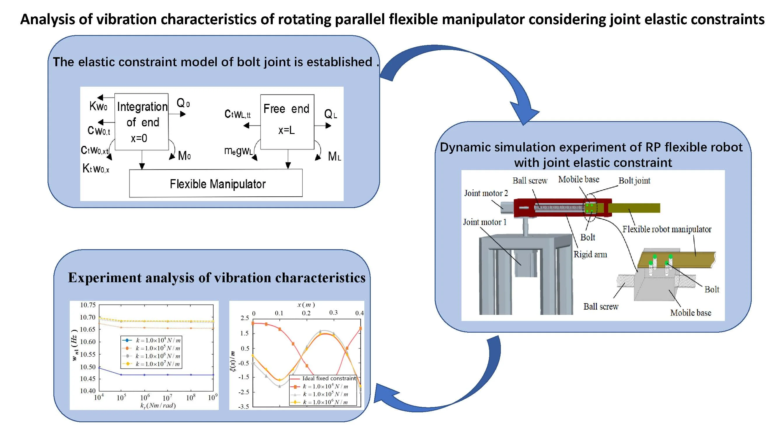
- The elastic constraint model of bolt joint is established
- Dynamic simulation experiment of RP flexible robot with joint elastic constraint
- Experiment analysis of vibration characteristics
1. Introduction
With the continuous development of modern manufacturing equipment in the direction of lightweight and integration, the traditional rigid manipulators are difficult to meet this requirement. As a typical flexible structure, compared with rigid structure, flexible manipulator has been widely used in the field of medical devices because of its light weight, flexible operation and low energy consumption [1]. Due to the movement of flexible manipulator, there are large-scale rigid motion and small displacement elastic vibration [2-4], and this elastic vibration will further affect the dynamic characteristics of the robot body through the bolt joint, thus seriously reducing the positioning accuracy and working efficiency of the end effector [5]. In the existing research on the dynamic characteristics of flexible manipulator, it is usually assumed that the joint has absolute connection stiffness and its constraint is regarded as complete rigidity. But in fact, the joint makes the mechanical structure discontinuous and nonlinear [6-9]. Moreover, the contact stiffness of the joint is the main component of the system stiffness, so it should not be simply regarded as a complete rigid constraint between parts. Therefore, the dynamic characteristics of the joint determine the dynamic characteristics of the whole machine structure to a certain extent [10, 11]. Therefore, in order to obtain better dynamic characteristics of the flexible manipulator, in-depth study of the influence mechanism of the constraint characteristics of the bolt joint on the dynamic characteristics of the manipulator has important engineering application value [12, 13].
Aiming at the dynamic characteristics of joint and flexible manipulator, scholars at home and abroad have made some research results. Dhupia [14] modeled the dynamics of the guide rail slider joint based on the spring equivalent theory, and analyzed the influence of the joint on the dynamic characteristics of the system structure by using the frequency response function. Kim [15] established the numerical model of the joint surface under different constraints based on the spring equivalent theory. Yang et al. [16] established the dynamic model of Euler Bernoulli beam in rotating state, which laid a foundation for further study of the dynamic characteristics of the system. Liu Yufei et al. [17] established elastic boundary constraints and carried out vibration modal analysis of complex cantilever beams, which provided a theoretical basis for the establishment of elastic constraint boundary conditions. Liu Yufei [18] studied the vibration response and power flow characteristics of flexible manipulator with moving base. Andreaus [19] studied the dynamics of friction vibrator on moving base under driving force excitation and obtained the important conclusion that the motion characteristics of rigid base have a significant impact on the vibration response and power flow of flexible manipulator with moving base. Zhao Jieliang et al. [20] used the modified response surface method to analyze the sensitivity of harmonic driving parameters of space flexible manipulator. Lu [21] comprehensively used genetic algorithm and sensitivity method to identify and optimize model parameters. Liu et al. [22] studied the dynamics and stability of bolted flexible Cartesian manipulator based on sensitivity and multi-scale method.
The above research results have conducted a more in-depth analysis on the dynamic characteristics of the joint and the flexible manipulator, but there are relatively few research results on the dynamic characteristics of the rigid and flexible coupled manipulators considering the elastic constraints of the joint. In particular, how to accurately characterize the constraint state of the elastic joint and analyze the dynamic characteristics of the flexible manipulator under the influence of the joint need to be deeply studied.
The elastic constraint model of bolt joint is established based on the global constraints of linear stiffness and torsional stiffness; According to the principle of virtual work, the boundary constraints of the joint end and the free end are defined, the frequency equation and mode shape function are deduced, and the action relationship of elastic constraints on frequency and mode shape is analyzed; The sensitivity method is used to analyze the influence of line constraint and torsional constraint on its frequency; The function model of constraint stiffness and frequency under elastic constraints is constructed, the action relationship of elastic constraints at the joint is characterized, and the internal mechanism of the influence of elastic constraints on the vibration characteristics of flexible manipulator is explored.
2. Elastic constraint model of joint and establishment of boundary conditions
RP (rotation parallel) flexible robot manipulator is mainly composed of a rotating joint and a moving joint. It has a large workspace and can realize large-scale rapid movement and accurate positioning. It is of great significance to further study it. According to the structural characteristics of RP flexible robot, the coupling structure between rigid moving base and flexible manipulator through bolts can be characterized as shown in Fig. 1.
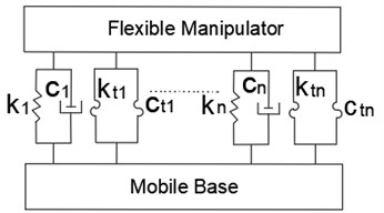
Considering the elastic constraint effect between bolt joints, multiple groups of linear springs and torsion springs are used to characterize them, and the elastic constraint model between flexible manipulator and moving base is established as shown in Fig. 2, where, (N/m) and (N⋅s/m) respectively represent line constraint stiffness and damping coefficient, (N⋅m/rad) and (N⋅s/rad) respectively represent torsional restraint stiffness and damping coefficient.
Fig. 1RP (rotation parallel) flexible robot manipulator
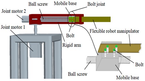
Fig. 2Elastic restraint model of the joints
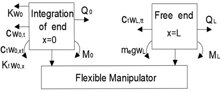
According to the established elastic constraint model of the joint, the stress analysis of the joint end and free end of the flexible manipulator is carried out, and the results are shown in Fig. 3. Where, and respectively represent the vibration displacement of the joint end ( 0) and the free end () of the flexible manipulator. and respectively represent the shear force and bending moment at the joint end of the flexible operating arm. and respectively represent the shear force and bending moment at the free end of the flexible manipulator. represents the gravity coefficient:
Fig. 3Force analysis of the flexible manipulator
According to the bending deformation characteristics of the flexible manipulator during movement, the shear and bending moment when the flexible manipulator is elastically deformed are:
where, is the elastic modulus of the flexible operating arm. is its moment of inertia, , and is the width and thickness of the rectangular section of the flexible manipulator respectively.
According to the stress analysis diagram of the joint end and free end of the flexible operating arm shown in Fig. 3, the shear force and bending moment of the joint end and free end of the operating arm are:
According to the virtual work principle, for a static balanced system, the sum of work done by all active forces acting on the virtual displacement of the action point is zero. Assuming that the virtual displacement of the system is , the total work done by the shear and bending moment at the joint end of the flexible manipulator ( 0) is 0, that is:
Similarly, the total work done by the shear force and bending moment at the free end of the flexible manipulator () is 0, that is:
Since the virtual displacement is an ideal instantaneous small displacement independent of time change, it is an arbitrary variable. Therefore, according to Eq. (5)-Eq. (6), the boundary conditions of the joint ( 0) end and free end () of the manipulator can be deduced as follows:
It can be seen from Eq. (7) that the boundary constraints at the joint end are related to the structural damping , of the system. However, since the system damping force generally exists in the case of relative motion speed, and the flexible operating arm is fixedly connected with the moving base through the bolt joint, there is no relative motion. Therefore, in order to facilitate the modal analysis, the influence of structural damping is ignored. So the boundary conditions at the joint end ( 0) of the flexible manipulator can be expressed as:
3. Dynamic characteristics analysis of flexible manipulator under elastic constraints of joint
3.1. Frequency equation and vibration mode function of flexible manipulator
Based on the hypothetical modal method, the vibration displacement of the flexible manipulator is expressed in the linear combination form of modal function as follows:
Then Eq. (8) and Eq. (9) can be further expressed as:
Using the undetermined coefficient method [23], the vibration mode function of the flexible manipulator under the elastic constraint of the joint is expressed as:
where, , , and are undetermined coefficient. is a variable related to angular frequency and satisfies the relationship .
According to Eq. (13), , , and can be written as follows:
Substitute Eq. (13) into Eq. (11) to obtain:
where, .
Similarly, substitute Eq. (13) into Eq. (12) to obtain:
where, .
Multiply Eq. (15) to the right , Eq. (16) left multiplication , after finishing will get:
The above formula is further expressed as follows:
where:
It can be seen from Eq. (13) that the coefficients , , and cannot all be zero. Then Eq. (18) shall satisfy the following relationship:
The above formula can be expanded, which can obtain the modal frequency equation of the flexible manipulator under the elastic constraint of the joint:
It can be obtained from Eq. (16):
Substituting Eq. (21) and Eq. (22) into Eq. (13), it can be obtained that the vibration mode function of the flexible manipulator under the elastic constraint of the joint is:
where .
It can be obtained from Eq. (18):
where , , , .
From Eq. (20) and Eq. (23), it can be seen that the modal frequency and mode shape function of the flexible manipulator are closely related to , the elastic constraint stiffness of the joint. In order to study the dynamic characteristics of the bolt part and ignore the end load , Eq. (20) and Eq. (23) are further transformed into:
where .
In order to verify the correctness of modal equation, it is assumed that the constraint condition is a idea constraint , , at this time, Eq. (25) and Eq. (26) are:
The above formula is the frequency equation and mode shape function of the flexible manipulator under the constraints of ideal (fixed free) boundary conditions. However, in practice, the linear stiffness and torsional stiffness close to infinity (, ) do not exist. Therefore, when analyzing the dynamic characteristics of flexible manipulator, if the bolt joint is regarded as an ideal fixed constraint and the elastic constraint is ignored, it will produce errors or even wrong conclusions to the analysis results.
3.2. Analysis of modal frequency characteristics of flexible manipulator under different elastic constraints of joint
The experimental system for modal frequency characteristic test is shown in Fig. 4.
The structural parameters of the flexible manipulator are shown in Table 1.
Since there is an approximate proportional relationship between the restraint stiffness of the bolt joint and the applied preload, the value range of the bolt restraint stiffness is 1.0×10⁴–1.0×10⁹, where the linear stiffness is taken as 1×10⁴ N/m, 1×10⁵ N/m, 1×10⁶ N/m and 1×10⁷ N/m respectively, and the torsional stiffness is rounded in the range 104-109, unit Nm/rad. The values under different constraint stiffness can be solved according to Eq. (25), and the results are shown in Table 2-Table 4.
Fig. 4The experimental system for modal frequency characteristic test
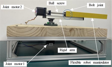
Table 1Structural parameters of flexible manipulator
Length (mm) | Width (mm) | Thickness (mm) | Modulus of elasticity | Density | Poisson’s ratio |
350 | 40 | 2 | 25.24 GPa | 2030kg/m3 | 0.26 |
Table 2First-order value of β with different restraint rigidities
𝑘 | ||||
1.0×10⁴ | 1.0×10⁵ | 1.0×10⁶ | 1.0×10⁷ | |
1.0×10⁴ | 4.6521 | 4.6783 | 4.6918 | 4.6918 |
1.0×10⁵ | 4.6390 | 4.6792 | 4.6883 | 4.6894 |
1.0×10⁶ | 4.6376 | 4.6790 | 4.6874 | 4.6812 |
1.0×10⁷ | 4.6376 | 4.6792 | 4.6874 | 4.6812 |
1.0×10⁸ | 4.6376 | 4.6792 | 4.6874 | 4.6812 |
1.0×10⁹ | 4.6376 | 4.6792 | 4.6874 | 4.6812 |
Table 3Second-order value of β with different restraint rigidities
𝑘 | ||||
1.0×10⁴ | 1.0×10⁵ | 1.0×10⁶ | 1.0×10⁷ | |
1.0×10⁴ | 10.2774 | 11.5917 | 11.7268 | 11.7342 |
1.0×10⁵ | 10.2716 | 11.5837 | 11.7217 | 11.7321 |
1.0×10⁶ | 10.2736 | 11.5842 | 11.7205 | 11.7334 |
1.0×10⁷ | 10.2736 | 11.5841 | 11.7205 | 11.7334 |
1.0×10⁸ | 10.2736 | 11.5841 | 11.7205 | 11.7334 |
1.0×10⁹ | 10.2736 | 11.5841 | 11.7205 | 11.7334 |
Table 4Third-order value of β with different restraint rigidities
𝑘 | ||||
1.0×10⁴ | 1.0×10⁵ | 1.0×10⁶ | 1.0×10⁷ | |
1.0×10⁴ | 15.2237 | 18.8738 | 19.5873 | 19.6577 |
1.0×10⁵ | 15.2232 | 18.8719 | 19.8741 | 19.6428 |
1.0×10⁶ | 15.2232 | 18.8752 | 19.5693 | 19.6409 |
1.0×10⁷ | 15.2232 | 18.8752 | 19.5679 | 19.6409 |
1.0×10⁸ | 15.2232 | 18.8752 | 19.5679 | 19.6409 |
1.0×10⁹ | 15.2232 | 18.8752 | 19.5679 | 19.6409 |
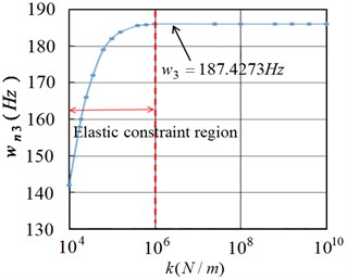
The angular frequency of the flexible manipulator under different elastic constraints can be obtained by substituting the obtained value of into the Eq. (12). For the natural frequency and angular frequency of the flexible manipulator, due to . The natural frequency characteristic diagram of the flexible manipulator under different elastic constraints can be solved based on Ansys, and the first three natural frequency characteristic diagrams can be extracted, as shown in Fig. 5-Fig. 7. Without considering the elastic constraint, according to Eq. (27) and Eq. (12), the first three natural frequencies of the flexible manipulator under the constraint conditions can be calculated respectively as 10.6801 Hz, 66.9317 Hz and 187.4121 Hz.
Fig. 5First natural frequency of the flexible manipulator
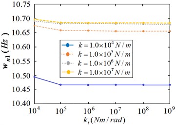
Fig. 6Second natural frequency of the flexible manipulator
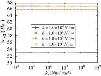
Fig. 7Third natural frequency of the flexible manipulator
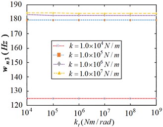
Fig. 5 shows the first natural frequency of the flexible manipulator considering the joint under different elastic constraints. It can be seen from the Fig. 5 that the linear stiffness tends to be stable when the torsional stiffness 1.0×10⁵ Nm/rad. With the increase of linear stiffness , the natural frequency of the flexible manipulator gradually increases from 10.4537 Hz, 10.6530 Hz, 10.6781 Hz to 10.6801 Hz. Moreover, when the linear stiffness is 1.0×10⁶ N/m, and with the increases of , the first-order natural frequency of the flexible manipulator changes little, about 10.6801 Hz. As shown in Fig. 6 and Fig. 7, the second-order and third-order natural frequency characteristics are shown respectively. It can be seen from the Fig. 7 that with the increase of torsional stiffness, the change degree of the second-order and third-order natural frequencies is significantly lower than that of the first-order natural frequency, and the change of the natural frequency value of each order is small. When the linear stiffness is 1.0×10⁶ N/m, and with the increases of , the second-order and third-order natural frequencies of the flexible manipulator respectively gradually tend to be stable, which are 66.9317 Hz and 187.4121 Hz.
From the above characteristic curves, we can draw the following conclusions: the linear stiffness of the bolt joint under elastic constraints has a significant impact on each order modal frequency of the flexible manipulator, while the impact of torsional stiffness is mainly concentrated in the low order modal frequency.
3.3. Modal frequency sensitivity analysis of flexible manipulator under different elastic constraints
In order to further explore the influence of linear stiffness and torsional stiffness on the natural frequency of flexible manipulator, sensitivity analysis needs to be carried out. The frequency sensitivity function is defined according to the frequency Eq. (25):
Then the sensitivity expressions of linear stiffness and torsional stiffness are:
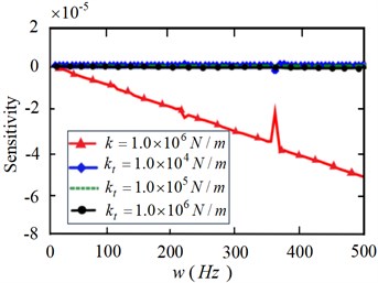
According to the above formula, take the linear stiffness 1.0×10⁴ N/m, 1.0×10⁵ N/m, 1.0×10⁶ N/m, torsional stiffness 1.0×10⁴ Nm/rad, 1.0×10⁵ Nm/rad, 1.0×10⁶ Nm/rad and conduct numerical simulation based on ANSYS and the sensitivity curves between natural frequency and linear stiffness and between natural frequency and torsional stiffness. As shown in Fig. 8-Fig. 9.
Fig. 8Sensitivity of natural frequencies to the restraint stiffness K
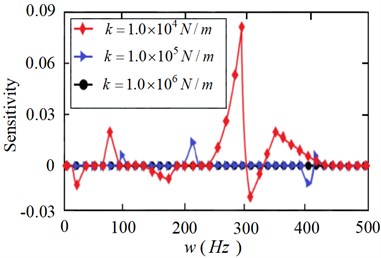
Fig. 9Sensitivity of natural frequencies to the restraint stiffness kt
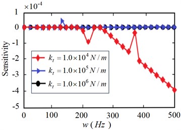
As can be seen from Fig. 8, when the linear stiffness is 1.0×10⁴ N/m, the sensitivity to the natural frequency of the flexible manipulator is the largest. With the gradual increase of linear stiffness , its sensitivity to natural frequency gradually decreases, especially in the high frequency band. As can be seen from Fig. 9, when the torsional stiffness is 1.0×10⁴ Nm/rad, the sensitivity to the natural frequency of the flexible manipulator shows a downward trend. When the torsional stiffness 1.0×10⁵ Nm/rad, 1.0×10⁶ Nm/rad, its sensitivity to natural frequency tends to be stable.
Fig. 8 and Fig. 9 generally show that the sensitivity of frequency to linear stiffness is greater than that of torsional stiffness ; Fig. 10 further shows the specific comparison of the sensitivity of modal frequency to linear stiffnessand torsional stiffness under the elastic constraint of the joint. It can be seen from the Fig. 10 that the frequency sensitivity under the elastic constraint of the joint decreases gradually with the increase of the linear stiffness , and the change of torsional stiffness has little effect on the sensitivity, but it also shows that when the torsional stiffness is low, its effect on the modal frequency is also obvious. In conclusion, under the elastic constraint state of the joint, the sensitivity of the linear stiffness to the modal frequency of the flexible manipulator is higher than the torsional stiffness , which shows that the linear stiffness has a greater impact on the modal frequency.
Fig. 10Comparative analysis of modal frequency sensitivity of manipulator
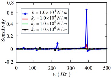
a)
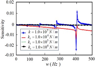
b)
c)
3.4. Modal analysis of flexible manipulator under different elastic constraints
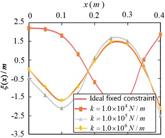
According to the modal shape function Eq. (25) of the flexible manipulator, the first three modal shapes are analyzed based on ANSYS and the analysis results are shown in the Fig. 11-13.
It can be seen from Fig. 10 that the first-order modal shape under the elastic constraint of the joint presents a parabola trend with the opening downward, and when the constraint stiffness decreases from 1.0×10⁶ N/m to 1.0×10⁴ N/m, the modal shape curve deviates from the ideal constraint more and more. It can be seen from Fig. 12-Fig. 13 that second-order and third-order vibration modes of the flexible manipulator under elastic constraints and those under ideal constraints not only show strong nonlinear characteristics, but also show great differences. When the stiffness constrained is 1.0×10⁴ N/m, the third-order mode shape curve shows a sinusoidal variation trend with opposite amplitude. It can be seen that the elastic constraint of the joint has a great influence on the vibration mode characteristics of the flexible manipulator, and the greater the difference between the vibration mode characteristic curve and the ideal constraint with the decrease of the elastic constraint stiffness.
Fig. 11First order modal shapes of flexible manipulator
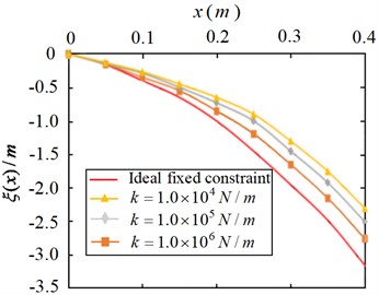
Fig. 12Second order modal shapes of flexible manipulator
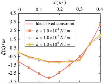
Fig. 13Third order modal shapes of flexible manipulator
3.5. Elastic constraint numerical model of joint
According to the modal characteristics and sensitivity analysis of the flexible manipulator, the elastic constraint of the joint of the manipulator is mainly linear constraint. Therefore, when the torsional stiffness , the elastic restraint effect of the joint can be expressed by the linear stiffness. Then, Eq. (25) and Eq. (26) are further expressed as:
where .
In order to further explore the relationship between the elastic constraint area of the joint and the modal frequency of the flexible manipulator, the relationship curve between the linear stiffness of the joint and the first three natural frequencies of the flexible manipulator is obtained based on ANSYS. As are shown in Fig. 14-Fig. 16.
From Fig. 14 to Fig. 16, it can be seen that 1.0×10⁴-1.0×10⁶ is the elastic constraint area of the joint, and with the increase of linear stiffness, the natural frequency of the flexible operating arm gradually increases and approaches the frequency value under ideal constraint conditions (10.6801 Hz, 66.9317 Hz, 187.4121 Hz).
In order to further explore the action mechanism between constraint stiffness and natural frequency in the elastic constraint area, and according to the power function relationship characteristics shown in Fig. 13-Fig. 15, an approximate function is constructed as follows:
Fig. 14Relation curve between tension constraint stiffness and first-order modal frequency
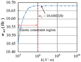
Fig. 15Relation curve between tension constraint stiffness and second-order modal frequency
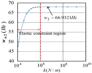
Fig. 16Relation curve between tension constraint stiffness and third-order modal frequency
According to the sample data and fitting the curve based on Matlab, the relationship function curves between the joint elastic constraint and the flexible manipulator under the first, second and third modes are obtained respectively, as shown in Fig. 17-Fig. 19.
Fig. 17Fitting curve of first-order modal frequency of flexible manipulator
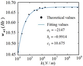
Fig. 18Fitting curve of second-order modal frequency of flexible manipulator
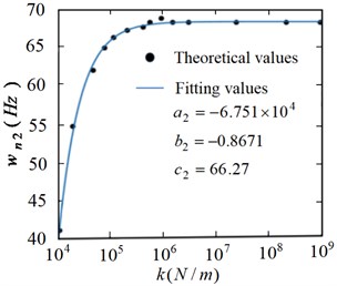
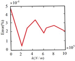
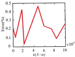
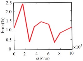
From Fig. 17 to Fig. 19, it can be seen that the frequency value obtained from the frequency fitting equation is consistent with the result obtained from the numerical solution. That is, the actual value basically coincides with the relationship function curve. In order to further illustrate the effectiveness of fitting with power function, Fig. 20 shows the error analysis of the solution results of the fitting equation.
It can be seen that the fitting degree of the first-order frequency is high, the fitting errors of the second-order and third-order are less than 0.5 % and 2.5 % respectively, and the fitting error decreases gradually with the increase of constraint stiffness. This shows that the constructed numerical function is effective and can accurately characterize the relationship between the constraint stiffness and frequency of the joint under elastic constraints, which provides a theoretical basis for the in-depth study of the dynamic characteristics of the flexible manipulator under the elastic constraints of the bolt joint.
Fig. 19Fitting curve of third-order modal frequency of flexible manipulator
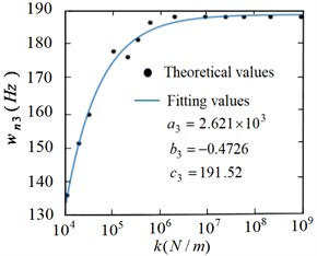
Fig. 20Frequency fitting error analysis of flexible manipulator
a) First order
b) Second order
c) Third order
4. Conclusions
Taking the bolt joint between the robot flexible manipulator and the steel body as the research object, the influence law of the elastic constraint of the joint on the dynamic characteristics of the flexible manipulator is analyzed based on ANSYS, the influence mechanism is revealed, and the following conclusions are obtained:
Considering the effects of line constraint and torsion constraint, the elastic constraint model of the joint is established. Based on the virtual work principle, the boundary constraints of the joint end and the free end are defined, and the analytical equation of modal frequency and the expression of modal function are derived.
1) Based on the numerical analysis method, the action mechanism of elastic constraints on the first three modal frequencies and modal shape characteristics of flexible manipulator is explored. The influence degree of linear constraint and torsional constraint on frequency is analyzed by sensitivity method, the elastic constraint region is established, and the relationship function expression between constraint stiffness and natural frequency is constructed.
2) It is found that under elastic constraints, the linear stiffness of the bolt joint has a great influence on each order mode of the manipulator, and the influence of torsional stiffness is mainly concentrated in the low order mode. Compared with torsional stiffness, linear stiffness has a greater influence on frequency.
The research results prove the internal influence mechanism of elastic constraints on vibration characteristics, and provide a theoretical basis for improving the dynamic characteristics of flexible manipulator.
References
-
H. N. Rahimi and M. Nazemizadeh, “Dynamic analysis and intelligent control techniques for flexible manipulators: A review,” Advanced Robotics, Vol. 28, No. 2, pp. 63–76, Jan. 2014, https://doi.org/10.1080/01691864.2013.839079
-
S. Nima Mahmoodi and M. Ahmadian, “Modified acceleration feedback for active vibration control of aerospace structures,” Smart Materials and Structures, Vol. 19, No. 6, p. 065015, Jun. 2010, https://doi.org/10.1088/0964-1726/19/6/065015
-
J. Han, B. Zhang, and R. Ma, “Adaptive fuzzy control of nonlinear aeroelastic system with measurement noise,” Journal of Vibroengineering, Vol. 23, No. 5, pp. 1184–1195, Aug. 2021, https://doi.org/10.21595/jve.2021.21738
-
S. Abiko and K. Yoshida, “Adaptive reaction control for space robotic applications with dynamic model uncertainty,” Advanced Robotics, Vol. 24, No. 8-9, pp. 1099–1126, Jan. 2010, https://doi.org/10.1163/016918610x501264
-
T. Guo, L. Li, L. Cai, and Y. Zhao, “Alternative method for identification of the dynamic properties of bolted joints,” Journal of Mechanical Science and Technology, Vol. 26, No. 10, pp. 3017–3027, Oct. 2012, https://doi.org/10.1007/s12206-012-0815-7
-
Y. Zhao, C. Yang, L. Cai, W. Shi, and Z. Liu, “Surface contact stress-based nonlinear virtual material method for dynamic analysis of bolted joint of machine tool,” Precision Engineering, Vol. 43, pp. 230–240, Jan. 2016, https://doi.org/10.1016/j.precisioneng.2015.08.002
-
R. Wang, L. Zhu, and C. Zhu, “Research on fractal model of normal contact stiffness for mechanical joint considering asperity interaction,” International Journal of Mechanical Sciences, Vol. 134, pp. 357–369, Dec. 2017, https://doi.org/10.1016/j.ijmecsci.2017.10.019
-
B. Pratiher and S. K. Dwivedy, “Non-linear dynamics of a flexible single link Cartesian manipulator,” International Journal of Non-Linear Mechanics, Vol. 42, No. 9, pp. 1062–1073, Nov. 2007, https://doi.org/10.1016/j.ijnonlinmec.2007.06.001
-
K. Zhu and J. Chung, “Nonlinear lateral vibrations of a deploying Euler-Bernoulli beam with a spinning motion,” International Journal of Mechanical Sciences, Vol. 90, pp. 200–212, Jan. 2015, https://doi.org/10.1016/j.ijmecsci.2014.11.009
-
A. Molter, O. A. A. Da Silveira, J. S. O. Fonseca, and V. Bottega, “Simultaneous piezoelectric actuator and sensor placement optimization and control design of manipulators with flexible links using SDRE method,” Mathematical Problems in Engineering, Vol. 2010, pp. 1–23, 2010, https://doi.org/10.1155/2010/362437
-
M.-X. Lin, S.-Y. Lee, and C.O.-K. Chen, “Dynamic characteristic analysis of an electrostatically-actuated circular nanoplate subject to surface effects,” Applied Mathematical Modelling, Vol. 63, pp. 18–31, Nov. 2018, https://doi.org/10.1016/j.apm.2018.06.004
-
M. Latour, V. Piluso, and G. Rizzano, “Cyclic modeling of bolted beam-to-column connections: Component approach,” Journal of Earthquake Engineering, Vol. 15, No. 4, pp. 537–563, Apr. 2011, https://doi.org/10.1080/13632469.2010.513423
-
B. Mandal and A. Chakrabarti, “A simple homogenization scheme for 3D finite element analysis of composite bolted joints,” Composite Structures, Vol. 120, pp. 1–9, Feb. 2015, https://doi.org/10.1016/j.compstruct.2014.09.061
-
J. S. Dhupia, B. Powalka, A. G. Ulsoy, and R. Katz, “Effect of a nonlinear joint on the dynamic performance of a machine tool,” Journal of Manufacturing Science and Engineering, Vol. 129, No. 5, pp. 943–950, Oct. 2007, https://doi.org/10.1115/1.2752830
-
S.-M. Kim, J.-H. Ha, S.-H. Jeong, and S.-K. Lee, “Effect of joint conditions on the dynamic behavior of a grinding wheel spindle,” International Journal of Machine Tools and Manufacture, Vol. 41, No. 12, pp. 1749–1761, Sep. 2001, https://doi.org/10.1016/s0890-6955(01)00040-2
-
J. B. Yang, L. J. Jiang, and D. C. Chen, “Dynamic modelling and control of a rotating Euler-Bernoulli beam,” Journal of Sound and Vibration, Vol. 274, No. 3-5, pp. 863–875, Jul. 2004, https://doi.org/10.1016/s0022-460x(03)00611-4
-
Y.-F. Liu, W. Li, and X.-F. Yang, “Vibration modal analysis of cantilever beams with complicated elasticity boundary constraint,” Sixth International Conference on Nonlinear Mechanics (ICNM-VI), pp. 197–200, 2013.
-
Y. Liu, W. Li, X. Yang, M. Fan, Y. Wang, and E. Lu, “Vibration response and power flow characteristics of a flexible manipulator with a moving base,” Shock and Vibration, Vol. 2015, pp. 1–8, 2015, https://doi.org/10.1155/2015/589507
-
U. Andreaus and P. Casini, “Dynamics of friction oscillators excited by a moving base and/or driving force,” Journal of Sound and Vibration, Vol. 245, No. 4, pp. 685–699, Aug. 2001, https://doi.org/10.1006/jsvi.2000.3555
-
J. Zhao, S. Yan, and J. Wu, “Analysis of parameter sensitivity of space manipulator with harmonic drive based on the revised response surface method,” Acta Astronautica, Vol. 98, No. 1, pp. 86–96, May 2014, https://doi.org/10.1016/j.actaastro.2014.01.017
-
Y. Lu and Z. Tu, “Dynamic model updating using a combined genetic-eigensensitivity algorithm and application in seismic response prediction,” Earthquake Engineering and Structural Dynamics, Vol. 34, No. 9, pp. 1149–1170, Jul. 2005, https://doi.org/10.1002/eqe.472
-
Y. Liu, W. Li, X. Yang, and Y. Wang, “Dynamic and stability of harmonic driving flexible cartesian robotic arm with bolted joints based on the sensitivity and multiple scales method,” Mathematical Problems in Engineering, Vol. 2015, pp. 1–12, 2015, https://doi.org/10.1155/2015/795101
-
K. Wei, W. Zhang, P. Xia, and Y. Liu, “Nonlinear dynamics of an electrorheological sandwich beam with rotary oscillation,” Journal of Applied Mathematics, Vol. 2012, pp. 1–17, 2012, https://doi.org/10.1155/2012/659872
Cited by
About this article

This work was supported by the National Natural Science Foundation of China (61772247), Key projects of Natural Science Foundation of Zhejiang Province (LZ21F020003), the National Natural Science Foundation of Zhejiang Province (LY20E050002, LY18F030001) and Nanjing Xiaozhuang College Talent Fund (2020 NXY14).
