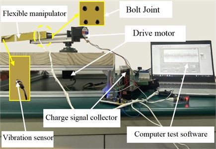
Abstract
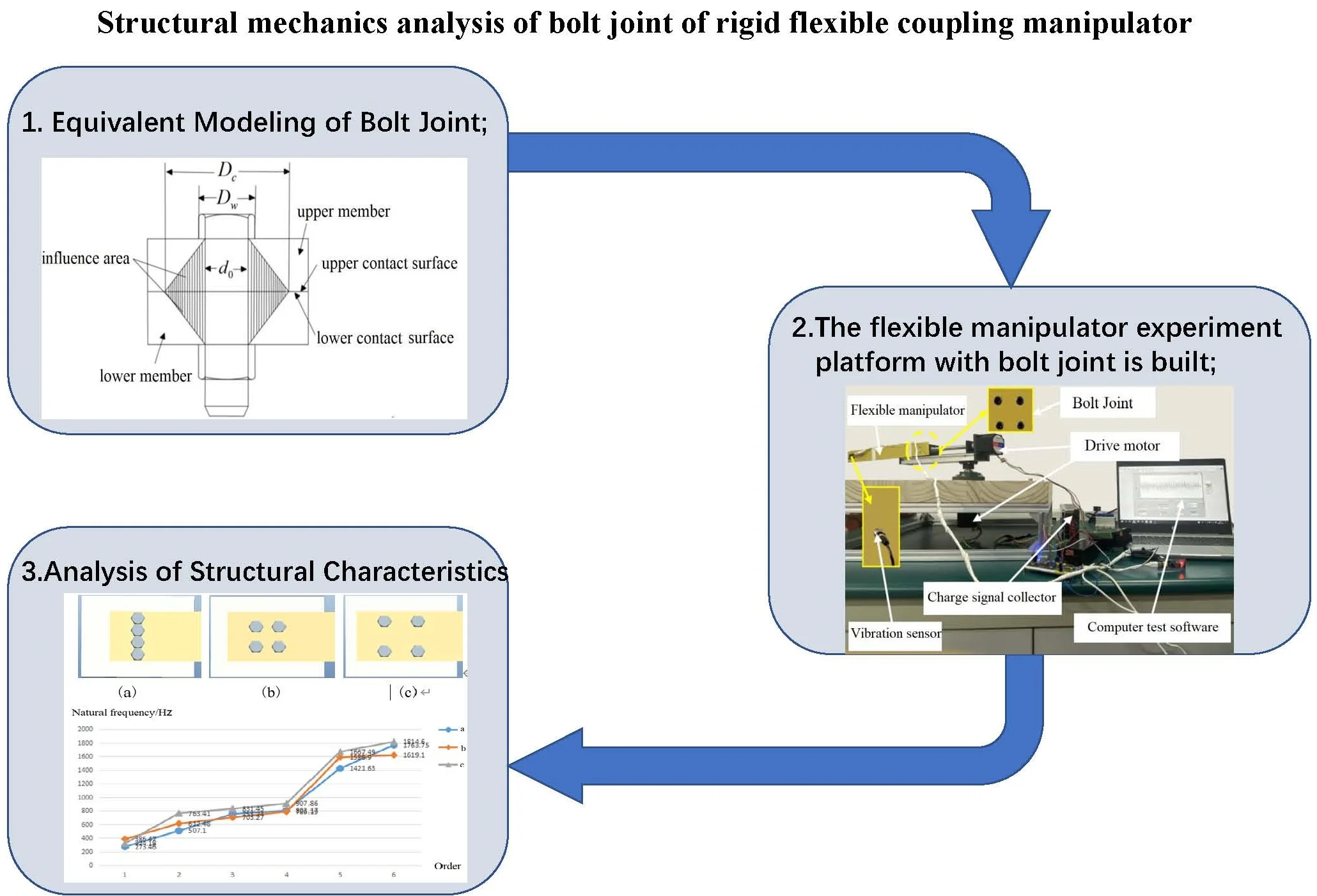
As the key connecting part of the rigid flexible coupling manipulator, the structural dynamic characteristics of the bolted joint are analyzed by using the joint simulation technology of pro/e and ANSYS. Based on the spring equivalent principle, the finite element equivalent model of bolt joint is established, the relationship equation between contact surface pressure and bolt preload is derived, and its stress state is analyzed; Based on the micro convex deformation model and Hertz contact theory, the tangential stiffness equation and normal stiffness equation of the bolted joint are derived respectively. The three-dimensional model of the bolted joint is established by using pro/e and imported into ANSYS for joint simulation. The simulation experiments reveal the influence of bolt joint vibration characteristics under different conditions from the aspects of bolt diameter, pre tightening force, bolt group number and bolt distribution. The conclusions have important engineering value for the structural optimization of rigid flexible coupling manipulator.
Highlights
- Equivalent Modeling of Bolt Joint
- The flexible manipulator experiment platform with bolt joint is built
- Analysis of Structural Characteristics of Bolt Joint based on ANSYS
1. Introduction
Due to the advantages of light weight, fast speed and low energy consumption, flexible manipulator has gradually attracted the attention of industry and academia [1, 2]. At present, the flexible manipulator represented by RP (rotary parallel) rigid flexible manipulator is gradually applied to the field of medical devices. The manipulator is mainly composed of a flexible manipulator whose rotating rigid arm is connected to the end through a moving base. Large workspace, large-scale rapid movement and precise positioning can be achieved. It is of great significance to study it in depth. However, the RP rigid flexible manipulator has large-scale rigid motion and small displacement elastic vibration [4, 5], which will further affect the dynamic characteristics of the robot rigid arm through the bolt joint, and then seriously reduce the positioning accuracy and work efficiency of the end effector [6].
According to the structural characteristics of RP type flexible robot, the flexible operating arm is connected with the moving base through the bolt joint. In the actual movement process, the mechanical vibration will be transmitted to the flexible operating arm through the bolt joint, which will have a certain impact on the positioning accuracy of the end effector [7]. The change of the frequency and vibration mode characteristics of the bolt joint will cause the change of the vibration characteristics of the flexible manipulator. Therefore, the research on the structural vibration characteristics of the bolt joint will lay a foundation for the follow-up study on the vibration characteristics of the flexible manipulator. Bolted connections are widely used in mechanical structures because of their strong reliability and easy disassembly. In the whole mechanical system, 60 %-80 % of the structural stiffness and more than 90 % of the structural damping come from joints [9]. Bolted connections are coupled by a variety of complex joint surfaces, which makes bolted connections incompatible and nonlinear. Therefore, as one of the main forms of fixed connection between components, the complex dynamic characteristics of the bolt joint will have a great impact on the structural characteristics of the mechanical system [8], and become the main source of the error of the whole mechanical system. However, due to the complex physical characteristics of the bolt joint surface, the traditional finite element method can not directly model and analyze it. Therefore, it is of great significance to study a modeling method that can accurately reflect the joint characteristics.
Since the joint surfaces of the joint parts in contact with each other form a closed structure, and the joint surfaces are composed of countless discontinuous micro convex bodies, domestic and foreign scholars reveal the structural characteristics of the bolt joint from many aspects [10]. In 1966, Greenwood et al. [11] proposed GW model according to the contact form between rough surfaces, which opened up a new idea for solving such problems. Li et al. [12] established the plastic deformation model of the contact area between rigid ellipsoid and half plane. Domestic scholars You J. M. et al. [13] further considered the continuous transformation between elastic, elastic-plastic and complete plastic deformation of micro convex bodies, and proposed a statistical model suitable for rough contact characterization. Yoshimura et al. [14] proposed the spring damping element model of the equivalent joint. Li Y. S. et al. [15] established the spring damping element model of single bolt joint according to the principle of stiffness equivalence, and verified the rationality of the model through experiments. Hui et al. [16] conducted equivalent modeling of bolt joint based on virtual material layer method, and calculated the elastic modulus and Poisson’s ratio of virtual material according to the basic characteristic parameters. Zhang X. L. et al. [17] used a layer of isotropic virtual material as the equivalent model of the joint to study the different characteristics of the joint in the normal and tangential directions. Williams et al. [18] used the spring element model to analyze the relationship between the deformation of the joint and the preload of the bolt under external load.
Based on the above research, the modeling method of the bolt joint and the influencing factors of the dynamic characteristics are further studied and analyzed. Based on the joint simulation technology of pro/e and ANSYS, the structural characteristics of the bolt joint of the flexible manipulator are revealed. The main technical contributions of the proposed scheme are summarized below.
(1) The stress state of the bolted joint is analyzed, the relationship between the contact surface pressure of the joint surface and the bolt preload is established, and the equivalent model of the bolted joint is established based on the spring equivalent principle.
(2) Different from the traditional numerical mechanics calculation, based on the micro convex deformation model and Hertz contact theory, the tangential and normal stiffness equations of bolted connections are derived respectively, and the joint simulation model of pro/e and ANSYS is established.
(3) The influence of different joint conditions on the vibration characteristics of bolt joint is studied from the aspects of bolt diameter, pre tightening force, number of bolt groups and bolt distribution mode, and its structural characteristics are revealed.
2. Equivalent modeling of bolt joint
2.1. Stress analysis of bolt joint
The bolt joint is affected by the pre-tightening force and pre-tightening torque during operation, as shown in Fig. 1 [19, 20].
Fig. 1Stress diagram of bolt structure
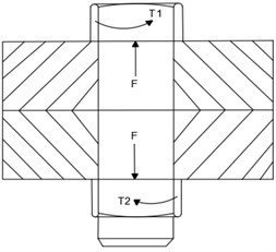
The bolt pre-tightening torque is composed of the friction torque between the nut and the member surface and the friction resistance torque between the screw pair, as shown in Eq. (1):
where is the friction coefficient of the nut (when there is no lubrication, ); is bolt preload; is the equivalent friction radius of the nut, is the outer diameter of the nut, is the nominal diameter of the thread, ; is the diameter of bolt hole, . is the pitch diameter of the thread, , is the rising angle of the thread, is the equivalent friction angle of the screw pair, and .
By combining Eq. (1)-(4), the approximate relationship between bolt preload and preload torque can be obtained as follows:
The relationship between the contact surface pressure of the joint surface and the bolt preload can be expressed as:
where represents the area of the joint surface.
2.2. Equivalent modeling of bolt joint
The stress distribution cloud diagram of the bolt joint is analyzed based on the finite element method (Fig. 2). When the bolt of the connecting member is subjected to the preload, the uneven contact surface pressure is distributed in a certain area around the bolt hole and decreases with the distance away from the center, which shows that the influence of the contact surface pressure of the bolt joint is local.
Considering the regional locality of the bolt influence area, the model diagram of the bolt influence area is given as shown in Fig. 3.
As shown in Fig. 3, the upper and lower members are fixedly connected by a bolt with diameter and bolt head diameter . As can be seen from Fig. 3, the pressure influence area of the contact surface of the bolt presents a truncated cone distribution as a whole, and then the pressure stress in the influence area presents a nonlinear distribution.
According to the spring equivalent theory proposed by Yoshimura et al. [15], the diameter of the equivalent pressure circle is used to characterize the range of the pressure influence area of the bolt contact surface. The diameter of the equivalent pressure circle can be expressed by the diameter when the contact pressure of the joint surface is zero. The equivalent model of the designed bolt joint is shown in Fig. 4.
Fig. 2Cloud diagram of stress distribution at bolt joint
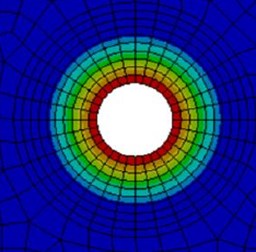
Fig. 3Bolt influence area model
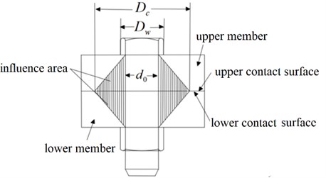
Fig. 4Spring element model

Fig. 5Equivalent element structure of spring damper
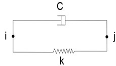
As shown in Fig. 4, each group of spring units includes 4 sets of normal holes and 4 sets of spring units. For each spring element, the unit module composed of spring damper is used for equivalent calculation, as shown in Fig. 5.
The structure can be compressed or stretched along the axis. It includes and nodes, and each node has three degrees of freedom in , and directions.
3. Stiffness characteristic equation of bolt joint
3.1. Normal stiffness equation of joint
In order to facilitate the analysis of the relationship between the normal load and the normal stiffness of the joint, the following assumptions are made:
1. The interface is the contact between rigid smooth surface and rough surface;
2. The normal load on the joint surface has the same effect on all parts of the joint surface.
Fig. 6 shows the model diagram of contact deformation between a single elastic micro convex body and a rigid plane. It can be seen from the Fig. 6 that when the additional load is applied to the joint surface, the micro convex body will deform and the normal stiffness will be generated between the joint surfaces.
The rough surface is equivalent to multiple micro convex bodies, and the equivalent radius of curvature of a single micro convex body is ; the deformation of the top is ; the contact radius is ; the normal load is . According to Hertz contact theory, the relationship between the normal load of a single micro convex body and the top deformation is as follows:
where is the equivalent elastic modulus between micro convex bodies, and . Where and are the elastic modulus of the two bonding materials, and are Poisson’s ratio of the two bonding materials.
Fig. 6Normal deformation model of micro convex body
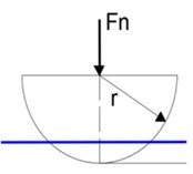
a) Before deformation
b) After deformation
According to the definition of normal stiffness, the normal stiffness of a single micro convex body can be obtained by deriving the top deformation in Eq. (6):
By introducing Eq. (9) into Eq. (8), the relationship between the normal stiffness of the micro convex body and the normal load is as follows:
Multiply and divide the normal load in Eq. (10) by the contact area of the micro convex body (where ) at the same time, the calculation result of the formula will not change, but the functional relationship expression between the normal stiffness and the contact surface pressure is obtained:
Considering that the area of the micro convex body is much smaller than the area of the contact surface, the normal stiffness of a single micro convex body is equivalent to the normal stiffness of the contact body per unit area, and Eq. (11) is simplified to the following exponential relationship:
where and are the normal foundation characteristic coefficient of the joint surface on the unit area.
3.2. Tangential stiffness equation of joint
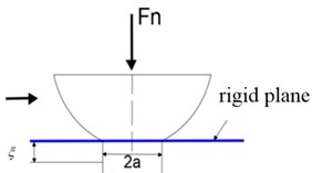
In the actual working condition, the joint is not only affected by the normal load , but also by the tangential load . When the contact micro convex body is subjected to tangential load, the micro convex body will undergo tangential deformation, as shown in Fig. 7.
Fig. 7Tangential deformation model of micro convex body
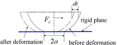
The expression of tangential deformation on a single elastic micro convex body is:
where is the static friction coefficient; is the equivalent tangential modulus when two rough surfaces are in contact. and are the tangential modulus of the two rough surfaces, and and are the Poisson’s ratio of the two rough surfaces.
Eq. (13) can be written in the following equivalent form:
According to the definition of tangential stiffness and Eq. (15), the expression of tangential stiffness of a single elastic micro convex body can be obtained as follows:
Square both sides of Eq. (15) at the same time to obtain the following formula:
Multiply and divide the normal load in Eq. (17) by the contact area of the micro convex body (where ) at the same time. The calculation result of the formula will not change, but the functional relationship expression between the tangential stiffness and the contact surface pressure is obtained:
Considering that the area of the micro convex body is much smaller than the area of the contact surface, the normal stiffness of a single micro convex body is equivalent to the normal stiffness of the contact body per unit area, and Eq. (18) is simplified to the following exponential relationship:
where and are the tangential foundation characteristic coefficient of the joint surface per unit area.
Then, the total normal stiffness and tangential stiffness of the joint surface are:
where represents the contact area of the joint surface, and the unit is m2.
4. Analysis of structural characteristics of bolt joint based on ANSYS
The flexible arm is made of epoxy resin sheet, with a surface roughness of 0, dimension value is 300 mm×100 mm×6 mm. The sliding block base is made of 45#steel with a surface roughness of 0 8um. Dimension value is 150 mm×150 mm×100 mm. According to the experimental data provided by reference [21], the basic characteristic coefficient of the joint surface per unit area is 3.262540, 0.604, 0.268894, 0.48. The sliding seat is connected with the flexible arm through bolts. The built flexible manipulator experiment platform with bolt joint is shown in the Fig. 8.
Fig. 8Tangential deformation model of micro convex body
Due to the strong nonlinearity, complex processing methods and diversified service conditions of the bolt joint [3, 22], the influencing factors of the dynamic characteristics of the bolt joint are diverse. Therefore, it is necessary to analyze the influence mechanism of the dynamic characteristics of the joint from the aspects of bolt preload, model, and quantity group and distribution mode.
4.1. Analysis of mechanical properties of bolt joint
4.1.1. Mechanical properties of bolt joint under different preloads
The bolts are applied with 20 N.m, 30 N.m, 40 N.m, 50 N.m, and the free modal analysis is carried out according to the established spring element model.
The pre-tightening torque of the bolt is transformed into the contact surface pressure of the joint surface through Eqs. (4) and (5), and then the normal stiffness and tangential stiffness of the joint surface under different pre-tightening torques can be obtained by using Eq. (12) and (19), as shown in Table 1.
Table 1Joint stiffness under different pre-tightening torques
Pre-tightening torque (N.m) | Normal stiffness (N/m) | Tangential stiffness (N/m) |
20 | 1.94×10¹⁰ | 1.28×10⁹ |
30 | 2.11×10¹⁰ | 1.42×10⁹ |
40 | 2.38×10¹⁰ | 1.59×10⁹ |
50 | 2.52×10¹⁰ | 1.71×10⁹ |
Based on the workbench environment of ANSYS, the cloud diagram of contact pressure distribution on the joint surface under different preloads is obtained (Fig. 9).
Fig. 9Cloud diagram of contact pressure distribution with different preload moments
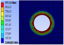
a) 20 N.m
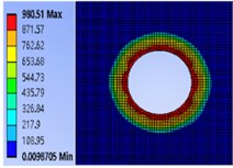
b) 30 N.m
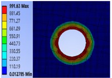
c) 40 N.m
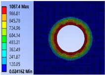
d) 50 N.m
It can be seen from Fig. 8 that the contact pressure of the contact surface of the bolt joint is mainly concentrated in a certain area around the bolt hole under different pre-tightening torques. Moreover, the closer to the edge of the hole, the greater the contact pressure, and the contact pressure away from the edge of the hole gradually decreases. At the same time, when the bolt pre-tightening torque is from 20 N.m gradually increases to 50 N.m. In the process of , the maximum contact pressure increases from 971.12 MPa, 980.51 MPa and 991.63 MPa to 1087.4 MPa, indicating that increasing the pre-tightening torque of the bolt will increase the pressure on the bolt contact surface.
4.1.2. Mechanical properties of different types of bolt joints
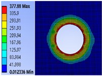
In order to explore the influence mechanism of bolt model on the contact pressure of joint surface of connector, several commonly used bolts of M6, M8, M10 and M12 are selected to study the influence law of bolt model on the contact pressure of joint surface. First, determine the pre-tightening torque of the bolt 40 N.m. Using the finite element method, the pressure distribution cloud diagram of the contact surface of the bolt connection part is obtained based on ANSYS (Fig. 10).
It can be seen from Fig. 10 that under the same pre-tightening torque, when the bolt diameter increases from M6 to M12, the maximum pressure values are 980.51 MPa, 721.02 MPa, 455.37 MPa and 377.88 MPa respectively, indicating that increasing the bolt diameter will gradually reduce the pressure on the contact surface.
Fig. 10Cloud diagram of contact surface pressure of different bolt models
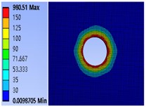
a) M6
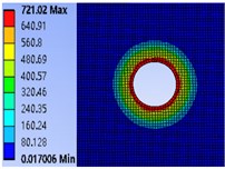
b) M8
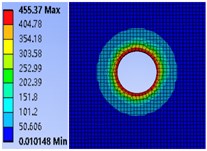
c) M10
d) M12
4.2. Modal frequency characteristics analysis of bolt joint
4.2.1. Modal frequency characteristics of joint under different number of bolts
The contact pressure of the joint surface is also different with the number of bolts. It is necessary to explore the influence mechanism of the number of bolts on the dynamic characteristics of the joint.
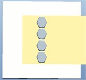
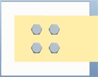
Based on Pro/E, the joint model under different bolt quantities is established (Fig. 11). In order to ensure the same contact pressure of the joint surface, the total preload torque of each method is set to be 40 N.m.
Fig. 11Different number of bolt models in a single arrangement
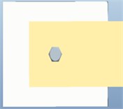
a)
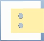
b)
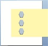
c)
d)
Substituting the above parameters into Eqs. (4), (5), (12) and (19), the normal stiffness of the joint surface is 2.38×10¹² N/m and the tangential stiffness is 2.66×10¹¹ N/m.
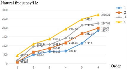
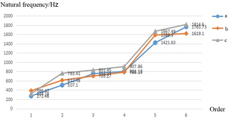
The stiffness of the bolt joint is equivalent to that of the spring element, and the finite element dynamic model of the bolt joint is established by using the combin14 element to equivalent the bolt joint. The spring stiffness is given to the combin14 element in the ANSYS element library in the form of real constant, and the finite element free modal analysis is carried out to extract the first six modal parameters, view the solution results in the results summary and extract the natural frequency solution results. The first six natural frequencies of different bolt numbers are obtained, as shown in Fig. 12.
As can be seen from Fig. 12, when the bolt pre-tightening torque is the same, the natural frequency of the joint increases gradually with the increase of the number of bolt connections. This is because under the action of the same bolt pre-tightening torque, the number of micro convex bodies in contact between the joint parts gradually increases, and the ability of the structure to resist deformation is enhanced, resulting in the increase of the stiffness of the joint part and the corresponding increase of the natural frequency of the joint part. Therefore, the arrangement of Fig. 11(d) is better.
Fig. 12Relationship between the number of bolts and natural frequency
4.2.2. Modal frequency characteristics of joint under different bolt distribution
In order to analyze the influence mechanism of different distribution modes of the same bolt number group on the dynamic characteristics of the joint. Similarly, by substituting the above parameters into Eqs. (4), (5), (12) and (19), the normal stiffness of the joint surface is 2.38×10¹⁰ N/m and the tangential stiffness is 1.59×10⁹ N/m.
Similarly, the stiffness of the bolt joint is equivalent to that of the spring element, and the finite element dynamic model of the bolt joint is established by using the combin14 element to equivalent the bolt joint. The spring stiffness is given to the combin14 element in the ANSYS element library in the form of real constant, and the finite element free modal analysis is carried out to extract the first six modal parameters. The first six natural frequencies of different distribution modes are obtained, as shown in Fig. 13.
Fig. 13Distribution of three bolt models

a)
b)
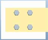
c)
It can be seen from Fig. 14 that when the bolt pre-tightening torque is the same, the distribution mode of the same number of bolts in Fig. 13(c) can obtain higher natural frequency. Therefore, better dynamic characteristics can be obtained by using decentralized equidistant arrangement.
Fig. 14Relationship between distribution mode and natural frequency
5. Conclusions
Based on the joint simulation technology of pro/e and ANSYS, the structural characteristics of the bolt joint of the flexible manipulator are revealed. The relationship equation between the contact surface pressure of the joint surface and the bolt preload is established, and the equivalent model of the bolt joint is established. The tangential stiffness equation and normal stiffness equation of bolted connection are derived, and the joint simulation model of pro/e and ANSYS is established. The simulation experiment reveals its structural characteristics from different aspects such as bolt diameter, pre tightening force, number of bolt groups and bolt distribution mode. (1) The greater the preload applied to the bolt, the greater the contact strength of the joint surface, and the greater the natural frequency of the bolt joint, resulting in an increase in the frequency of the flexible operating arm. (2) For the connection structure with the same material characteristics, the more bolts are connected, the greater the pressure on the contact surface between the connection surfaces, and the greater the natural frequency of the flexible manipulator. (3) When the number of bolts is the same, the arrangement of bolt groups is different, the stress forms of components are different, and the natural frequencies of flexible manipulator are also different. Increasing the bolt diameter can reduce the pressure on the contact surface, thus reducing the occurrence of stress concentration.
References
-
Yuanzhong Lei, “Research progress and prospect of mechanical engineering in China,” Journal of Mechanical Engineering, Vol. 45, No. 5, pp. 1–11, 2009.
-
H. Rahimi and M. Nazemizadeh, “Dynamic analysis and intelligent control techniques for flexible manipulators: a review,” Advanced Robotics, Vol. 28, No. 2, pp. 63–76, 2014.
-
S. K. Dwivedy and P. Eberhard, “Dynamic analysis of flexible manipulators, a literature review,” Mechanism and Machine Theory, Vol. 41, No. 7, pp. 749–777, Jul. 2006, https://doi.org/10.1016/j.mechmachtheory.2006.01.014
-
S. N. Mahmoodi and M. Ahmadian, “Modified acceleration feedback for active vibration control of aerospace structures,” Smart Materials and Structures, Vol. 19, No. 6, p. 065015, 2010.
-
S. Abiko and K. Yoshida, “Adaptive reaction control for space robotic applications with dynamic model uncertainty,” Advanced Robotics, Vol. 24, No. 8-9, pp. 1099–1126, Jan. 2010, https://doi.org/10.1163/016918610x501264
-
X. Zhang, H. Liu, and W. Cao, “Active control of elastic vibration of flexible mechanism,” Journal of Mechanical Engineering, Vol. 32, No. 1, pp. 9–16, 1996.
-
L. Gaul and R. Nitsche, “The role of friction in mechanical joints,” Applied Mechanics Reviews, Vol. 54, pp. 93–106, 2001.
-
S. Jiang and S. Zhu, “Dynamic stiffness characteristics of linear guide rail joint with ball screw pair,” Journal of Mechanical Engineering, Vol. 46, No. 1, pp. 92–99, 2010.
-
G. P. Zhang, Y. M. Huang, W. H. Shi, and W. P. Fu, “Predicting dynamic behaviours of a whole machine tool structure based on computer-aided engineering,” International Journal of Machine Tools and Manufacture, Vol. 43, No. 7, pp. 699–706, May 2003, https://doi.org/10.1016/s0890-6955(03)00026-9
-
J. A. Greenwood and J. B. P. Williamson, “Contact of nominally flat surfaces,” in Proceedings of the Royal Society of London A:Mathematical, Physical and Engneeing Sciences, 1966.
-
L. Li, I. Etsion, A. Ovcharenko, and F. E. Talke, “The onset of plastic yielding in a spherical shell compressed by a rigid flat,” Journal of Applied Mechanics, Vol. 78, No. 1, pp. 1–26, Jan. 2011, https://doi.org/10.1115/1.4001994
-
P. Y. Li et al., “Elasto-plastic analysis of the contact region between a rigid ellipsoid and a semi-flat surface,” Advances in Mechanical Engineeing, Vol. 10, No. 9, pp. 168–178, 2018.
-
You Jinmin and Chen Tianyu, “Study on statistical model of static contact parameters of joint surface,” Vibration and Shock, Vol. 29, No. 11, pp. 47–50, 2010.
-
M. Yoshimura, “Making use of CAD technology based on the dynamic characteristics data of joints to improve the structural rigidity of machine tools,” Machine Tools, Vol. 1, No. 1, pp. 142–146, 1979.
-
Y. Li et al., “A four point equivalent method of bolt joint stiffness,” Mechanical Strength, Vol. 3, pp. 153–157, 2017.
-
H. Ye, Y. Huang, P. Li, Y. Li, and L. Bai, “Virtual material parameter acquisition based on the basic characteristics of the bolt joint interfaces,” Tribology International, Vol. 95, pp. 109–117, Mar. 2016, https://doi.org/10.1016/j.triboint.2015.11.013
-
X. Zhang et al., “Modeling method of fixed joint based on equivalent transversely isotropic virtual material,” Journal of Mechanical Engineering, Vol. 15, pp. 141–147, 2017.
-
Williams J. G. et al., “Analysis of externally loaded bolted joints: analytical, computational and experimental,” International Journal of Pressure Vessels and Piping, Vol. 86, No. 7, pp. 420–427, 2008.
-
M. Iranzad and H. Ahmadian, “Identification of nonlinear bolted lap joint models,” Computers and Structures, Vol. 96-97, pp. 1–8, Apr. 2012, https://doi.org/10.1016/j.compstruc.2012.01.011
-
J. Zhang and Z. Tong, “Dynamic modeling of fixed joint surface of machine tool,” Vibration and Shock, Vol. 3, pp. 15–22, 1994.
-
X. Zhang, “Dynamic characteristics and application of mechanical joint,” China Science and Technology Press, Beijing, 2002.
-
Kerem Gurses, B. Buckham, and E. Park, “Vibration control of a single-link flexible manipulator using an array of fiber optic curvature sensors and PZT actuators,” Vibration Control of a Single-link Flexible Manipulator Using an Array of Fiber Optic Curvature Sensors and PZT Actuators, Vol. 19, No. 2, pp. 167–177, 2009.
Cited by
About this article

This work was supported by the National Natural Science Foundation of China (61772247), Key projects of Natural Science Foundation of Zhejiang Province (LZ21F020003), the National Natural Science Foundation of Zhejiang Province (LY20E050002, LY18F030001) and Nanjing Xiaozhuang College Talent Fund (2020 NXY14).
