Abstract
A hybrid intelligent control technique based on combination of neural network and fuzzy logic will be proposed for hydraulic actuated active suspension system. A half car model will be used for design of Adaptive Neuro Fuzzy Inference System (ANFIS) controller for hydraulic actuated active suspension. The nonlinear behavior of hydraulic system and uncertain parameters in active suspension has increased the difficulty of creating mathematical model for active suspension system. The performance of most of the classical controller depends on nature of mathematical model of system. Hence it is very difficult to create classical controller without mathematical model of a system. Fuzzy logic controller has ability to predict the behavior of system without the need of mathematical model of a system. In this paper, ANFIS controller proposed for active suspension due to its ability to handle actuator dynamics and parameter uncertainty in hydraulic actuator. The simulation carried out for sinusoidal road profile in order to measure the performance of proposed controller. The result of simulation indicates performance of the ANFIS controller for active suspension with actuator dynamics.
1. Introduction
A suspension system is a mechanism which consist of spring and damping element connected between wheel and car body. The suspension plays an important role to control the vertical dynamics of car body. The performance and characteristics of suspension system mainly depends on ride comfort and stability control of vehicle [1]. A better ride comfort can be achieved by using soft suspension, whereas better stability can be achieved with the help of hard suspension. The design of suspension involves optimization process where the elements are selected between soft and hard suspension. A suspension is normally classified into passive suspension, semi-active suspension and active suspension. Nowadays, lot of research works are going on [2-5] active suspension system because of its ability to operate wide range of frequency and forces. The performance of active suspension system obtained by measuring suspension travel and acceleration of vehicle body. Due to the development of microcontroller and computers [6-8], the real time implementation of active suspension can be done more effectively. The effect of ride comfort on suspension can be measured with the help of body acceleration of vehicle. Similarly, the performance of stability can be measured with the help of suspension travel.
An active suspension consists of spring, mass, damper and linear actuator which can be controlled with the help of on board sensor and controller. The nonlinear behaviour of hydraulic system and uncertain parameters in active suspension has increased the difficulty of creating mathematical model for active suspension system. A lot of investigation carried out by various researchers to design a controller for active suspension system. The performance of most of the classical controller depends on nature of mathematical model of system. Hence, the development of classical controller without mathematical model would be difficult for active suspension. The mathematical model of hydraulic actuator is difficult to create due to its complexity and unpredictable behaviour [9-13].
Alleyne and Hedrick developed a nonlinear controller based on sliding mode theory to handle hydraulic actuator dynamics in active suspension system [14]. The result of simulation indicates active suspension improves the performance of suspension better than passive suspension. Hrovat [15] addressed optimal controller for active suspension system using half car and full car model. He also discussed some issues in mathematical model of system. Williams [16] developed quatratic regulator controlled active suspension system using quarter car model.
Fuzzy logic has been employed in the field of active suspension in order to overcome the issues in mathematical model of active suspension. Fuzzy controller has ability to predict the behaviour of system without any mathematical model of a system. Rao and Prahlad [17] introduced fuzzy controller for active suspension using quarter car model where suspension travel and its derivative act as input to fuzzy controller. D’Amato and Viassolo [18] proposed a method to reduce vertical acceleration as well as vertical body displacement using fuzzy logic. Huang and Lin [19] developed adaptive fuzzy sliding controller where sliding function act as input and chattering effect can be eliminated using fuzzy controller at control output.
The rest of paper is arranged as follow. The mathematical model of half car model and its governing equation derived in Section 2. Section 3 explain the design of adaptive neuro fuzzy controller for half car model. The simulation and its result described in Section 4 and the conclusion in Section 5.
2. Modeling of suspension system
2.1. Mathematical modeling
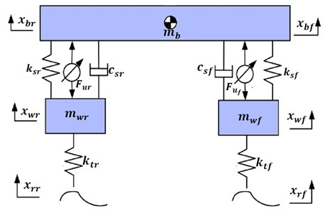
The half car model of suspension system including actuator dynamics can be modeled as shown in Fig. 1. The mass of the vehicle represented by symbol . The front and rear mass of wheel indicated by , . The stiffness and damping of front suspension namely , placed between front wheel and body. Similarly, stiffness and damping of rear suspension namely , placed between rear wheel and body. Hydraulic system will be used to generate front and rear actuator force through hydraulic servo valve. and are the vertical displacements of the car body at front and rear corner respectively. and indicates vertical displacement of front and rear wheel. Table 1 lists the parameters of the hydraulic actuated active suspension system.
Fig. 1Half car suspension model
2.2. System description
The dynamics for the suspension system, including the actuator and when the suspension travel is below its physical limit, is described by the linear Eqs. (1-4):
The actuator force developed by hydraulic actuator is described by the nonlinear Eqs. (5-6):
where , , and . is the conversion gain, and represent servo valve voltage [20]. Where indicate the body acceleration about C.G; , refers to the front and rear wheel acceleration; , refers to actuator force in front and rear wheel. Four-way valve-piston system is used for modeling of hydraulic actuator [21] in which the actuator force is calculated using where is piston area and is the pressure drop in cylinder.
Table 1Parameter values of active suspension system
Parameter | Value |
Mass of the vehicle body | 500 kg |
Inertial of the vehicle | 2700 kgm2 |
Mass of the front and rear wheel , | 36 kg, 36 kg |
Damping coefficient of front and rear suspension , | 980 N/m/s, 980 N/m/s |
Stiffness of front and rear suspension , | 16,000 N/m, 16,000 N/m, |
Stiffness of front and rear tire , | 160,000 N/m, 160,000 N/m |
Distance between CG and front wheel | 1.5 m |
Distance between CG and rear wheel | 2.5 m |
Hydraulic pressure | 10,342,500 Pa |
Actuator ram area | 3.35×10⁻⁴ m2 |
Conversion gain | 0.001 m/V |
4.515×10¹³ N/m5 | |
1 s-1 | |
1.545×10⁹ N/m5/2kg1/2 |
3. Intelligent controller design
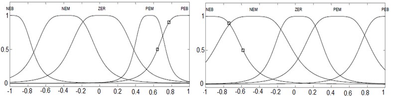
The layout of ANFIS controller for active suspension is depicted in Fig. 2. ANFIS is a combination of fuzzy logic and neural network in which neural network will be used to select the membership function in fuzzy logic. In ANFIS model, the steepest descent method as in neural network can be applied to modify the premise parameters and least square estimate can be applied to adapt the consequent parameters. The five linguistic terms are Negative Big (NEB), Negative Medium (NEM), Zero (ZER), Positive medium (PEM) and Positive Big (PEB) as show in in Fig. 3.
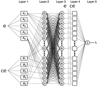
In this Type-2 TS fuzzy inference system, each membership function is modeled as linear function. The structure of ANFIS controller along with layers is shown in Fig. 4. The layer 1 creates membership values for each vector and . 1… 5. The output of layer 1 is modeled using bell shape membership function. The error and change in error values of suspension travel act as input to layer 1. The layer 2 consist of 25 nodes which belongs to 25 rules of fuzzy controller. This layer identifies the weights of each node by receiving input signal from layer 1. Each neuron in layer 3 mapped with fuzzy rules in such way that to calculated firing value of each rule. The layer 3 is non-adaptive and each node calculates the weighting function values:
Fig. 2Layout of ANFIS controller for active suspension
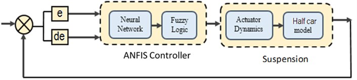
Fig. 3Input membership function for ANFIS
The layer 4 provides defuzzified values of inference mechanism which is obtained from fuzzy rules. The node calculate the output of this layer using following function. . Where is the output of layer 3. Parameters in this layer {; ; } are considered as the consequent parameters. The single node in layer 5 is non-adaptive which computes the overall output of this layer. The output of layer 4 are combined together to calculate the crisp value of controller:
Fig. 4Structure of layers in ANFIS controller
4. Simulation
The nonlinear half car model with hydraulic actuator dynamics was developed to perform simulation of active suspension. The Proportional Integral derivative (PID) controller was developed for Active suspension in order to compare the result of ANFIS control with PID and Passive suspension.
Fig. 5Response of heave and pitch angle for road Zr1
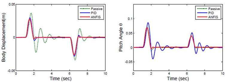
The response of body displacement and pitch angle is represented in Fig. 5. Table 3 lists root mean squared values of parameter of active suspension for sinusoidal road profile. The result shows that ANFIS controller has body displacement of 5.949 cm which is less than 8.604 cm of passive suspension. Similarly, the pitch angle of ANFIS controller is 6.156° which is considerably less than pitch angle of passive and PID controller. The ride comfort is also improved by means of the reduction of the body acceleration with the help of ANFIS controller.
Fig. 6Response of front suspension for road Zrf
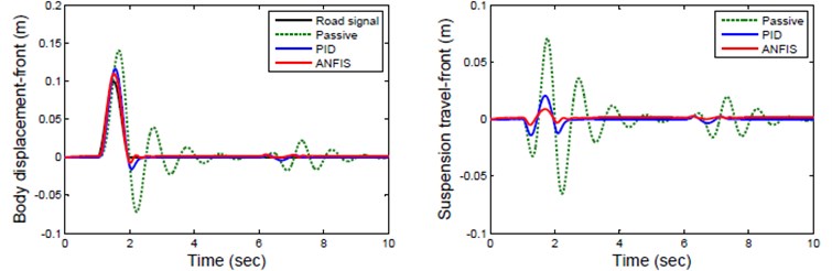
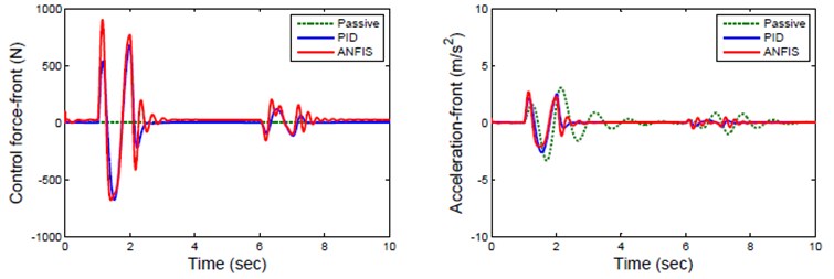
The response of front wheel for sinusoidal road profile is represented in Fig. 6 which indicates the response of passive, PID and ANFIS controlled active suspension for various suspension parameter. The Passive suspension of front wheel has high and long settling time compare to ANFIS controller which has less wheel displacement and settling time. The acceleration of ANFIS controlled suspension is significantly less than that of passive suspension.
Table 3Root mean squared values of parameter of active suspension
Parameter | Passive | PID | ANFIS |
Body displacement (cm) | 8.604 | 6.284 | 5.949 |
Pitch angle () | 9.446 | 6.875 | 6.1156 |
Acceleration (m/s2) | 0.68923 | 0.47682 | 0.46781 |
Fig. 7Response of rear suspension for road Zrr
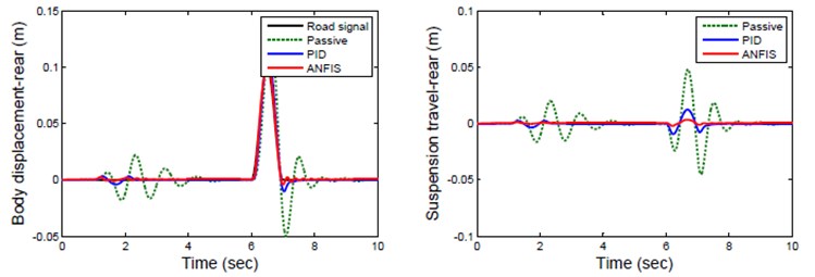
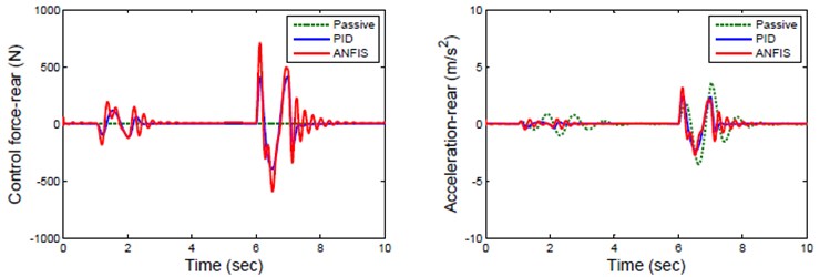
Fig. 8Response of active suspension for random road profile
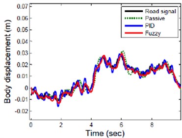
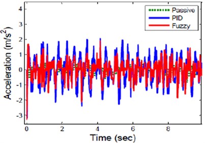
Hence a ANFIS controller reduces both body displacement and acceleration of front wheel better than passive suspension system. The response of rear wheel for sinusoidal road profile is represented in Fig. 7. The ANFIS controlled rear suspension has less peak displacement and settle quickly compare to Passive suspension of rear wheel which has long displacement and unstable. The response of active suspension for real road profile is shown Fig. 8. This result indicates that ANFIS controller reduces suspension travel and vertical acceleration amplitude of suspension significantly compare to passive and PID suspension.
5. Experimental validation
The real time control of active suspension used in this paper is shown in Fig. 9(a). The low cost experimental setup consists of a HILINK microcontroller board manufactured by Zeltom Educational and Industrial Control System Company, a corresponding Simulink library for Matlab/Simulink, DC motor with encoder, and quarter car suspension test rig. A pneumatic system with compressor simulate the various road profile for suspension system. The relative distance between sprung and unsprung mass can be measured by rack and pinion arrangement to control the suspension travel of active suspension system.
Fig. 9a) Quarter car suspension test rig, b) Zeltom-Hilink real time control board
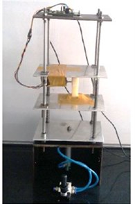
a)
b)
The HILINK microcontroller board includes D/A card and an encoder card as shown in Fig. 9(b). The displacement signal was send to the computer through HILINK board after it has been captured by the encoder. The captured signal was processed by Fuzzy controller in Simulink block to generate a current signal for HILINK output channel. The signal from HILINK output channel goes to amplifier which generates necessary actuator force for active suspension.
Fig. 10Response of suspension travel
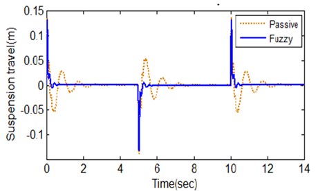
Table 4Root mean squared values of parameter of active suspension
Parameter | Experimental result | |
Passive | ANFIS | |
Body displacement (cm) | 8.1 | 5.31 |
Pitch angle () | 9.02 | 5.82 |
Acceleration (m/s2) | 0.654 | 0.321 |
The experiment is performed for final time of 14 seconds and the resulting response is shown in Fig. 10. It shows clearly that the active suspension has better control in reducing suspension travel in order to promote the road-holding capability of a car than with the passive suspension. The experimental value in Table 4 indicates that the ride comfort of the passengers is improved greatly by using the proposed ANFIS controller. This experimental result shows that ANFIS controlled active suspension for half car model provides better ride comfort and stability than passive suspension system.
6. Conclusions
Adaptive neuro fuzzy inference system (ANFIS) controller will be proposed for hydraulic actuated active suspension system due to the difficulty of deriving mathematical model of active suspension. The multivariable, nonlinear and uncertainty in actuator has increased the difficulty design of conventional controller so that it will not perform well. In this paper, Hybrid intelligent control consist of neural network and fuzzy logic has been implemented to adapt the actuator dynamics and model uncertainty in active suspension. The performance of fuzzy logic depends on membership function which has been desired by knowledge of expert. Hence, neural network is used to train the membership function and control rules of fuzzy logic in order to improve the performance of controller. The simulation is carried out for sinusoidal road profile where the body displacement and pitch angle of ANFIS controlled active suspension system is significantly less compare to PID controlled suspension system. The result of simulation indicates performance of the ANFIS controlled half car model based active suspension with actuator dynamics.
References
-
Chen P. C., Huang A. C. Adaptive sliding control of active suspension systems with uncertain hydraulic actuator dynamics. Vehicle System Dynamics, Vol. 44, Issue 5, 2006, p. 357-368.
-
Yu M., Choi S. B., Dong X. M., Liao C. R. Fuzzy neural network control for vehicle stability utilizing magnetorheological suspension system. Journal of Intelligent Material System, Vol. 20, Issue 4, 2009, p. 457-466.
-
Eski I., Yildirim S. Vibration control of vehicle active suspension system using a new robust neural network control system. Simulation Model Practice Theory, Vol. 17, Issue 5, 2009, p. 778-793.
-
Montazeri Gh M., Soleymani M. Genetic optimization of a fuzzy active suspension system based on human sensitivity to the transmitted vibrations. Proceedings of the Institution of Mechanical Engineers, Part D: Journal of Automobile Engineering, Vol. 222, Issue 10, 2008, p. 1769-1780.
-
Kim D., Hwang S., Kim H. Vehicle stability enhancement of four wheel- drive hybrid electric vehicle using rear motor control. IEEE Transaction of Vehicle Technology, Vol. 57, Issue 2, 2008, p. 727-735.
-
Hrovat D. Optimal active suspension structures for quarter-car vehicle models. Automatica, Vol. 25, Issue 5, 1990, p. 845-860.
-
Thompson A., Davis B. Optimal linear active suspensions with derivative constraints and output feedback control. Vehicle. System Dynamics, Vol. 17, Issue 4, 1988, p. 179-192.
-
Thompson A., Davis B. A technical note on the lotus suspension patents. Vehicle System Dynamics, Vol. 20, Issue 6, 1991, p. 381-383.
-
Louam N., Wilson D. A., Sharp R. S. Optimization and performance enhancement of active suspensions for automobiles under preview of the road. Vehicle System Dynamics, Vol. 21, Issue 12, 1992, p. 39-63.
-
Huisman R. G. M., Veldaus F. E., Voets H. J. M., Kok J. J. Optimal continuous time control strategy for active suspension with preview. Vehicle System Dynamics, Vol. 22, Issue 1, 1993, p. 43-55.
-
Abdel Hady M.-B.-A. Active suspension with preview control. Vehicle System Dynamics, Vol. 23, 1994, p. 1-13.
-
Langlois R. G., Hanna D. M., Anderson R. J. Implementing preview control on an off-road vehicle with active suspension. Vehicle System Dynamics, 20, p. 340-353.
-
Yoshimura T., Edokoro K., Ananthanarayana M. Active suspension model for rail/vehicle systems with preview and stochastic optimal control. Journal of Sound Vibration, Vol. 166, Issue 3, 1993, p. 507-519.
-
Alleyne A., Hedrick J. K. Nonlinear adaptive control of active suspensions. IEEE Transactions on Control Systems Technology, Vol. 3, Issue 1, 1995, p. 94-101.
-
Hrovat D. Survey of advanced suspension developments and related optimal control applications. Automatica, Vol. 33, Issue 10, 1997, p. 1781-1817.
-
Williams R. A. Automotive active suspensions Part 1: Basic principles. Proceedings of the Institution of Mechanical Engineers, Part F: Journal of Rail and Rapid Transit, Vol. 211, Issue 6, 1997, p. 415-426.
-
Rao M. V. C., Prahlad V. A tunable fuzzy logic controller for vehicle active suspension systems. Fuzzy Sets Systems, Vol. 85, Issue 1, 1997, p. 11-21.
-
D’amato F. J., Viassolo D. E. Fuzzy control for active suspensions. Mechatronics, Vol. 10, Issue 8, 2000, p. 897-920.
-
Huang W., Lin S. J. C. Adaptive fuzzy controller with sliding surface for vehicle suspension control. IEEE Transaction on Fuzzy System, Vol. 11, Issue 4, 2003, p. 550-559.
-
Mittal R., Bhandari M. Design of robust PI controller for vehicle active suspension system with hydraulic actuator. IEEE International Conference on Communications and Signal Processing, 2015, pp.914-0918.
-
Chantranuwathana S., Peng H. Adaptive robust force control for vehicle active suspensions. International Journal of Adaptive Control and Signal Processing, Vol. 18, Issue 2, 2004, p. 83-102.
About this article

