Abstract
This paper investigates the design and verification of a hybrid model predictive controller of a damping multi-mode switching damper for application in vehicle suspensions. Since the damping mode switches induce different modes of operation, the vehicle suspension system including this damper poses challenging hybrid control problem. To solve this problem, a novel approach to the modelling and controller design problem is proposed based on hybrid modelling and model predictive control techniques. The vehicle suspension system with the damping multi-mode switching damper is formulated as a mixed logical dynamical model comprising continuous and discrete system inputs. Based on this model, a constrained optimal control problem is solved to manage the switching sequences of the damping mode with respect to the suspension performance requirements. Numerical simulation results demonstrate the effectiveness of the proposed control methodology finally.
1. Introduction
Suspension system plays an important role in providing a high level of ride comfort by isolating the vehicle body from road irregularities and improving road holding capacity by preventing the wheel from loosing road contact [1-3]. It is well known that these are conflicting requirements and many studies have shown that this conflict can be eased by using controlled suspension systems instead of passive ones [4, 5]. Especially semi-active suspension system has attracted much attention due to its performance increase compared to passive suspensions and its low energy consumption compared to active systems [6, 7].
Since the works of Karnopp who has proposed the skyhook algorithm in order to improve the ride comfort [8], many different semi-active suspension control approaches have been developed, ranging from simple on-off control strategy to much more advanced linear and nonlinear control techniques. Ahmadian et al proposed an extension of skyhook control algorithm for eliminating dynamic jerk of semi-active suspension [9]. Fallah et al. investigated the performance of a robust control scheme for a semi-active Macpherson suspension system [10]. A new semi-active suspension control strategy through linear parameter varying (LPV) technique has been considered in Vassal et al. [11]. Application of the LQ-based semi-active suspension control was presented in Unger et al. [12]. In Zhang et al. [13], a sliding mode controller (SMC) was developed for semi-active suspension. According to these past studies, different control algorithms have different advantages with respect to different aspects of suspension performance.
Meanwhile, as a crucial semi-active device, the design of variable damping damper is an important aspect for semi-active suspension system [14]. In early semi-active suspension, the damping force regulating is achieved by adjusting the orifice area in the oil-filled damper, but the damping changing speed is much slow for using of mechanical motion. More recently, the possible applications of magnetorheological (MR) fluids in providing controllable damping forces are investigated and the MR dampers have become the viable candidates for semi-active control of vehicle suspension systems [15]. A variety of control algorithms, such as neural network control, fuzzy logic control and gain-scheduled control, have also been proposed for the semi-active suspension control with MR dampers. To consider the nonlinear dynamic characteristics of MR dampers in the control system design process, a Takagi-Sugeno (TS) fuzzy model-based control strategy was proposed by Du et al. [16]. A new adaptive fuzzy controller and its implementation for the damping force control of a MR fluid damper was studied in [17]. Prabakar et al. investigated the optimal semi-active preview control response of a half car vehicle model with MR damper [18]. Yao et al. employed a skyhook control strategy to control an MR damper for a vehicle suspension system [19].
Although several types of variable damping damper and the corresponding control strategies have been developed in the past few decades, the semi-active suspension system still remains an open research area. In this paper, a new type damping controllable damper is chosen as the research object. This new damper involves a conventional monotube hydraulic damper and a damping adjustment device which includes several hydraulic valves. Compared with the well-known MR damper, which has excellent damping adjustment capability, the new damper is cheaper and more stable. In addition, the new damper can achieve four different damping modes by just controlling the on-off statuses of two solenoid valves, which makes its damping control more efficient and more reliable.
The semi-active suspension system with this damper will perform transitions from one discrete damping state to another at certain nonpredetermined instances of time, i.e. the system has hybrid properties from which arise the difficulties in the damping control of the vehicle suspension [20]. In general, this new damper features four different modes of operation, where each mode has a related linear continuous dynamic equation. Furthermore, the manipulated variables of the control problem (the valve on-off status) are discrete, which cannot be handled directly by the conventionally continuous control methods, thus the hybrid approach is considered in this paper.
Hybrid system is proposed to describe a class of systems where continuous dynamics and discrete events interact and their interaction determines the qualitative and quantitative system behaviours [21-23]. Recently, there have been many proposals to apply new results from hybrid system theory to address advanced control problems in engineering. Borrelli et al solved a traction problem by using the hybrid framework and the optimization-based control strategy [24]. Corona et al designed a semi-active suspension system on the basis of the optimal control of hybrid automata [25]. A control strategy to coordinate active front steering and differential braking to improve vehicle yaw stability was proposed by Cairano et al. [26]. The vehicle dynamics with respect to the tire slip angles was formulated as a piecewise affine (PWA) system and the system controller was synthesized by using a switched hybrid model predictive control (MPC) strategy. To solve a two-level hierarchical management and control problem for a smart microgrid, the hybrid control theory was used based on discrete Petri-net model [27]. According to these previous researches, the MPC method has emerged as a very useful means for controlling the hybrid system. Based on the hybrid model, a constrained finite time optimal control problem can be formulated by tuning a model predictive controller.
Motivated by these studies, we present a novel approach to the modelling and controller design problem for the vehicle semi-active suspension system with the damping multi-mode switching damper. This approach can lead to a state-feedback controller that considers the suspension performance and yield the status direct control of the on-off solenoid valves. In particular, this controller can also be implemented in the form of a lookup table, thus avoiding online real-time optimization for practical application [28].
This paper is arranged as that initially the target variable damping damper will be described and modelled. In the next section, the hybrid dynamical model of the vehicle suspension system including the damping multi-mode switching damper is formulated as a mixed logical dynamical model comprising continuous and discrete system inputs. Based on this model, a hybrid model predictive controller (HMPC) is tuned by using online mixed-integer quadratic optimization. The simulations results are then presented to illustrate various aspects of the system’s behaviours. Finally, some conclusions are drawn.
2. Damping multi-mode switching damper
2.1. Operating principle of the damper
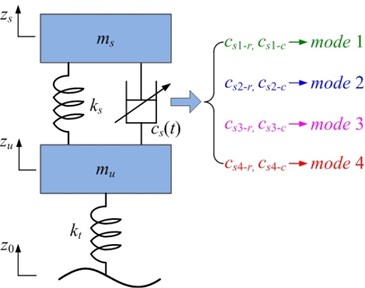
The fundamental structure of the target damping multi-mode switching damper is shown in Fig. 1, which mainly includes a conventional monotube hydraulic damper that is made up of a piston rod, three chambers (rebound, compression and air chambers), two valves (rebound and compression valves) and a floating piston. Due to the use of the floating piston, a set of hydraulic valves can be saved, thus the number of the accessory is reduced by 15 % [29]. The high-pressure air in the air chamber also can increase the critical velocity of the damper. The piston rod motion changes the pressures of the three chambers, and then drives the hydraulic oil to flow between different chambers through the hydraulic valves. The damping adjustment is achieved by four different check valves and two on-off solenoid valves. By changing the on-off status of the two solenoid valves, the hydraulic oil flow path can be changed, thus different damping modes are achieved.
The four damping modes of the damper are summarized in Table 1 where the solenoid valve on-off statuses and the damping characteristics of the four modes are given. The oil flow paths of the different damping modes are depicted in Fig. 2. It is noted that to achieve the different damping characteristics of the compression stroke and the rebound stroke, different types of check valve, which have different pressure losses for the oil flow, are used in the damping adjustment device. Concretely speaking, the hydraulic oil flow pressure loss of the check valve a is greater than that of the check valve , while the oil flow pressure loss of the check valve is less than that of the check valve .
Fig. 1Structure of the damping multi-mode switching damper
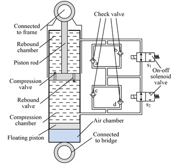
Fig. 2Hydraulic oil flow paths of different damping modes
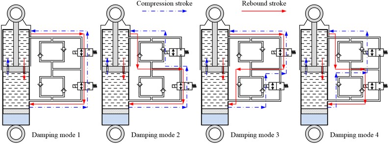
Table 1Damping modes of the damper
Damping mode | On-off status | Damping characteristic | ||
Compression | Rebound | |||
1 | on | on | Soft | Soft |
2 | off | on | Soft | Hard |
3 | on | off | Hard | Soft |
4 | off | off | Hard | Hard |
2.2. Mathematical modelling of the damper
When constructing the model of the hydraulic damper, the following assumptions are made to reduce the complexity and to get a solvable set of mathematical equations [30, 31].
1) There is no oil flow leakage between the piston rod and the guide sleeve and also between the piston and the cylinder.
2) The oil temperature remains constant in an operating cycle which includes a compression stroke and a rebound stroke.
3) The gravitational potential energy of the oil is neglected.
4) The instantaneous pressure of the oil is equal in all closed chambers.
5) The oil mass consumed by the oil bubble produced in the throttling process can be ignored.
2.2.1. Analysis for damping force
Ignoring the friction force, the ultimate damping force generated by the target damper is expressed as [32]:
where is the damping force in the rebound stroke, is the damping force in the compression stroke, refers to the oil pressure in the rebound chamber, refers to the oil pressure in the compression chamber, and represent the effective piston areas in compression and rebound chambers, and represent the differential pressures between the rebound chamber and the compression chamber.
2.2.2. Oil flow equations of damping mode 1
The oil flow rate from the rebound chamber to the compression chamber in the rebound stroke can be divided into two parts. One part is the oil flowing through the damping adjustment device and the other part is the oil flowing through the rebound valve . Thus, the oil flow rate from the rebound chamber to the compression chamber can be expressed as:
where refers to the velocity of the piston.
Meanwhile, the oil pressure loss during the flow process is given by:
where and are the oil pressure losses through the damping adjustment device and the rebound valve respectively.
Since two on-off solenoid valves are connected in series in the damping adjustment device, can be further described as:
where denotes the oil pressure loss through the solenoid valve , represents the oil pressure loss through the solenoid valve .
The on-off solenoid valve can be regarded as a thin-wall orifice; thus the oil pressure loss is given by [33]:
where is the oil density, is the pressure loss coefficient, refers to the area of the orifice.
The throttling form of the rebound valve is also divided into two parts. The first part is the oil flowing through the slender orifice and the oil pressure loss is expressed as:
where is the oil kinematic viscosity, is the throttling length of the slender orifice, is the diameter of the slender orifice. The other part is the oil flowing through the gap between the valve slice and the end surface of the piston, which can be regarded as the annular plane gap throttling. Thus, the oil pressure loss is given by:
where denotes the outer radius of the valve slice, denotes the inner radius of the valve slice, denotes the deformation of the valve slice, which is further obtained by using conjugate beam method as [34]:
where refers to the oil pressure subjected by the valve slice, refers to the modulus of elasticity of the valve slice, refers to the valve slice thickness.
In addition, in order to ensure that the oil is filled in the compression chamber, the floating piston will also move and the volume change of the air chamber is given by:
where represents the displacement of the piston. Then, the relationship between the states of the air in the air chamber can be described using polytropic equation as:
where is the initial air pressure in the air chamber, is the initial volume of the air chamber, is the polytropic index. We assume that the piston movement is relatively balanced, thus the oil pressure in the compression chamber is equal to the air pressure in the air chamber.
According to the aforementioned simultaneous equations, the damper rebound damping force of damping mode 1 can be calculated. Since the damping force in the compression stroke can be calculated similarly, the specific calculation process is omitted here.
2.2.3. Oil flow equations of damping modes 2 and 3
Since the oil flow of damping modes 2 and 3 are similar, we analyse the oil flow equations of the two modes together, and take the mode 2 as an example.
The main difference of the oil flow between the damping mode 1 and the damping mode 2 is that the oil of the latter flows through a check valve in the damping adjustment device. Therefore, for the rebound stroke, the oil pressure loss through the damping adjustment device of damping mode 2 can be obtained as:
where is the oil pressure loss through the check valve , which can be expressed as:
where refers to the rated pressure loss of the check valve , refers to the rated flow rate of the check valve . These two variables have fixed values for the check valve. Hence, the oil pressure losses through the damping adjustment device of damping mode 2 and 3 are summarized as:
where , and are the rated pressure losses of the check valve , check valve and check valve respectively, , and are the rated flow rates of the check valve , check valve and check valve respectively.
2.2.4. Oil flow equations of damping mode 4
In order to achieve the both hard damping characteristics in the rebound and compression stroke, the two on-off solenoid valves are closed in damping mode 4. Thus, the oil pressure loss through the damping adjustment device is given by:
The other oil flow equations of the rebound valve and the compression valve can be got from Eq. (6) to (10).
2.3. Damping characteristics simulation
On the basis of the aforementioned mathematical model of the damping multi-mode switching damper, the damping characteristic is analysed by simulations. The major simulation parameters of the damper are listed in Table 2. The indicator characteristic curves of the four damping modes and the related velocity characteristic curves are shown in Figs. 3-4.
Table 2Simulation parameters of the damper
Parameter | Value | Parameter | Value |
0.0013 m2 | 0.2668 mm | ||
3.14×10⁻⁴ m2 | 0.92 MPa | ||
835 kg.m-3 | 1.34×10⁻⁴ m3 | ||
0.62 | 1.8 MPa | ||
7.068×10⁻⁶ m2 | 1.6MPa | ||
0.015 Pa·s | 1.6 MPa | ||
0.015 m | 1.8 MPa | ||
0.002 m | 1.2 L.min-1 | ||
0.018 m | 1.5 L.min-1 | ||
0.01 m | 1.2 L.min-1 | ||
2.06×10⁵ MPa | 1.0 L.min-1 |
Fig. 3Indicator characteristics of the damper
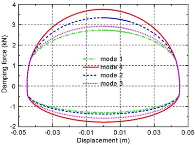
Fig. 4Velocity characteristics of the damper
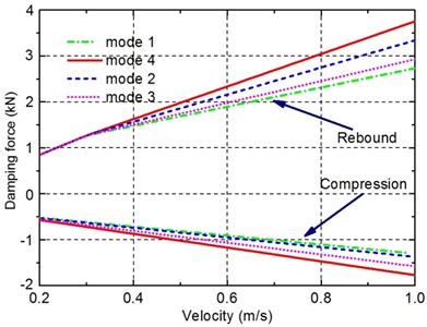
It can be seen from Figs. 3-4 that significantly different damping characteristics of the damper for four damping modes are achieved. The indicator diagram area and the slopes of the velocity characteristics curve of mode 4 are larger than that of the other three modes, which means its relatively hard damping characteristics. It is also observed from Fig. 4 that the curves of the velocity characteristics tend to be approximate linear, thus the damping coefficients of the damper can be calculated to establish the hybrid model of the vehicle suspension system including this damper in the next section.
A reliable mathematical model is very essential to study the damping characteristics of the damper, for instance, to model the nonlinear behaviors of the MR dampers, different forms of the mathematical models, including the parametric model and the non-parametric model, have been proposed, and many of them are verified by experimental tests [35-38]. In this paper, although the mathematical model of the damping multi-mode switching damper is only verified by simulations, it is noted that this damper is proposed based on a conventional monotube hydraulic damper, whose mathematical model has been studied for many years and verified by experiments in the references. In addition, the damping adjustment device of the new damper is constructed by several hydraulic valves, which are not so complicated as the damping adjustment device of the MR damper or the electrorheological (ER) damper. The models of the hydraulic valves are also very mature.
To identify the MR damper characteristics, which includes the transient response of the MR force due to the electric current change; the MR force relation with the displacement and velocity of the damper rod; the hysteresis; and the effect of the manipulation shape, Lozoya-Santos et al. proposed a design of experiments that exhaustively explore the behaviors of an automotive MR damper [39]. In this paper, to model the vehicle semi-active suspension system which includes the new damper as a hybrid system, the nonlinear damping behaviors are not be considered and the linearization of the nonlinear damping characteristics is conducted. Moreover, since the new damper can only achieve four damping modes, from the view of effective damping control of the suspension, the nonlinear effects on the damping characteristics need to be ignored.
3. Hybrid modelling of the vehicle suspension system including the damper
3.1. Quarter-car model with the multi-mode switching damper
The quarter-car model with the damping multi-mode switching damper depicted in Fig. 5 is considered here in designing the hybrid control law. The equations of motion for the sprung and unsprung masses are governed by:
where refers to the sprung mass, refers to the unsprung mass, denotes the stiffness of the spring, is the stiffness of the tire, and represent the displacements of the sprung and unsprung masses respectively, refers to the road displacement input, are the variable damping coefficients which depend on the damping mode, among of which, and refer to the damping coefficients in the rebound and compression strokes of damping mode 1, and are the corresponding damping coefficients of damping mode 2, and represent the corresponding damping coefficients of damping mode 3, and represent the corresponding damping coefficients of damping mode 4.
Fig. 5Quarter-car model with the damping multi-mode switching damper
3.2. Mixed logical dynamical (MLD) modelling of the vehicle suspension system
Since the damping mode of the damper depends on the on-off status of the solenoid valves, the optimal control of the damping characteristics for the vehicle suspension must deal with both the continuous and discrete variables, which can be regarded as a typical hybrid system control problem. Therefore, the MLD framework, which is an effective modelling method for hybrid systems [40], is used to achieve the systematic design procedure of the overall controller of the damping multi-mode switching damper for application in vehicle suspensions.
The general MLD form of a hybrid system is given by:
where denotes the continuous and binary states, represents the continuous and binary inputs, represents the continuous and binary outputs, and are the auxiliary binary and continuous variables, respectively. The evolution of the states is described by the state matrix and the input matrices . Similarly, the output matrix and the matrices describe the evolution of the outputs. define the inequalities of the system.
3.2.1. Hybrid systems description language (HYSDEL)
Once the system MLD model is available, the formulation of optimal control law for hybrid system can be achieved. Hence, the development of the system MLD model is critical for achieving the damping mode switching control in this study. However, for complex dynamic system, the establishment of MLD model is inefficient and tedious. To solve this problem, HYSDEL, which is a high-level modelling language for describing hybrid systems, is designed in [41]. The associated HYSDEL compiler can translate the description of the hybrid system into the MLD model directly, which makes it easy to build the system model.
The HYSDEL list is composed of two parts. The first one, which contains the declaration of all variables and parameters, is called “interface”, and it is subdivided into four sections: state, input, output and parameter. The second part, which is composed of nine specialized sections: automata, linear, logic, ad, da, aux, continuous, must and output, where all the relations among the variables are described, is called “implementation”. The sample HYSDEL list of system is shown in Table 3.
In the next few sections, how the dynamic model of the quarter-car suspension with the multi-mode switching damper can be described as a MLD system based on the HYSDEL will be explained in detail.
Table 3Sample HYSDEL list of system
SYSTEM sample{ INTERFACE{/* declaration of variables and parameters */ STATE{/* declaration of state variables */} INPUT{/* declaration of input variables */} OUTPUT{/* declaration of output variables */} PARAMETER{/* declaration of system parameters */}} IMPLEMENTATION{/* relations between variables */ AUX{/* declaration of auxiliary variables */} CONTINUOUS{/* continuous state update equation */} AUTOMATA{/* binary state update equation */} LINEAR{/* linear relations between continuous variables*/} LOGIC{/* logical relations between binary variables */} AD{/* relations between variables of type real to bool */} DA{/* relations between variables of type bool to real */} MUST{/* specification of input/state/output constraints*/} OUTPUT{/* selection of output variables */}}} |
3.2.2. Declaration of variables and parameters
According to the system motion equations, the state variables are defined as:
To achieve the switching of the damping mode, the on-off statuses of the solenoid valves and the road displacement are defined as the input variables:
where refers to the on-off status of the solenoid valve , refers to the on-off status of the solenoid valve . The output variables are defined for considering the concerned suspension performance indices as:
Meanwhile, the parameters of the quarter-car suspension model with the multi-mode switching damper, considered in simulation calculations, are listed in Table 4.
Table 4Parameter values of the quarter-car suspension
Parameter | Value | Parameter | Value |
425 kg | 2992 N·s·m-1 | ||
60 kg | 1047 N·s·m-1 | ||
29500 N·m-1 | 2393 N·s·m-1 | ||
192000 N·m-1 | 1272 N·s·m-1 | ||
2112 N·s·m-1 | 3590 N·s·m-1 | ||
968 N·s·m-1 | 1483 N·s·m-1 |
3.2.3. Declaration of auxiliary variables
The on-off statuses of the solenoid valves represented by the defined logical input variables are defined as:
On this basis, the four damping modes of the damper are represented by the following four auxiliary variables:
where , , and are the auxiliary logical variables, and they have the following relationships with and :
Since the different damping characteristics of the damper considered in the compression and rebound strokes, we define two auxiliary logical variables to denote the different stroke:
Hence, the variable damping coefficient of the damper can be obtained as:
where , , , , , , and are the auxiliary logical variables, and they are defined as:
By defining the auxiliary continuous variables on the basis of Eq. (23):
The variable damping coefficients of the damper can then be further given by:
where , , , , , , and represent the auxiliary continuous variables. It is noted that since the status of the solenoid valve can only switch between the “on” and the “off”, thus four damping modes can be formed uniquely by the on-off status combination of the two solenoid valves. Therefore, the new damper does not have intermediate operating points between the four damping modes actually. Hence, the variable damping coefficients of the new damper can be represented by the equations mentioned above.
3.2.4. Update equations for state variables
Because of the discrete-time nature of the MLD model, the derivatives of the state variables are further described as:
where is the sample time. On this basis, according to Eq. (15) and (27), the update equations for state variables, which would be used in the MLD modelling, can be obtained as:
3.2.5. Additional logical constraints
Apparently, there are some constraints on the defined logical variables according to the system actual working process:
Contrary to the optimization over continuous variables, the additional logical constraints on variables can help solving the mixed-integer programming problem significantly, which is the key for tuning a hybrid model controller.
After defining the system variables and confirming their update equations and logical relationships, the corresponding MLD model of the vehicle suspension system with the damping multi-mode switching damper can then be obtained as Eq. (16) automatically by processing the HYSDEL description as mentioned above. In this study, the HYSDEL version 3.0 is used and an encapsulation module called “HYSDEL model” is obtained [42], which includes three inputs and three outputs. The total number of the MLD inequalities is 82, which are omitted here for lacking of space.
4. Hybrid model predictive controller design
In this section, a novel approach towards the optimal control of damping mode switching of the damper is proposed based on model predictive control (MPC) with a receding horizon policy. The main idea of MPC is to solve a constrained optimal control problem at each sampling instant over a finite horizon using the current state as the initial state. The solution to the problem yields an optimal control sequence that minimizes a given objective function. Moreover, a receding horizon policy can be achieved by only applying the first control input in the sequence and by recomputing the control sequence at the next sampling instant [43]. Another important reason for choosing MPC as the approach to control the damping modes in this work is that the established MLD model can be embedded in MPC as prediction model straightforwardly [44]. Furthermore, MPC can also deal with hard constraints on the manipulated variables, states and outputs.
4.1. Control objectives
The control objectives for vehicle suspension in this work can be classified into two priority levels. The main objective is to guarantee the ride comfort, road holding capacity and minor suspension deflection. The ride comfort can be reflected by the vertical acceleration of sprung mass, which is the main control objective that needs to be optimized. Meanwhile, to improve vehicle handling ability and driving safety, a firm uninterrupted contact of wheel with the road is also important. Thus, the dynamic tyre load, , which quantifies the road contact ability, should also be small. In addition, due to the constrained structure of the vehicle, the suspension deflection, , needs to be limited to reduce the probability of suspension reaches the mechanical end stop [45].
The control objective with secondary priority is to prevent the frequent switching of the on-off statuses of the solenoid valves, which will reduce the operating lifespan of the solenoid valve. This is achieved by minimizing the number of switch transitions within the prediction interval.
4.2. Objective function
On the basis of the aforementioned controller objectives, the mathematical expression of the objective function, which comprises a number of cost expressions, will be defined.
In order to satisfy the suspension performance requirements, a reference vector for outputs and the corresponding penalty matrix are defined as:
where , and denote the penalty weighting parameters for the system outputs.
To prevent the frequent switching of the on-off status of the solenoid valves, the difference between four consecutive control inputs are introduced as:
On this basis, the vector for the difference between four consecutive control inputs and the penalty matrix are given by:
Hence, a cost function accounting for optimal control of the damping characteristics and adherence to the suspension performance requirements is obtained in 2-norm as:
which penalizes the predicted evolution of the system outputs and the control inputs from time instant over the finite horizon .
4.3. Computation of the control inputs
Based on system MLD model Eq. (16) and the objective function Eq. (35), the control inputs at time-instant are then obtained by minimizing the objective function over the sequence of control inputs subject to the mixed-integer inequality constraints. This amounts to a constrained finite time optimal problem [46]:
which leads to the sequence of optimal control inputs, of which only the first element of the optimizer is used as control inputs at time-instant , while the procedure is repeated from newly estimated/measured state at the following control cycle. Since the 2-norm used in the objective function, the problem Eq. (36) can be formulated as a mixed-integer quadratic program (MIQP) problem, for which efficient solvers exist [47]. Given the value of the current state, the MIQP can be solved to obtain the optimal input sequence. Moreover, by applying multi-parametric programming technique, where the state is considered as a parameter [48], the explicit form of the optimal state feedback control law can be obtained. This can reduce the online complexity to the just simple evaluation of a piecewise affine function, which makes the approach easy to application.
5. Simulation study
To evaluate the close-loop behavior of the vehicle suspension system with the damping multi-mode switching damper and demonstrate the potential advantages of the proposed control methodology, numerical simulation results are presented in this section. Since there are no previous researches about the damping control of the vehicle semi-active suspension system with the damping multi-mode switching damper and no relevant control approaches are proposed, a skyhook controller designed for the conventional semi-active suspension with damping continuously adjustable damper is adopted for comparison purpose. The skyhook controller determines the desired damping force as [49]:
where is the skyhook gain. Hence, we will compare the performance of the hybrid model predictive controller and the skyhook controller with the passive suspension. Among these, the performance simulation of the hybrid model predictive controller is carried out using the MLD model as the real plant, closing the loop with the controller designed.
Furthermore, two types of road irregularity excitations, which represent the major disturbance acting on the vehicle suspension, are chosen to model the real-world road roughness. Among them, the bump input, which is normally used to reflect the transient response characteristic, is adopted as the first road excitation.
5.1. Simulation analysis of the bump responses
The first road irregularity excitation is a long shaped single bump input, which is normally used to describe the transient response characteristics of the vehicle suspension. Considering the case of a bump in a smooth road surface, the corresponding road displacement input is given by [50]:
where is the height of the bump, is the length of the bump, is the vehicle forward velocity.
In the simulation, the values of and are set to 0.1 m and 0.85 m respectively, the vehicle forward velocity is set to 1.5 m/s. By applying the bump road excitation input to the suspension, the transient responses of the passive suspension, where a conventional damper with a damping coefficient of 1800 N.s.m-1 (denoted as Passive), the semi-active suspension with a skyhook controller (denoted as Skyhook), and the vehicle suspension with the damping multi-mode switching damper (denoted as HMPC) are compared in Figs. 6-8.
Fig. 6Time responses of the sprung mass acceleration under bump road input
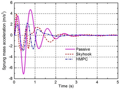
Fig. 7Time responses of the suspension deflection under bump road input
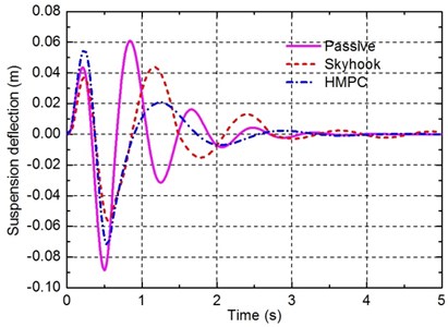
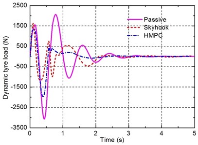
Fig. 8Time responses of the dynamic tyre load under bump road input
In order to better compare the dynamic performance of the three suspensions under the bump input, the peak-to-peak (PTP) values for sprung mass acceleration, suspension deflection, and dynamic tyre load are illustrated in Table 5.
Table 5PTP values comparison under bump road input
Performance | Passive | Skyhook | HMPC | ||
PTP | PTP | Decrease | PTP | Decrease | |
(m/s2) | 11.86 | 6.75 | 43.1 % | 5.19 | 56.2 % |
(m) | 0.15 | 0.1000 | 33.3 % | 0.13 | 14.9 % |
(N) | 5134 | 2813 | 45.2 % | 3354 | 34.7 % |
It can be seen from Fig. 6 and Table 5 that better response of the sprung mass acceleration is obtained for the suspension controlled by HMPC compared to the passive suspension and the semi-active suspension with a skyhook controller. However, from Figs. 7 and 8, it can be found that although the responses of the suspension deflection and the dynamic tyre load of the suspension controlled by HMPC are still better than that of the passive suspension, the improvement amplitudes are less than that of the semi-active suspension with a skyhook controller. This is assumed to be caused by two reasons. The first is that the penalty weight for the sprung mass accelerationis set much greater than the others weights to emphasize the ride comfort as the primary control objective. The other reason is that the damping mode of the damper studied in this work is, after all, limited, thus it is difficult to achieve better performance for all the performance requirements than the conventional semi-active suspension with continuously adjustable damper. However, the better performance of the conventional semi-active suspension is achieved based on the real-time control of the damping force, which is often difficult, hence, the performance of the vehicle suspension with the damping multi-mode switching damper controlled by HMPC is more reliable and easy to implement.
5.2. Simulation analysis of the random road responses
To further validate the effectiveness of the proposed control approach, a second type of road irregularity excitation, a random road profile, is applied. The time domain representation of the random road profile is approximated by rational function [51]:
where denotes the road roughness coefficient, is the Gaussian white noise with mean value zero. In order to obtain the simulation calculation results, we assume that the vehicle is driven on a rough road corresponding to the class B of ISO road profiles at 72 km/h [52].
In this case, the time responses of the passive suspension, the semi-active suspension with a skyhook controller and the suspension with the damping multi-mode switching damper are compared. Figs. 9-11 show the responses of the sprung mass acceleration, the suspension deflection and the dynamic tyre load under random road input. Moreover, to better compare the performance of the three suspensions, the RMS values of the three suspension performance criteria are also listed in Table 6.
Table 6RMS values comparison under bump road input
Performance | Passive | Skyhook | HMPC | ||
RMS | RMS | Decrease | RMS | Decrease | |
(m/s2) | 0.604 | 0.447 | 25.99 % | 0.311 | 48.51 % |
(m) | 0.0054 | 0.002990 | 46.30 % | 0.0034 | 37.04 % |
(N) | 430.2 | 297.1 | 30.94 % | 278.7 | 35.22 % |
As shown in Figs. 9-11 and table 6, similar conclusions can be obtained for this case where the designed damper and the corresponding HMPC approach are effective in improving suspension performance. In particular, the suspension with the damping multi-mode switching damper controlled by HMPC can reduce the RMS values of the sprung mass acceleration and the dynamic tyre load by 48.51 % and 35.22 % respectively, compared with the conventional passive suspension. These improvement amplitudes are even larger than that of the semi-active suspension with damping continuously adjustable damper controlled by a skyhook controller, which confirms that better performance of the vehicle suspension can be achieved by the damper and the control approach proposed in this work.
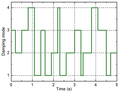
Fig. 12 shows the on-off statuses of the solenoid valves given by HMPC when the random road input is acted on the vehicle suspension. On this basis, the damping modes of the multi-mode switching damper are also depicted in Fig. 13. It can be seen from Figs. 12 and 13 that the designed controller using hybrid system theory and MPC technique can derive an effective control law for the discrete on-off statuses of the solenoid valves, which verifies the effectiveness of the proposed control approach for solving optimal control problem of hybrid systems.
Fig. 9Time responses of the sprung mass acceleration under random road input
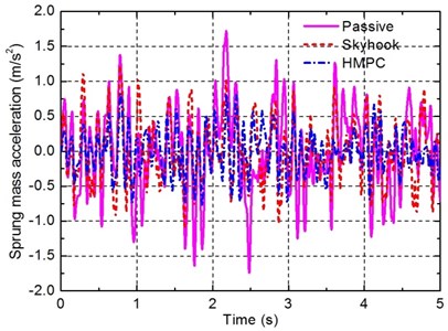
Fig. 10Time responses of the suspension deflection under random road input
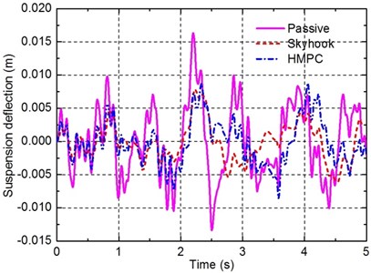
Fig. 11Time responses of the dynamic tyre load under random road input
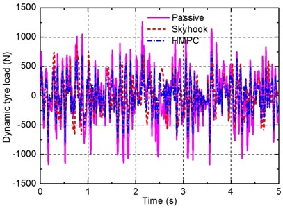
Fig. 12On-off statuses of the solenoid valves
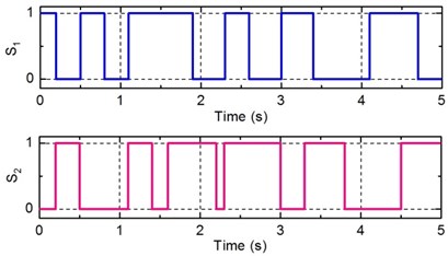
Fig. 13Damping mode transitions
Due to the hybrid properties arising from the damping control process of the vehicle semi-active suspension system with the damping multi-mode switching damper, the hybrid model predictive controller designed in this paper is the only effective control strategy that we can provide currently. It is also noted that since the system MLD model only allows specifying the evolution of continuous variables through linear dynamic equations, the nonlinear damping characteristics of the damping multi-mode switching damper are ignored during the system hybrid modeling process, thus the actual performance of the designed hybrid model predictive controller may be limited to a certain extent. In the further studies, we consider to conduct the comparison between the performances of the hybrid model predictive controller with other effective hybrid control strategies.
6. Conclusions
This paper investigates the design and validation of a hybrid model predictive controller towards a new type damping controllable damper for application in vehicle suspensions. By establishing the mathematical model of the damper, obviously different damping characteristics of the damper can be derived for different damping modes. On this basis, to obtain optimal suspension performance, a system controller is design using hybrid model predictive control approach. This approach has the advantage of designing a controller directly dealing with discrete manipulated variable, that is, the on-off statuses direct control of the solenoid valves can be achieved. In addition, the vehicle suspension performance requirements are expressed in the cost function in a straightforward manner, which leads to effective control law dealing with the conflicting requirements. Considering two different types of road irregularity excitations, numerical simulation results are presented to demonstrate the potential advantages of the proposed approaches. Although the vibration isolation performance of the semi-active vehicle suspension system with the new damper may not as good as the performance of those semi-active suspension systems with MR damper, this paper provides an innovative structure for regulating the damping. In addition, for the hybrid properties arising from the damping control process of the vehicle semi-active suspension system with the new damper, an advanced control method is also proposed. Further study on considering more precise dynamic model of the multi-mode switching damper and the experimental validation of the proposed approach will be investigated.
References
-
Sun X. Q., Chen L., Wang S. H., Zhang X. L., Yang X. F. Performance investigation of vehicle suspension system with nonlinear ball-screw inerter. International Journal of Automotive Technology, Vol. 17, Issue 3, 2016, p. 399-408.
-
Seo J., Shin D., Yi K., Yim S., Noh K., Choi H. Control of the motorized active suspension damper for good ride quality. Proceedings of the Institution of Mechanical Engineers Part D Journal of Automobile Engineering, Vol. 228, Issue 11, 2016, p. 1344-1358.
-
Nugroho P. W., Li W. H., Du H. P., Gursel A., Yang J. An adaptive neuro fuzzy hybrid control strategy for a semiactive suspension with magneto rheological damper. Advances in Mechanical Engineering, Vol. 6, 2, p. 2015-483712.
-
Gao J., Yang X. J., Niu Zhang Z. R. K. Performance of suspension and full vehicle embedded in structure-based bushing. Journal of Jiangsu University, Natural Science Editions, Vol. 36, Issue 4, 2015, p. 398-405, (in Chinese).
-
Sun X. Q., Chen L., Wang S. H., Xu X. Vehicle height control of electronic air suspension system based on mixed logical dynamical modelling. Science China Technological Sciences, Vol. 58, Issue 11, 2015, p. 1894-1904.
-
Youn I., Hac A. Semi-active suspensions with adaptive capability. Journal of Sound and Vibration, Vol. 180, Issue 3, 1995, p. 475-492.
-
Huang C., Chen L., Yuan C. C., Jiang H. B. Non-linear modelling and control of semi-active suspensions with variable damping. Vehicle System Dynamics, Vol. 51, Issue 10, 2013, p. 1568-1587.
-
Karnopp D. Active damping in road vehicle suspensions. Vehicle System Dynamics, Vol. 12, Issue 6, 1983, p. 291-311.
-
Ahmadian M., Song X. B., Southward S. C. No-jerk skyhook control methods for semiactive suspensions. Journal of Vibration and Acoustics, Vol. 126, Issue 4, 2004, p. 580-584.
-
Fallah M. S., Bhat R., Xie W. F. H∞ robust control of semi-active Macpherson suspension system: new applied design. Vehicle System Dynamics, Vol. 48, Issue 3, 2010, p. 339-360.
-
Kim S. J., Tu X. C., Kim H. B. Quantitative visualization of Taylor-Couette flow with helical protrusion using optical and ultrasound imaging method. Journal of Drainage and Irrigation Machinery Engineering. Vol. 34, Issue 10, 2016, p. 829-834.
-
Unger A., Schimmack F., Lohmann B., Schwarz R. Application of LQ-based semi-active suspension control in a vehicle. Control Engineering Practice. Vol. 21, Issue 12, 2013, p. 1841-1850.
-
Liu K. H., Zhang Y. N., Xian H. Z. Several typical transient processes of pump turbine. Journal of Drainage and Irrigation Machinery Engineering, Vol. 33, Issue 10, 2015, p. 866-873, (in Chinese).
-
Hu G. L., Zhou W., Li W. H. A new magnetorheological damper with improved displacement differential self-induced ability. Smart Materials and Structures, Vol. 24, Issue 8, 2015, p. 1-11.
-
Du H. P., Lam J., Cheung K. C., Li W. H., Zhang N. Direct voltage control of magnetorheological damper for vehicle suspensions. Smart Materials and Structures, Vol. 22, Issue 10, 2013, p. 1-23.
-
Shen J. J., Wang Q. Green interval of intersection under effect of flashing green. Journal of Jiangsu University, Natural Science Editions, Vol. 36, Issue 4, 2015, p. 406-410, (in Chinese).
-
Sun X. Q., Cai Y. F., Wang S. H., Liu Y. L., Chen L. A hybrid approach to modeling and control of vehicle height for electronically controlled air suspension. Chinese Journal of Mechanical Engineering, Vol. 29, Issue 1, 2016, p. 152-162.
-
Prabakar R. S., Sujatha C., Narayanan S. Optimal semi-active preview control response of a half car vehicle model with magnetorheological damper. Journal of Sound and Vibration, Vol. 326, Issues 3-5, 2009, p. 400-420.
-
Yao G. Z., Yap F. F., Chen G., Li W. H., Yeo S. H. MR damper and its application for semi-active control of vehicle suspension system. Mechatronics, Vol. 12, Issue 7, 2002, p. 963-973.
-
Giorgetti N., Bemporad A., Tseng H. E., Hrovat D. Hybrid model predictive control application towards optimal semi-active suspension. International Journal of Control, Vol. 79, Issue 5, 2005, p. 391-398.
-
Engell S. Modelling and analysis of hybrid systems. Mathematics and Computers in Simulation, Vol. 46, Issues 5-6, 1998, p. 445-464.
-
Passenberg B., Caines P. E., Leibold M., Stursberg O., Buss M. Optimal control for hybrid systems with partitioned state space. IEEE Transactions on Automatic Control, Vol. 58, Issue 8, 2013, p. 2131-2136.
-
Heemels W. P., Schutter B. D., Bemporad A. Equivalence of hybrid dynamical models. Automatica, Vol. 37, Issue 7, 2001, p. 1085-1091.
-
Borrelli F., Bemporad A., Fodor M., Hrovat D. An MPC/Hybrid system approach to traction control. IEEE Transactions on Control Systems Technology, Vol. 14, Issue 3, 2006, p. 541-552.
-
Liu H., Wang S. L. Design of friction pairs of bottom pivot and analysis of their tribological properties in ship lock. Journal of Drainage and Irrigation Machinery Engineering, Vol. 33, Issue 11, 2015, p. 960-964, (in Chinese).
-
Cairano S. D., Tseng H. E., Bernardini D., Bemporad A. Vehicle yaw stability control by coordinated active front steering and differential braking in the tire sideslip angles domain. IEEE Transactions on Control Systems Technology, Vol. 21, Issue 4, 2013, p. 1236-1248.
-
Dou C. X., Liu D. L., Jia X. B., Zhao F. Management and control for smart microgrid based on hybrid control theory. Electric Power Components and Systems, Vol. 39, Issue 8, 2011, p. 1236-1248.
-
Geyer T., Papafotiou G., Morari M. Hybrid model predictive control of the step-down DC-DC converter. IEEE Transactions on Control Systems Technology, Vol. 16, Issue 6, 2008, p. 1112-1124.
-
Liu L., Zhou Y. Q., Mi Y. Z., Lu D., Chen Y. B. Performance parameter optimization of excavator cab shock absorbers based on Kriging method. Journal of Jiangsu University: Natural Science Editions, Vol. 36, Issue 5, 2015, p. 497-503, (in Chinese).
-
Duym S. W. Simulation tools, modelling and identification, for an automotive shock absorber in the context of vehicle dynamics. Vehicle System Dynamics, Vol. 33, Issue 4, 2000, p. 261-285.
-
Xu Z. M., Li S. S., Zhang Z. F., Yang J. G. External characteristics simulation and performance analysis of automotive shock absorbers based on MATLAB/Simulink. Automotive Engineering, Vol. 33, Issue 4, 2011, p. 329-334.
-
Wang S. K., Wang J. Z., Xie W., Zhao J. B. Development of hydraulically driven shaking table for damping experiments on shock absorbers. Mechatronics, Vol. 24, Issue 8, 2014, p. 1132-1143.
-
Hou Y. L., Wang J. W. Influences of geometric parameters on flow characteristics of rectangular microchannels. Journal of Drainage and Irrigation Machinery Engineering, Vol. 33, Issue 5, 2015, p. 417-421, (in Chinese).
-
Jiang H. B., Hu J. X., Chen L. Performance simulation and testing of two-levels-damping adjustable hydraulic shock absorber. Journal of Mechanical Engineering, Vol. 46, Issue 22, 2010, p. 117-122, (in Chinese).
-
Dong X. M., Yu M., Li Z. S., Liao C. R., Chen W. M. Neural network compensation of semi-active control for a magnetorheological suspension with time delay uncertainty. Smart Materials and Structures, Vol. 18, Issue 1, 2008, p. 445-455.
-
Dong A. G., Li C. Moving target detection based on canonical correlation tree weighted belief propagation. Journal of Jiangsu University: Natural Science Editions, Vol. 36, Issue 6, 2015, p. 686-690, (in Chinese).
-
Sahin I., Engin T., Cesmeci S. Comparison of some existing parametric models for magnetorheological fluid dampers. Smart Materials and Structures, Vol. 19, Issue 3, 2010, p. 335-341.
-
Sandu C., Southward S., Richards R. Comparison of linear, nonlinear, hysteretic, and probabilistic models for magnetorheological fluid dampers. Journal of Dynamic Systems Measurement and Control, Vol. 132, Issue 6, 2010, p. 768-778.
-
Sun X. Q., Cai Y. F., Chen L., Liu Y. L., Wang S. H. Vehicle height and posture control of the electronic air suspension system using the hybrid system approach. Vehicle System Dynamics, Vol. 54, Issue 3, 2000, p. 328-352.
-
Bemporad A., Morari M. Control of systems integrating logic, dynamics, and constraints. Automatica, Vol. 35, Issue 3, 1999, p. 407-427.
-
Torrisi F. D., Bemporad A. HYSDEL-A tool for generating computational hybrid models for analysis and synthesis problems. IEEE Transactions on Control Systems Technology, Vol. 12, Issue 2, 2004, p. 235-249.
-
Papafotiou G., Geyer T., Morari M. A hybrid model predictive control approach to the direct torque control problem of induction motors. International Journal of Robust and Nonlinear Control, Vol. 17, Issue 17, 2007, p. 1572-1589.
-
Ali Z., Popov A. A., Charles G. Model predictive control with constraints for a nonlinear adaptive cruise control vehicle model in transition manoeuvres. Vehicle System Dynamics, Vol. 51, Issue 51, 2013, p. 943-963.
-
Rivotti P., Pistikopoulos E. N. A dynamic programming based approach for explicit model predictive control of hybrid systems. Computers and Chemical Engineering, Vol. 72, Issue 72, 2015, p. 126-144.
-
Sun L. Q., Li Z. X., Xu X. Quasi-sliding mode variable structure control and test of semi-active air suspension damping. Journal of Jiangsu University: Natural Science Editions, Vol. 35, Issue 6, 2014, p. 621-626, (in Chinese).
-
Giorgetti N., Ripaccioli G., Bemporad A., Kolmanovsky I. V., Hrovat D. Hybrid model predictive control of direct injection stratified charge engines. IEEE/ASME Transactions on Mechatronics, Vol. 11, Issue 5, 2006, p. 499-506.
-
Karelovic P., Putz E., Cipriano A. A framework for hybrid model predictive control in mineral processing. Control Engineering Practice, Vol. 40, 2015, p. 1-12.
-
Pregelj B., Gerksic S. Hybrid explicit model predictive control of a nonlinear process approximated with a piecewise affine model. Journal of Process Control, Vol. 20, Issue 2010, 2010, p. 832-839.
-
Yuan S. H., Lou P. L., Lu J. H. Study on throttle performance of throttling orifice based on entropy analysis. Journal of Drainage and Irrigation Machinery Engineering, Vol. 33, Issue 1, 2015, p. 61-66, (in Chinese).
-
Priyandoko G., Mailah M., Jamaluddin H. Vehicle active suspension system using skyhook adaptive neuro active force control. Mechanical Systems and Signal Processing. Vol. 23, Issue 3, 2009, p. 126-144.
-
Gao J., Yang X. J., Niu Z. R., Yang L., Chen S. Q. Influencing factors analysis of twist beam suspension characteristic. Journal of Jiangsu University: Natural Science Editions, Vol. 35, Issue 6, 2014, p. 627-634, (in Chinese).
-
Li Z. X., Huang J. Y., Liu Y. W., Jiang H. Modeling and simulation on white noise of road roughness in time domain. Journal of Jiangsu University: Natural Science Editions, Vol. 37, Issue 5, 2016, p. 503-506, (in Chinese).
Cited by
About this article

This work was supported by the National Natural Science Foundation of China under Grant Nos. 51375212, U1564201, 61403172, 51305167, A Project Funded by the Priority Academic Program Development of Jiangsu Higher Education Institutions (PAPD).
