Abstract
Active anti-roll bar (AARB) is a cheaper alternative for a fully active suspension system, which can be adapted into passenger cars, made possible by today’s technology. AARB minimizes body roll and improve ride comfort. In this paper, the design of a Hardware-in-loop (HIL) test bench is presented. The HIL test bench is able to test dual AARB system, each for front and rear of a car respectively. HIL testing will allow designer to analyze and validate the performance of the proposed AARB system before it could be implemented in a real car. This paper focuses on the practicality and adaptability of implementing Fuzzy based PID controllers into the AARB system. HIL experiment compares the performance of proposed Self-Tuning Fuzzy PI-PD (STF PI-PD) controller against the PI-PD Type Fuzzy Logic Controller (PI-PD Type FLC) and Self-Tuning Fuzzy PID (STF PID) controllers. STF PID controller was proposed by previous researchers for an AARB system. Experimental results suggest that the proposed AARB system, which incorporates STF PI-PD controller is able to reduce 87.68 % of roll angle and 50.04 % in roll rate in average, thus improving the vehicle dynamics. STF PI-PD controller significantly outperforms both STF PID and PI-PD Type FLC controllers in various handling tests.
1. Introduction
Designing a vehicle suspension system is all about balancing between optimum ride and handling. High speed cornering and uneven bump strikes at one side of a vehicle creates lateral acceleration that causes vehicle to roll. Massive roll angle may cause the outer side wheels of the track to lift off the road and reduces total grip induced by the vehicle. This might cause the vehicle to lose control. Excessive roll angle can be counteracted by installing anti-roll bar (ARB), a stabilizer bar that increases the vehicle roll stiffness without altering the main spring and damper properties. However, an anti-roll bar with high stiffness reduces ride comfort due to its inability to isolate high frequency vibration introduced by road excitation [1]. Also, when one side of the vehicle strikes a bump, a stiff ARB will transfer the force to the wheels at the other side of the track, causing all wheels to be excited and rigorous vibration will be experienced by the passengers. In this paper, the implementation of active system on passenger car’s ARB is studied in order to reduce roll motion without compromising ride comfort.
In the literature, several AARB systems have been studied by several scholars. Sport Utility Vehicle (SUV) often being the focused due to its high centre of gravity and has more tendency to roll over. These SUV intended systems were studied by [2-5]. Other than that, heavy vehicles are also prone to roll over, and implementation of AARB were studied by [6, 7]. Passenger cars were also focused by researchers in an attempt to improve ride and handling [1, 8-10]. These AARB systems have their own advantages and disadvantages. AARB system designed for SUV and heavy vehicles are not suitable for passenger cars due to its bulky hardware and requires high ground clearance. Furthermore, AARB system used in passenger cars uses relatively less power compared to those used in SUV and heavy vehicle due to lower body weight. On the other hand, AARB system designed by Sorniotti et al. [9] utilises hydraulic actuators which requires high power, frequent maintenance, fluid change and overall heavy weight [1]. Cech [8] used more theoretical approach in the attempt to eliminate roll motion by adapting and improving active roll control system designed by Citroen, which was never put to practical test. Also, the system studied by Cech [8] did not utilise any physical ARB, despite being an anti-roll control system. The AARB system studied by Mizuta et al. [10] and Kim and Park [1] used more efficient electric actuators. However, the control systems used by them were complex and required detailed mathematical derivation each time when the system is to be adapted into different vehicle model.
The AARB system presented in this paper utilises Fuzzy based PID controllers, which are well known for their wide operating range, highly adaptable and robust [4, 11]. The presented controllers also require minimum information regarding the vehicle’s physical parameters prior to its design stage. In addition, linear electric actuators were incorporated into the proposed AARB system, which caters lightweight hardware, less maintenance and less power usage compared to its hydraulic counterparts. This paper is the extension of the work done in [11] where the reported three controllers (Self-Tuning Fuzzy PID (STF PID), PI-PD Type Fuzzy Logic Controller (PI-PD Type FLC) and Self-Tuning Fuzzy PI-PD controller (STF PI-PD)) are further tested using HIL experiment. STF PI-PD is the new controller introduced by Muniandy et al. [11] shown to outperform STF PID controller suggested by Xinpeng and Duan [4]. STF PI-PD has been shown to be more suitable to be used in system with high noise or fluctuation, while retains its robustness and stability compared to STF PID controller [11]. On the other hand, PI-PD Type FLC is also tested its feasibility on AARB system, which were adopted directly from robotic field. It also shows the applicability of a PI-PD controller in an AARB system, which has not been studied before [11]. The objective of this paper is to demonstrate the implementation of STF PI-PD controller in a real working prototype of AARB system in the form of HIL experiment. Further, this paper compares the performance of three different types of Fuzzy based PID controllers integrated into a passenger car’s AARB system through HIL experiment.
HIL experiment is a reliable yet cheaper alternative to test a working prototype that only requires partial of the system to be present in hardware form, while the rest are simulated by computer. Actual hardware responds in real time within the simulation process, allowing data to be collected in real time. In the case of vehicle suspension system, instead of using the whole vehicle to test a new suspension system, only suspension components are fixed as hardware while the vehicle motion is simulated using computer simulation software. The physical suspension components will respond according to the motion simulated by the vehicle simulation model. HIL experiments were carried out on AARB systems by [1, 2, 12]. These experiment setups were consisted of single ARB only and the simulation model used was just a half car model (front or rear). In this paper, two pieces of ARB are used, each for front and rear of a vehicle. The vehicle model used is a 16 degree of freedom (DOF) full car model simulated in MATLAB Simulink environment. This allows to study full range vehicle motion (including pitch and roll) with more realistic results can be obtained. This paper demonstrates the presented HIL setup can run two separate AARB systems which controls both the front and the rear of a vehicle. The presented HIL setup takes advantage of open source Arduino platform as data acquisition system integrated with MATLAB Simulink software for AARB system analysis. Furthermore, full car HIL setup will show the practicality of implementing STF PI-PD controller into AARB system in future development of passenger cars.
The inputs for the HIL experiment is the steering angle input. Following tests were carried out; slalom manoeuvre (40 and 50 km/h) and step steer test at 60 km/h. Step steer test procedure are similar to the test carried out in [4] for more direct comparison which emphasizes on steady state performance. All required observation can be viewed sufficiently by using these tests. Road input is assumed to be flat throughout the entire experiment as handling tests are being focused in this paper. The rest of the paper will be organized as follows. Experimental setup and hardware specifications are explained in Section 2. Controller algorithms for all three presented controllers will be presented in Section 3. Followed by results and discussion for the mentioned handling tests are presented in Section 4. Finally, conclusion will be made in section 5.0.
2. Hardware-in-loop test stand
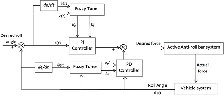
In order to test the feasibility of proposed system in real world application, all discussed controllers were put on test using the HIL experiment setup. Fig. 1 shows the general flowchart of the HIL system for AARB testing.
Fig. 1HIL flowchart
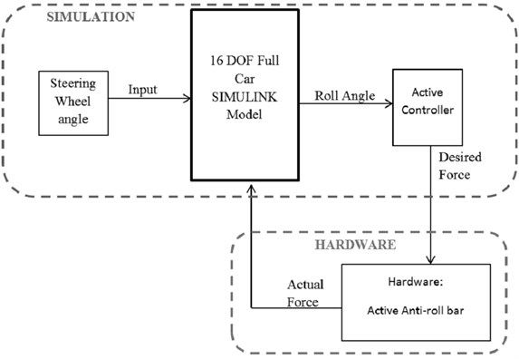
Fig. 2The 16 DOF ride and handling full car model
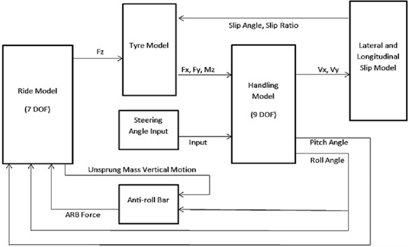
From Fig. 1, it can be seen that vehicle model, input signal and controllers are present in simulation form. The 16 degree of freedom (DOF) full car model is consisted of 7 DOF ride model combined with 9 DOF handling model. This model was adopted from [13, 14]. Muniandy et al. [11] modified this model by adding dedicated ARB model into this 16 DOF full car model. The 7 DOF ride model represents bounce, pitch, roll and four wheels’ vertical motion of the car. The model is based on a number of assumptions, which have been discussed thoroughly in [13]. The equations of the vehicle model, detailed explanation, assumptions and vehicle parameters can be found in Appendix A [13, 14]. Equations related to anti-roll bar were presented in [11]. There are several sub-models, which are ride, Pacejka tire, handling, brake, side slip, and longitudinal slip models are required to represent the 16 DOF full vehicle model. Fig. 4 shows the complete block diagram of the 16 DOF full car model. For HIL experiment, the anti-roll bar block in Fig. 2 is substituted by AARB hardware as shown in Fig. 1.
The actuators used in this experiment are Servomech linear electric actuators which are capable of delivering 1600 N of dynamic force at speed of 240 mm/s, with maximum static load of 10000 N. These actuators were driven by 24 V DC motors with 500 W output power each. Each actuator has 20 cm of stroke, chosen based on maximum ARB travel obtained from AARB simulation results.
The data acquisition system used in this experiment is based on Arduino MEGA 2560 board, where specific code burned to its flash memory so the board acts as a standard data acquisition system. This board receives the desired force signal from the PC via USB cable. The PC is able to run 16 DOF full car SIMULINK model in real time while connected to data acquisition system, allowing real time changes to the connected active system hardware. The desired force signal is then converted into PWM signal and sent to a DC motor driver. The DC motor driver receives power from the power supply (in this case two 12 V car batteries connected in series to provide 24 V DC power supply), and feed the required power to the actuator according to the PWM signal received from the Arduino board. The DC motor driver also receives secondary signal from Arduino, which is the direction signal to determine the stroke direction of the actuator.
Fig. 3HIL signal flow schematics
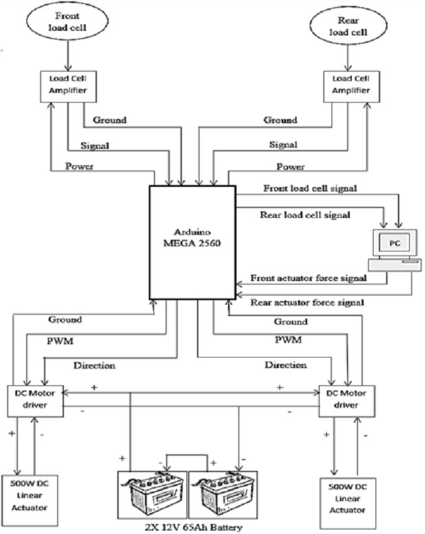
Sensors used for this experiment are tension compression load cells which threaded shafts at both ends. This design was chosen in particular to enable the installation process to be easy. There are only two load cells involved in total, each for front and rear ARB. The sensors are rated at 2000 N for both tension and compression forces. The excitation voltage is 5 V, so there is no need for an external power supply for the sensors. However, in order to amplify the sensors output signal, bi-directional load cell amplifiers were used. Fig. 3 shows the signal flow schematics of all electronics parts involved in this HIL setup.
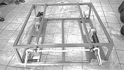
The experiment rig was designed and fabricated exclusively for AARB testing purpose. The HIL prototype for the AARB testing incorporates both front and rear ARB. The ARB used for this setup is 25 mm high performance front anti-roll bar that designed for Mitsubishi Lancer Evolution VII. Both anti-roll bars used in the setup were front anti-roll bars, but one of it assumed to be rear ARB in the simulation model. This is to ensure a balanced design of the rig itself. Furthermore, the real difference between front and rear ARB in a real car (which have fully independent suspension on both front and rear) is just the curves of the bars that were intended to pass through any mechanical components underneath the car. The chosen ARB is also suitable to be installed on the real test car which the simulation model is based on. Fig. 4 shows the finished HIL testing rig.
Fig. 4AARB HIL testing rig
3. Design of controller
This section will be discussing on the controller used to control the operation of AARB HIL testing rig as well as its tuning.
3.1. PI-PD type fuzzy controller
For PI-PD type Fuzzy controller (PI-PD type FLC), the derivative action is placed at the measurement of the process feedback but not after the feedback error [15]. The basic concept of this controller is shown in Fig. 5.
Fig. 5Basic layout of PI-PD controller
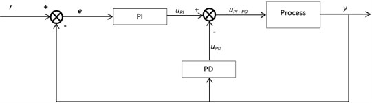
In order to improve the controller’s compatibility to non-linear system, Veeraiah et al. (2004) implemented fuzzy logic to design PI-PD type FLC controller. The controller is designed to preserve the linear structure of conventional PI-PD controller and substitutes the coefficient gains with non-linear fuzzy functions. The output of PI-PD type FLC controller, , is represented by:
where and are the equivalent outputs from Fuzzy PI and Fuzzy PD controllers respectively. By applying bilinear transformation, Fuzzy PI controller output (Muniandy et al., 2015) can be written as:
where is the Fuzzy PI controller output, is the sampling period and is the Fuzzy PI control gain. Similarly, for Fuzzy PD controller, the equation will be:
which is the fuzzy PD controller output and is the fuzzy PD control gain. Both and will be determined by fuzzy rules. This controller’s layout applied in active ARB is shown by the block diagram in Fig. 6.
Fig. 6Block diagram of PI-PD Type Fuzzy Logic controller of AARB system
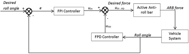
Fig. 7Example of implementation of PI-PD Type Fuzzy Logic controller in Simulink model
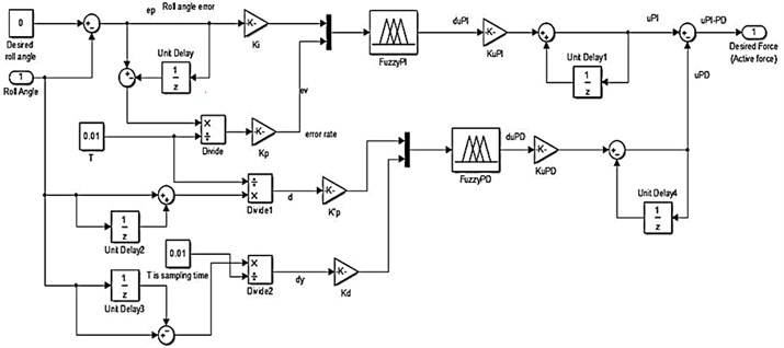
Membership functions and rules will be applied to the fuzzy PI and fuzzy PD controllers can be referred in [11]. The inputs for both controllers will be in terms of roll angle signal. Earlier, it has been stated that fuzzy PI controller has two inputs, which are roll angle error signal, and rate of change of roll angle error signal, . The fuzzy PI controller output, also called as incremental control output is denoted as. The inputs for fuzzy PD controllers are the roll angle, and rate of change of roll angle, . Fig. 7 shows an example of actual construction of PI-PD Type FLC controller in Simulink software with the indication of actual placement for each controller parameter, which are , , , , and . Despite the notations, these parameters act only as input sensitivity ratio in order to avoid undesirable noise in the output. The proportional, derivative and integral actions are expressed in the form of non-linear fuzzy functions.
3.2. Self-tuning fuzzy PID
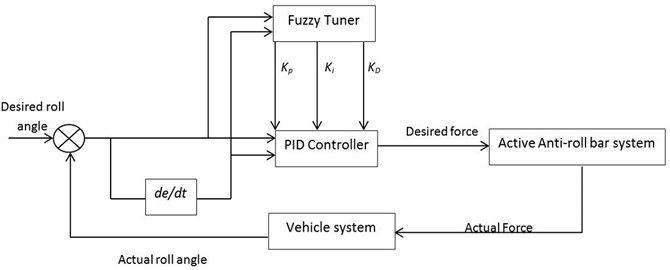
Self-Tuning Fuzzy PID controller was implemented in AARB by Xinpeng and Duan [4] in their attempt to improve the ride and handling of a SUV. The controller algorithm uses conventional approach where the values of PID controller parameters are tuned online by Fuzzy controller depending on the feedback input received from the plant. This approach is more direct compared to the approach used in PI-PD type FLC controller. The general equation for the PID controller is:
where is the body roll error with respect to the desired roll angle which is 0 at all time. The corresponding desired active anti-roll torque is . The body roll angle variety rate is denoted by and the error sum is denoted by. The terms , , and denote integral, proportion and derivatives coefficients respectively. The controller parameters , , and will be self-tuned by fuzzy controller according to the roll angle error, and roll angle error variety rate, The self-tuning ability is well known for its promising results. Fig. 8 shows the general block diagram for the controller.
Fig. 8Controller structure proposed by Xinpeng and Duan (2007)
3.3. Self-tuning fuzzy PI–PD controller
By incorporating classical PI-PD configuration into self-tuning Fuzzy PID method, the STFPI-PD controller is expected to solve derivative kick problem [11]. This controller is designed as an attempt to upgrade the currently available Fuzzy PID controller used in AARB system. The general equation of PI-PD controller will be:
Note that there are 2 proportional actions; and, each for roll angle error, and the direct measurement of roll angle input, repectively. The derivative action is applied at the measurement of roll angle. The performance of AARB system can be adjusted by tuning the parameter , , , and of PI-PD controller to influence the system’s rise time, steady state error, overshoot and settling time. The tuning process of the controller parameters will be done by fuzzy controllers. These fuzzy controllers will receive roll angle error, and error rate, as inputs to tune the value of and; also, the fuzzy controllers that receive roll angle value, and the roll rate value, as inputs will tune the values of and . The fuzzy rules, membership functions and tuning procedures are reported in [11]. Fig. 9 shows the general block diagram of the proposed controller.
Fig. 9General Block diagram of Self-Tuning Fuzzy PI-PD controller
4. Handling dynamics test
This section discusses the simulation tests used to evaluate the performance of the controller and the hardware.
4.1. Slalom test
Slalom test was carried out at 2 different speeds. The test evaluates three major variables to show the performance of the three controllers. These variables are roll angle, roll rate and actuator force. For actuator force however, it is showcased in order to show the different trend on each controllers’ reaction. Having a low magnitude in force output does not mean advantage except low power usage. Fig. 10 shows roll angle response for 40 km/h slalom manoeuvre test.
From Fig. 10, it can be seen that STFPI-PD controller reduces roll angle to negligible state, with one visible spike at 5.5th second. It should be noted that problems regarding HIL setup discussed earlier applies to all tests. STFPID controller manages to reduce roll angle significantly when compared to passive system, but could not bring the roll motion closer to zero like the other two controllers. PI-PD Type FLC follows the trend of STF PID controller for the first three seconds and settles down at almost zero position until the 5th second where the roll angle spikes to a magnitude equal to passive result. This is due to the limitation of the controller that is unable to produce the direction of a desired force efficiently and causes the roll angle to increase abruptly until the controller reacts again. The weakness of PI-PD Type FLC in predicting the desired directions is maybe due to the use of small number of membership functions compared to other two controllers as reported in [11]. The lack of detailed membership functions promotes the controller to make various mistakes when comes to determining acting force direction. This can be seen at force distribution figure later. Fig. 11 shows the roll rate response for this test.
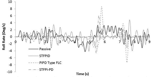
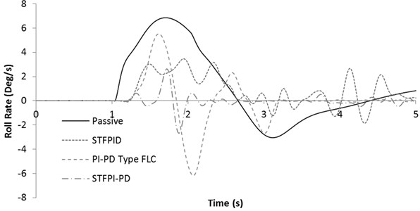
It can be observed that STF PID controller creates more oscillations compared to the other two controllers. This oscillation degrades ride comfort in comparison with passive system. While maintaining the roll rate at almost zero position, STFPI-PD controller only spikes once exceeding passive roll rate value at 5.5th second. This is because the actuator meets the stroke limit and could not extend/retract any further. When this situation appears, the vehicle roll angle starts to rise, following the direction similar to passive system as no additional active force acting to the system. The roll angle continues to rise until the steering wheel changes direction and causing the vehicle to roll in the opposite direction. The controller immediately takes action once the vehicle rolls at opposite direction and resets the roll angle back to zero position.
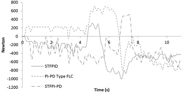
However, this sudden correction action by the controller causes roll rate to increase which is presented in Fig. 11. It is important to take note that this problem will seldom occur in real car application due to several reasons. One of the reasons are, the stroke length of the experimental actuator was determined based on simulation tests alone. The estimation itself may not be a problem, but the capability of the actuator to return back to its zero position is limited in HIL setup due to lack of actual body weight and vehicle main suspension system to return back the vehicle to its default position every time. In HIL setup, only ARB acts as a spring to push/pull back the actuator to its default position. It is crucial to know that a significant amount of force is required to push/pull back the actuator shaft to its default position even when there is no power running through it; although the actuator itself were designed not to self-lock. This is the nature of the high power linear electric actuator which incorporates very strong magnet in the motor. The failure of the actuator shaft to return back to its default position quickly causes the zero position to drift and the actuator reach maximum stroke point pre-maturely. Other than that, STF PI-PD controller manages to improve ride performance by keeping the roll rate at minimum. PI-PD type FLC exceeds the passive roll rate value twice and the magnitude is the largest compared to all tested controllers. Fig. 12 shows the active force response for the mentioned test.
Fig. 10Roll angle response for 40 km/h slalom test
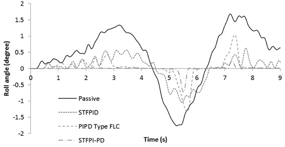
Fig. 11Roll rate response for 40 km/h slalom test
It can be observed that STF PID controller creates more oscillations compared to the other two controllers. This oscillation degrades ride comfort in comparison with passive system. While maintaining the roll rate at almost zero position, STFPI-PD controller only spikes once exceeding passive roll rate value at 5.5th second. This is because the actuator meets the stroke limit and could not extend/retract any further. When this situation appears, the vehicle roll angle starts to rise, following the direction similar to passive system as no additional active force acting to the system. The roll angle continues to rise until the steering wheel changes direction and causing the vehicle to roll in the opposite direction. The controller immediately takes action once the vehicle rolls at opposite direction and resets the roll angle back to zero position. However, this sudden correction action by the controller causes roll rate to increase which is presented in Fig. 11. It is important to take note that this problem will seldom occur in real car application due to several reasons. One of the reasons are, the stroke length of the experimental actuator was determined based on simulation tests alone. The estimation itself may not be a problem, but the capability of the actuator to return back to its zero position is limited in HIL setup due to lack of actual body weight and vehicle main suspension system to return back the vehicle to its default position every time. In HIL setup, only ARB acts as a spring to push/pull back the actuator to its default position. It is crucial to know that a significant amount of force is required to push/pull back the actuator shaft to its default position even when there is no power running through it; although the actuator itself were designed not to self-lock. This is the nature of the high power linear electric actuator which incorporates very strong magnet in the motor. The failure of the actuator shaft to return back to its default position quickly causes the zero position to drift and the actuator reach maximum stroke point pre-maturely. Other than that, STF PI-PD controller manages to improve ride performance by keeping the roll rate at minimum. PI-PD type FLC exceeds the passive roll rate value twice and the magnitude is the largest compared to all tested controllers. Fig. 12 shows the active force response for the mentioned test.
Fig. 12Active force response for 40 km/h slalom test
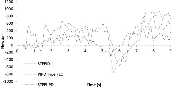
All tested controllers show similar trend in terms of force distribution. PI-PD type FLC controller shows delay in response to change direction in comparison with the other two controllers. STF PID controller generates the lowest force and capable of making a smooth change in direction. However, the oscillations in its force distributions may cause further impact negatively on roll motion even if the force magnitude was increased. This can be seen in Fig. 11, even with less amount of force, the vehicle roll motion keeps on oscillating more than the passive system at the first three seconds. In fact, with higher active force, this oscillation will be worsened; hence the controller limits its response to continue provide lower force magnitude throughout the test. This is one of the features of self-tuning controllers which can act appropriately according to the sensed disturbances. However, STFPI-PD controller shows that its self-tuning capability is much more efficient as it can give higher forces with higher agility to overcome any fluctuations that may be rise from the steering angle input noises. Next, the roll angle response for 50 km/h slalom test is presented in Fig. 13.
Similar results are shown. Earlier discussion is more evident. Figs. 14 and 15 shows roll rate response and active force response for 50 km/h slalom test respectively.
Fig. 13Roll angle response for 50 km/h slalom test
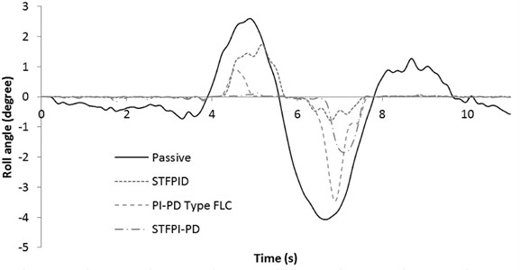
Fig. 14Roll rate response for 50 km/h slalom test
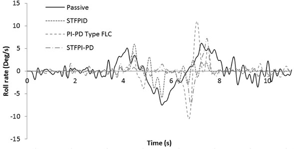
Fig. 15Active force response for 50 km/h slalom test
As can be seen in Fig. 14, PI-PD Type FLC causes significant rise in roll rate at approximately the 7th second, exceeding the magnitude created by passive system. This will definitely impact ride comfort negatively. This may be due to the failure of the controller to provide active force in the negative direction at the 6th second as generated by the other controllers. The trend of STF PI-PD controller sets it apart from other controllers as the controller continues to give negative force until approximately the 6.5th second. At approximately the 7th second, in order to overcome the rising roll angle, the controller gives force at positive direction abruptly but failed to completely reduce the roll angle due to the actuator shafts reaches its limit. The evidence can be seen from 7th to 7.5th seconds where the force value stalls at almost constant as the actuator could not move any further. This kind of constant force values is not visible with the other tested controller outputs, further supporting the claim. The reason of this error can be also caused by quick change of the force direction with higher magnitude, which makes the actuator impossible to return to the default position in a very short time. The use of dampening element might be useful to overcome this problem, where in a real vehicle, the vehicle’s main dampers will assist to lessen this negative effect.
Following are the tables presenting the improvement made by the proposed controllers in comparison with the passive system. Tables 1 and 2 show the RMS value of the presented variables for 40 and 50 km/h slalom test respectively.
Table 1Percentage of improvement in 40 km/h slalom test
RMS | Roll Angle (Degree) | Roll Rate (Degree/s) | ARB Force (Newton) | |
Passive | RMS | 0.9709 | 1.4990 | – |
STF PID | RMS | 0.3798 | 1.5163 | 202.23 |
Improvement (%) | 60.88 | –1.15 | – | |
PI-PD Type FLC | RMS | 0.3149 | 1.6513 | 447.18 |
Improvement (%) | 67.57 | –10.16 | – | |
STF PI-PD | RMS | 0.0981 | 0.08846 | 454.84 |
Improvement (%) | 89.89 | 40.98 | – | |
Table 2Percentage of improvement in 50 km/h slalom test
RMS | Roll Angle (Degree) | Roll Rate (Degree/s) | ARB Force (Newton) | |
Passive | RMS | 1.5395 | 2.5550 | – |
STF PID | RMS | 0.4592 | 1.2511 | 457.44 |
Improvement (%) | 70.17 | 51.03 | – | |
PI-PD Type FLC | RMS | 0.6366 | 2.2703 | 452.04 |
Improvement (%) | 58.65 | 11.14 | – | |
STF PI-PD | RMS | 0.3879 | 1.3883 | 422.38 |
Improvement (%) | 74.80 | 45.66 | – | |
It is found that STFPI-PD controller improves both its roll angle and roll rate response in comparison with passive system. This result may be improved further if the STFPI-PD controller does not suffer from actuator stroke limitation. Table 1 shows both STFPID and PI-PD Type FLC degrade ride comfort by increasing roll rate of the vehicle. However, at higher speed, all controllers manage to improve roll rate response in comparison with passive. PI-PD type FLC worsens the roll rate response up to –10.16 % for 40 km/h slalom test due to obvious spikes at roll rate magnitude, as can be seen in Fig. 11. STFPI-PD controller remains as the best among the tested controllers.
4.2. Step steer test
In order to evaluate steady state performance, step steer test has been carried out at 60 km/h speed by using steering input signal similar to that used in [4]. Similar input were chosen because the result will better reflect the actual difference between simulation output (as discussed by Xinpeng and Duan [4]) and the experimental output obtained in this research. Furthermore, to evaluate steady state performance, it is required to have noise free input to allow the system output settles to a constant value within the margin of error. For this test, the steering wheel is turned suddenly to the left 90° and keeping the steering wheel position fixed until the end of the test. The steering wheel takes about one second to turn from 0° to 90° left. The vehicle moves at a constant speed of 60 km/h throughout the test. Fig. 16 shows the roll angle response for this test.
The STF PID controller continues to fluctuate for 5 seconds, where the other two tested controller settles down within the given period. Overshoot cannot be avoided due to the actual hardware inertia. However, for STF PI-PD controller small overshoot occurs, reaching not higher than 0.5°, which will not be felt by most of the passengers. STF PI-PD controller also has quick settling time, which is within 1 second after the input given. The overshoot for PI-PD type FLC is more evident, reaching approximately 2°, however manage to settle down near zero position within the margin of error similar to STF PI-PD controller. PI-PD type FLC takes approximately 2 seconds to settle down. The steady state error for both PI-PD Type FLC and STF PI-PD controller is too small for a passenger to feel in real driving environment. Next, Fig. 17 shows the roll rate response for the step steer test.
Fig. 16Roll angle response for 60 km/h step steer test
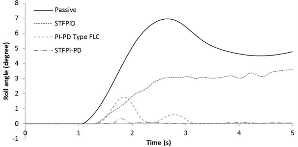
Fig. 17Roll rate response for 60 km/h step steer test
It is expected that STF PID controller will continue to fluctuate and increases the roll rate with time. As mentioned earlier, STF PID controller is not suitable for a system with high noise. For this test, the noise is from the sensors since there is no noise from the steering angle input itself. Once the model given constant input for considerable amount of time, the sensor’s signal drift causes the controller lose control and starts to fluctuates, as can be seen after the 3.5th seconds. A typical load cell will has its signal to drift if it is given constant load for longer period of time. This is due to the nature of quartz crystal in the sensor itself. However, both PI-PD Type FLC and STF PI-PD controller manages to overcome this problem and settles down to almost zero position within 5 seconds frame. STF PI-PD performs the best in improving ride comfort in this test. PI-PD type FLC clocks highest roll rate magnitude due to its overshoot characteristics. Again, this is affected by the limited sensitivity of the controller due to small number of Fuzzy membership functions. Fig. 18 shows the force response for the mentioned test.
Fig. 18 shows that STF PI-PD controller requires the largest amount of force in order to reduce steady state error. It can be seen that all controllers seem to have their output force reducing with time. This is because the whole HIL setup is running on battery power. A battery could not provide high ampere output (higher than the value intended by the manufacturer) in a constant manner for a long period. Due to internal chemical reaction, high ampere output will cause the battery to drop voltage, hence reducing its output power. This is the reason why that step steer test was not carried out at higher speed, as more power is required and the battery will lose its power before the controller can achieve steady state. Other than that, test speed is limited to avoid possible risk of damage on other mechanical parts in the HIL setup. Furthermore, the reason of fluctuations of roll rate by the output of STF PID controller is not caused by limited power supply by the battery, because Fig. 18 clearly shows that STF PID controller uses the least amount of energy compared to STF PI-PD. STF PI-PD controller on the other hand, uses significantly higher force, up to 1600 N in order to suppress roll angle while drawing the energy from the same power supply as STF PID controller did. Table 3 shows the percentage of improvement made by the presented controllers in step steer test.
Fig. 18Active force response for 60 km/h step steer test
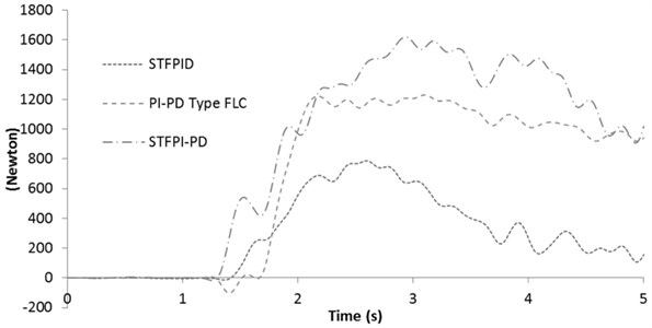
Table 3Percentage of improvement in 60 km/h step steer test
RMS | Roll Angle (Degree) | Roll Rate (Degree/s) | ARB Force (Newton) | |
Passive | RMS | 4.4365 | 2.8941 | – |
STF PID | RMS | 2.4073 | 1.3974 | 395.87 |
Improvement (%) | 45.73 | 51.71 | – | |
PI-PD Type FLC | RMS | 0.4985 | 1.8456 | 866.05 |
Improvement (%) | 88.76 | 36.23 | – | |
STF PI-PD | RMS | 0.0730 | 0.5360 | 1070.76 |
Improvement (%) | 98.35 | 81.47 | – | |
Again, STF PI-PD controller performs well in this test and reduce roll angle up to 98.35 % in comparison with passive system. The roll rate is also improved up to 81.47 %, hence ride comfort is significantly improved in steady state condition. PI-PD type FLC is also able to improve roll angle and roll rate response in comparison with passive system. However, if compared with STF PID controller, PI-PD Type FLC seems to perform lower in terms of roll rate reduction. These results shows that the proposed controller, STF PI-PD has a smoother response in the steady state region, with minor overshoot and fluctuations in the transient region. The steady state error is also negligible for both PI-PD Type FLC and STF PI-PD controllers.
4.3. Stability analysis
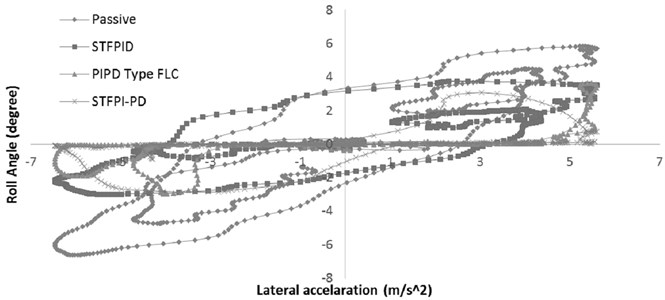
Fig. 19 shows the change of body roll angle in response to lateral acceleration. The effective lateral acceleration at the vehicle CG throughout the tests are from approximately –6 to 6 m/s2 (–0.61 to 0.61G), as can be seen in Fig. 19. The lateral acceleration acting on the passive vehicle body is equal to the vehicle fitted with active system. According to [4], when the vehicle experience high lateral acceleration (at 0.6G) while having large roll angle, the vehicle will loss control. From Fig. 19, it can be seen that the vehicle fitted with STFPI-PD control system will retain its control due to roll angle value closer to zero. In fact, the STFPI-PD controller is able to retain negligible roll angle throughout the entire range of tested lateral acceleration. STFPID does improve roll angle compared to passive system, but the magnitude is still noticeable at 4° on 5.8 m/s2. PI-PD type FLC fails to retain the vehicle stability at higher than 4.5 m/s2 lateral acceleration value and produces high roll angle similar to STFPID controller. It can be said that the controller’s optimum working range is limited and tend to be out of control when high amount of lateral acceleration being applied. This is a dangerous since the driver will experience sudden roll change without prior warning until the vehicle is about to lose control. In contrast to that, STFPI-PD controller is able to hold the roll angle closer to zero at any given lateral acceleration value and ensures driver safety. The minor error caused by STFPI-PD is related to stroke length limitation as discussed earlier, as the data plots are mostly focused about zero point.
Fig. 19Relation between lateral acceleration and vehicle roll angle
The effective lateral acceleration at the vehicle CG throughout the tests are from approximately –6 to 6 m/s2 (–0.61 to 0.61G), as can be seen in Fig. 19. The lateral acceleration acting on the passive vehicle body is equal to the vehicle fitted with active system. According to [4], when the vehicle experience high lateral acceleration (at 0.6G) while having large roll angle, the vehicle will loss control. From Fig. 19, it can be seen that the vehicle fitted with STFPI-PD control system will retain its control due to roll angle value closer to zero. In fact, the STFPI-PD controller is able to retain negligible roll angle throughout the entire range of tested lateral acceleration. STFPID does improve roll angle compared to passive system, but the magnitude is still noticeable at 4° on 5.8 m/s2. PI-PD type FLC fails to retain the vehicle stability at higher than 4.5 m/s2 lateral acceleration value and produces high roll angle similar to STFPID controller. It can be said that the controller’s optimum working range is limited and tend to be out of control when high amount of lateral acceleration being applied. This is a dangerous since the driver will experience sudden roll change without prior warning until the vehicle is about to lose control. In contrast to that, STFPI-PD controller is able to hold the roll angle closer to zero at any given lateral acceleration value and ensures driver safety. The minor error caused by STFPI-PD is related to stroke length limitation as discussed earlier, as the data plots are mostly focused about zero point.
5. Conclusions
The proposed, STF PI-PD controller, was tested using HIL experiment and compared with STF PID and PI-PD Type FLC controllers’ performance. The objective has been achieved since STF PI-PD controller is successfully implemented using HIL test bench; and significantly reduces the vehicle’s roll motion in tests with vehicle speed of 40, 50 and 60 km/h. The presented HIL test bench is able to simulate the dynamics of both front and rear AARB system simultaneously, hence the practicality of implementing double AARB system in a real car is observed. STF PID, a controller that previously studied in AARB system, is also successfully tested using an experimental setup. STF PI-PD controller performs the best among the tested controllers. STF PI-PD controller is able to reduce 87.68 % of roll angle in average, in comparison with passive system. In terms of roll rate, STF PI-PD performs 16.18 % better than STF PID in average and 50.04 % better than passive counterpart; despites its mechanical flaws. The controller which is adapted from robotic industry, PI-PD Type FLC is also able to outperform STF PID controller in terms of roll angle reduction where it improved 71.66 % in average compared to passive system. However, roll rate response shown no impressive results by PI-PD type FLC where only 12.46 % improvement compared to passive system. PI-PD Type FLC does not significantly contribute to ride comfort. STF PID controller reduces 58.93 % of roll angle and 33.86 % of roll rate in average compared to passive system. Given that STF PID was originally designed for AARB system, where else PI-PD Type FLC was not, it is expected to see STF PID controller have better balance in improving both ride and handling compared to PI-PD Type FLC.
STF PI-PD controller outperforms the performance of STF PID controller because of its algorithm which is more suitable for environment with high noises, hence becoming a better controller for the use in AARB system. Derivative kick problem may not be visible clearly in the experimental result, but the STFPID controller does suffers in massive drop on performance when compared to its simulation results. Being a controller with self-tune capability, the Fuzzy rules restricts from using higher force whenever fluctuations in variables were detected in order to achieve better control. This limits the full potential of STF PID controller, hence is not suitable for high noise environment. However, STF PI-PD controller, also a self-tune controller is able to cope with the system and use the full capability of the hardware in order to reduce roll motion closer to zero due to absence of kick problem from the derivative parameter. STF PI-PD controller is also capable of maintaining the vehicle body at almost zero roll angle throughout a wide range of lateral acceleration, which ensures balance grip at all four wheels while taking corners. It can be concluded that STF PI-PD controller can be used in AARB system to improve a passenger car’s ride comfort and handling. PI-PD Type FLC controller on the other hand, is being less sensitive against the direction of the acting forces, causing abrupt increase in roll rate when tested by using HIL setup.
Several problems were faced during the AARB HIL experiment, such as the actuator reaching its maximum stroke point in the middle of the test run. This is due to rapid changes of force value makes the actuator shaft drifted away from zero position, and end up at the end position of the stroke. This problem can be overcome in a real car because the body weight and the main suspension of the car will push back the actuator to default position effectively. In HIL setup, the power capacity of the tested ARB is not enough to push back the actuator to default position at high speed, considering the amount of force needed in order to move the actuator shaft without power. For future studies, it is recommended to use stiffer ARB, which will greatly reduce the travelling distance of the actuator; and by using an actuator with longer stroke length. Other than that, the actuator itself have limited capabilities in changing direction rapidly since the motor drives the shaft via belt, where this belt often slips when the motor changes directions at a fast pace. A custom built electric linear actuator is better if the system is planned for commercial use. Further recommendations are to use a proper DC power supply for the actuators instead of battery; and carry out ride testing such as bump hits for detailed ride comfort analysis.
References
-
Kim H. J., Park Y. P. Investigation of robust roll motion control considering varying speed and actuator dynamics. Mechatronics, Vol. 14, 2004, p. 35-54.
-
Cimba D., Wagner J., Baviskar A. Investigation of active torsion bar actuator configurations to reduce vehicle body roll. Vehicle System Dynamics: International Journal of Vehicle Mechanics and Mobility, Vol. 44, Issue 9, 2006, p. 719-736.
-
Cronje P. H., Els P. S. Improving off-road vehicle handling using an active anti-roll bar. Journal of Terramechanics, Vol. 47, 2010, p. 179-189.
-
Xinpeng T., Duan X. Simulation and study of active roll control for SUV based on fuzzy PID. SAE Technical Paper 2007-01-3570, 2007.
-
Yim S., Yi K. Design of active roll control system and integrated chassis control for hybrid 4WD vehicle. The 14th International IEEE Conference on Intelligent Transportation Systems, Washington DC, 2011.
-
Sampson D. J. M., Cebon D. Active roll control of single unit heavy road vehicles. Vehicle System Dynamics: International Journal of Vehicle Mechanics and Mobility, Vol. 40, Issue 4, 2003, p. 229-270.
-
Stone E. J., Cebon D. Control of semi-active anti-roll systems on heavy vehicles. Vehicle System Dynamics: International Journal of Vehicle Mechanics and Mobility, Vol. 48, Issue 10, 2010, p. 1215-1243.
-
Cech I. Anti-roll and active roll suspensions. Vehicle System Dynamics: International Journal of Vehicle Mechanics and Mobility, Vol. 33, Issue 2, 2000, p. 91-106.
-
Sorniotti A., Velardocchia M., Danesin D., Krief P. Active roll control to increase handling and comfort. SAE Technical Paper 2003-01-0962, 2003.
-
Mizuta Y., Suzumura M., Matsumoto S. Ride comfort enhancement and energy efficiency using electric active stabilizer system. Vehicle System Dynamics: International Journal of Vehicle Mechanics and Mobility, Vol. 48, Issue 11, 2010, p. 1305-1323.
-
Muniandy V., Samin P., Jamaluddin H. Application of self-tuning fuzzy PI-PD controller in active anti-roll bar system for passenger car. Vehicle System Dynamics: International Journal of Vehicle Mechanics and Mobility, http://dx.doi.org/10.1080/00423114.2015.1073336, 2015.
-
Sorniotti A., Morgando A., Velardocchia M. Active roll control: system design and hardware-in-the-loop test bench. Vehicle System Dynamics: International Journal of Vehicle Mechanics and Mobility, Vol. 44, Issue 1, 2006, p. 489-505.
-
Samin P. Hybrid stability augmentation system-force control of semi-active suspension with magnetorheological damper. Ph.D. Thesis, Universiti Teknologi Malaysia, Malaysia, 2010.
-
Abu Bakar S. A., Masuda R., Hashimoto H., Inaba T., Jamaluddin H., Samin P. Active suspension system in improving ride and handling performance of electric vehicle conversion. International Journal of Electric and Hybrid Vehicles, Vol. 4, 2012, p. 24-53.
-
Veeraiah M. P., Majhi S., Mahanta C. Fuzzy proportional integral – proportional derivative (PI-PD) controller. Proceeding of the American Control Conference, Boston, Massachusetts, 2004.
Cited by
About this article

The authors wish to thank the Ministry of Higher Education (MOHE) and the Universiti Teknologi Malaysia (UTM) for providing the research facilities and support, especially all staff’s of Faculty of Mechanical Engineering, Universiti Teknologi Malaysia. This research is supported using a research grant, Vote No. Q.J130000.2524.09H92 and R.J130000.7824.4F94.
Vijayapragas a/l Muniandy designed, fabricate and run the experiment to obtain the results; designed the controller as well. Pakharuddin bin Mohd Samin is a main supervisor for this study; guided through all decision making and model analysis. The mathematical model is based on his model, which further enhanced/improved. Hishamuddin Jamaluddin is the co-supervisor; proof read the whole manuscript and make sure all the contents are on par. Roslan Abdul Rahman is the second co-supervisor. He is in charge on allocating budget for purchasing of experiment equipment and also providing lab space for the experiment rig. Saiful Abu Bakar is a lecturer who assisted in formatting, proof reading and producing high quality images and figures for the use in the manuscript.
